| ID | Description | Links | Other Attributes | Discussion | Errors | Type | Contact | Imports | Reference | Syntax | Additional Req't | ||||||||||||||||||||||||||||||||||||||||||||||||||||||||||||||||||||||||||||||||||||||||||||||||||||||||||||||||||||||||||||||||||
|---|---|---|---|---|---|---|---|---|---|---|---|---|---|---|---|---|---|---|---|---|---|---|---|---|---|---|---|---|---|---|---|---|---|---|---|---|---|---|---|---|---|---|---|---|---|---|---|---|---|---|---|---|---|---|---|---|---|---|---|---|---|---|---|---|---|---|---|---|---|---|---|---|---|---|---|---|---|---|---|---|---|---|---|---|---|---|---|---|---|---|---|---|---|---|---|---|---|---|---|---|---|---|---|---|---|---|---|---|---|---|---|---|---|---|---|---|---|---|---|---|---|---|---|---|---|---|---|---|---|---|---|---|---|---|---|---|---|---|---|---|---|
| NTCIP_1201-1 |
1 General |
◾ Part:
Main1
◾ Type:
Text
|
Text | ||||||||||||||||||||||||||||||||||||||||||||||||||||||||||||||||||||||||||||||||||||||||||||||||||||||||||||||||||||||||||||||||||||||||||
| NTCIP_1201-2 |
1.1 Scope |
◾ Part:
Main1
◾ Type:
Text
|
Text | ||||||||||||||||||||||||||||||||||||||||||||||||||||||||||||||||||||||||||||||||||||||||||||||||||||||||||||||||||||||||||||||||||||||||||
| NTCIP_1201-3 |
The NTCIP 1200 series defines standardized data elements that can be exchanged between a traffic management center (or any other management station) and a field device. This document identifies and defines data elements that can be supported by multiple types of devices (e.g., actuated signal controllers, dynamic message signs, connected vehicle roadside units). All data elements defined in this document have been deprecated. Current data elements to fulfill a similar set of user needs can be found in ISO 26048-1. The data defined in this standard was originally defined using the Structure of Management Information Version 1 (SMIv1) format, as defined in RFC 1212, and intended for implementations using the Simple Network Management Protocol Version 1 (SNMPv1). This document migrates the original data element definitions to use SMIv2, as defined by RFC 2578, to enable its unambiguous exchange when using SNMPv3. This document does not apply to interfaces using SNMPv1 and the continued use of SNMPv1 is discouraged. New implementations should use data elements defined in ISO 26048-1. This document is intended to allow the data originally developed for SNMPv1 devices to be exchanged via an SNMPv3 interface. Specifically, this document is envisioned to address the interface between a management station and a proxy agent as shown in Figure 1. |
◾ Part:
Main1
◾ Type:
Text
|
Text | ||||||||||||||||||||||||||||||||||||||||||||||||||||||||||||||||||||||||||||||||||||||||||||||||||||||||||||||||||||||||||||||||||||||||||
| NTCIP_1201-2161 |
Focus of this standard |
◾ Part:
Main1
◾ Type:
Figure
|
Figure | ||||||||||||||||||||||||||||||||||||||||||||||||||||||||||||||||||||||||||||||||||||||||||||||||||||||||||||||||||||||||||||||||||||||||||
| NTCIP_1201-2171 |
Figure 1 reflects the expectation that management stations will be upgraded to SNMPv3 before field devices due to their limited numbers, but the data defined in this document applies for any SNMPv3 interface using the previously defined data included in this document, even those where the field device is upgraded first. |
◾ Part:
Main1
◾ Type:
Note
|
Note | ||||||||||||||||||||||||||||||||||||||||||||||||||||||||||||||||||||||||||||||||||||||||||||||||||||||||||||||||||||||||||||||||||||||||||
| NTCIP_1201-2158 |
The management station is typically a traffic management center but could be any device acting as a SNMPv3 command generator (e.g., a field technician's laptop, a connected vehicle roadside unit). The field device is the device that is to be controlled and/or monitored by the management station. The proxy agent is responsible for providing secure communications between the traffic management center to a location very near the field device where a level of physical security can be provided. The interface between the proxy agent and the field device is not addressed by this standard; however, the expectation is that this interface is likely either: |
◾ Part:
Main1
◾ Type:
Text
|
Text | ||||||||||||||||||||||||||||||||||||||||||||||||||||||||||||||||||||||||||||||||||||||||||||||||||||||||||||||||||||||||||||||||||||||||||
| NTCIP_1201-2159 |
an SNMPv1 interface (when the proxy agent is a separate physical device) or |
◾ Part:
Main1
◾ Type:
List Level 1
|
List Level 1 | ||||||||||||||||||||||||||||||||||||||||||||||||||||||||||||||||||||||||||||||||||||||||||||||||||||||||||||||||||||||||||||||||||||||||||
| NTCIP_1201-2160 |
an application programming interface (when the proxy agent is implemented as a software routine within the field device). |
◾ Part:
Main1
◾ Type:
List Level 1
|
List Level 1 | ||||||||||||||||||||||||||||||||||||||||||||||||||||||||||||||||||||||||||||||||||||||||||||||||||||||||||||||||||||||||||||||||||||||||||
| NTCIP_1201-366 |
The manager communicates to the proxy agent using legacy versions of NTCIP data (as defined by this document) contained in SNMPv3 requests. If the request contains valid security credentials for the requested data, the proxy agent translates the SNMPv3 request into a format understood by the field device (e.g., SNMPv1) and forwards it to the older field device. The field device responds to the request and the proxy agent translates this response into SNMPv3. The proxy agent could be internal or external to the field device. |
◾ Part:
Main1
◾ Type:
Text
|
Text | ||||||||||||||||||||||||||||||||||||||||||||||||||||||||||||||||||||||||||||||||||||||||||||||||||||||||||||||||||||||||||||||||||||||||||
| NTCIP_1201-2162 |
Throughout the remainder of this document, the term "data element" is replaced with the term "object type" to align with SNMPv3 terminology. |
◾ Part:
Main1
◾ Type:
Note
|
Note | ||||||||||||||||||||||||||||||||||||||||||||||||||||||||||||||||||||||||||||||||||||||||||||||||||||||||||||||||||||||||||||||||||||||||||
| NTCIP_1201-4 |
1.2 References |
◾ Part:
Main1
◾ Type:
Text
|
Text | ||||||||||||||||||||||||||||||||||||||||||||||||||||||||||||||||||||||||||||||||||||||||||||||||||||||||||||||||||||||||||||||||||||||||||
| NTCIP_1201-5 |
The following documents are referenced by this document. At the time of publication, the editions indicated were valid. |
◾ Type:
Text
|
Text | ||||||||||||||||||||||||||||||||||||||||||||||||||||||||||||||||||||||||||||||||||||||||||||||||||||||||||||||||||||||||||||||||||||||||||
| NTCIP_1201-6 |
1.2.1 Normative References |
◾ Type:
Text
|
Text | ||||||||||||||||||||||||||||||||||||||||||||||||||||||||||||||||||||||||||||||||||||||||||||||||||||||||||||||||||||||||||||||||||||||||||
| NTCIP_1201-7 |
Normative references contain provisions that, through reference in this text, constitute provisions of this document. All standards are subject to revision, and parties to agreements based on this standard are encouraged to investigate the possibility of applying the most recent editions of the standard listed. |
◾ Type:
Text
|
Text | ||||||||||||||||||||||||||||||||||||||||||||||||||||||||||||||||||||||||||||||||||||||||||||||||||||||||||||||||||||||||||||||||||||||||||
| NTCIP_1201-8 |
1.2.1.1 AASHTO / ITE / NEMA NTCIP 8004 v03Structure and Identification of Management Information (SMI) published (Pending) |
◾ Type:
Reference
|
Reference | ||||||||||||||||||||||||||||||||||||||||||||||||||||||||||||||||||||||||||||||||||||||||||||||||||||||||||||||||||||||||||||||||||||||||||
| NTCIP_1201-13 |
1.2.1.2 IETF RFC 2021Remote Network Monitoring Management Information Base Version 2 using SMIv2, January 1997 |
◾ Type:
Reference
|
Reference | ||||||||||||||||||||||||||||||||||||||||||||||||||||||||||||||||||||||||||||||||||||||||||||||||||||||||||||||||||||||||||||||||||||||||||
| NTCIP_1201-15 |
1.2.1.3 IETF RFC 2578Structure of Management Information Version 2 (SMIv2), April 1999 |
◾ Type:
Reference
|
Reference | ||||||||||||||||||||||||||||||||||||||||||||||||||||||||||||||||||||||||||||||||||||||||||||||||||||||||||||||||||||||||||||||||||||||||||
| NTCIP_1201-17 |
1.2.1.4 IETF RFC 2579Textual Conventions for SMIv2, April 1999 |
◾ Type:
Reference
|
Reference | ||||||||||||||||||||||||||||||||||||||||||||||||||||||||||||||||||||||||||||||||||||||||||||||||||||||||||||||||||||||||||||||||||||||||||
| NTCIP_1201-19 |
1.2.1.5 IETF RFC 2580Conformance Statements for SMIv2, April 1999 |
◾ Type:
Reference
|
Reference | ||||||||||||||||||||||||||||||||||||||||||||||||||||||||||||||||||||||||||||||||||||||||||||||||||||||||||||||||||||||||||||||||||||||||||
| NTCIP_1201-3280 |
1.2.1.6 IETF RFC 3418Management Information Base (MIB) for the Simple Network Management Protocol (SNMP), December 2002 |
◾ Type:
Reference
|
Reference | ||||||||||||||||||||||||||||||||||||||||||||||||||||||||||||||||||||||||||||||||||||||||||||||||||||||||||||||||||||||||||||||||||||||||||
| NTCIP_1201-25 |
1.2.1.7 ISO/IEC/IEEE 24765:2017Systems and software engineering – Vocabulary |
◾ Type:
Reference
|
Reference | ||||||||||||||||||||||||||||||||||||||||||||||||||||||||||||||||||||||||||||||||||||||||||||||||||||||||||||||||||||||||||||||||||||||||||
| NTCIP_1201-27 |
1.2.1.8 ISO 26048-1Intelligent transport systems – Field device SNMP data interface – Part 1: Global objects |
◾ Type:
Reference
|
Reference | ||||||||||||||||||||||||||||||||||||||||||||||||||||||||||||||||||||||||||||||||||||||||||||||||||||||||||||||||||||||||||||||||||||||||||
| NTCIP_1201-28 |
1.2.2 Other References |
◾ Type:
Text
|
Text | ||||||||||||||||||||||||||||||||||||||||||||||||||||||||||||||||||||||||||||||||||||||||||||||||||||||||||||||||||||||||||||||||||||||||||
| NTCIP_1201-29 |
Other references are included to provide a more complete understanding of this document and its relationship to other documents. |
◾ Type:
Text
|
Text | ||||||||||||||||||||||||||||||||||||||||||||||||||||||||||||||||||||||||||||||||||||||||||||||||||||||||||||||||||||||||||||||||||||||||||
| NTCIP_1201-3281 |
1.2.2.1 AASHTO / ITE / NEMA NTCIP 2301 v02Simple Transportation Management Framework Application Profile (Pending) |
◾ Type:
Reference
|
Reference | ||||||||||||||||||||||||||||||||||||||||||||||||||||||||||||||||||||||||||||||||||||||||||||||||||||||||||||||||||||||||||||||||||||||||||
| NTCIP_1201-32 |
1.2.2.2 AASHTO / ITE / NEMA NTCIP 8005 v02Procedures for Creating Management Information Base (MIB) Files published (Pending) |
◾ Type:
Reference
|
Reference | ||||||||||||||||||||||||||||||||||||||||||||||||||||||||||||||||||||||||||||||||||||||||||||||||||||||||||||||||||||||||||||||||||||||||||
| NTCIP_1201-35 |
1.2.2.3 IETF RFC 854Telnet Protocol Specification |
◾ Type:
Reference
|
Reference | ||||||||||||||||||||||||||||||||||||||||||||||||||||||||||||||||||||||||||||||||||||||||||||||||||||||||||||||||||||||||||||||||||||||||||
| NTCIP_1201-21 |
1.2.2.4 IETF RFC 3411An Architecture for Describing Simple Network Management Protocol (SNMP) Management Framework, December 2002 |
◾ Type:
Reference
|
Reference | ||||||||||||||||||||||||||||||||||||||||||||||||||||||||||||||||||||||||||||||||||||||||||||||||||||||||||||||||||||||||||||||||||||||||||
| NTCIP_1201-37 |
1.2.2.5 IETF RFC 3412Message Processing and Dispatching for the Simple Network Management Protocol (SNMP), December 2002 |
◾ Type:
Reference
|
Reference | ||||||||||||||||||||||||||||||||||||||||||||||||||||||||||||||||||||||||||||||||||||||||||||||||||||||||||||||||||||||||||||||||||||||||||
| NTCIP_1201-39 |
1.2.2.6 IETF RFC 3413Simple Network Management Protocol (SNMP) Applications, December 2002 |
◾ Type:
Reference
|
Reference | ||||||||||||||||||||||||||||||||||||||||||||||||||||||||||||||||||||||||||||||||||||||||||||||||||||||||||||||||||||||||||||||||||||||||||
| NTCIP_1201-41 |
1.2.2.7 IETF RFC 3415View-based Access Control Model (VACM) for the Simple Network Management Protocol (SNMP), December 2002 |
◾ Type:
Reference
|
Reference | ||||||||||||||||||||||||||||||||||||||||||||||||||||||||||||||||||||||||||||||||||||||||||||||||||||||||||||||||||||||||||||||||||||||||||
| NTCIP_1201-23 |
1.2.2.8 IETF RFC 3416Version 2 of the Protocol Operations for the Simple Network Management Protocol (SNMP) , December 2002 |
◾ Type:
Reference
|
Reference | ||||||||||||||||||||||||||||||||||||||||||||||||||||||||||||||||||||||||||||||||||||||||||||||||||||||||||||||||||||||||||||||||||||||||||
| NTCIP_1201-3282 |
1.2.2.9 IETF RFC 3417Transport Mappings for the Simple Network Management Protocol (SNMP) |
◾ Type:
Reference
|
Reference | ||||||||||||||||||||||||||||||||||||||||||||||||||||||||||||||||||||||||||||||||||||||||||||||||||||||||||||||||||||||||||||||||||||||||||
| NTCIP_1201-43 |
1.2.2.10 IETF RFC 3418Management Information Base (MIB) for the Simple Network Management Protocol (SNMP), December 2002 |
◾ Type:
Reference
|
Reference | ||||||||||||||||||||||||||||||||||||||||||||||||||||||||||||||||||||||||||||||||||||||||||||||||||||||||||||||||||||||||||||||||||||||||||
| NTCIP_1201-45 |
1.2.2.11 IETF RFC 4181Guidelines for Authors and Reviewers of MIB Documents, September 2005 |
◾ Type:
Reference
|
Reference | ||||||||||||||||||||||||||||||||||||||||||||||||||||||||||||||||||||||||||||||||||||||||||||||||||||||||||||||||||||||||||||||||||||||||||
| NTCIP_1201-47 |
1.2.2.12 IETF RFC 5591Transport Security Model for the Simple Network Management Protocol (SNMP), June 2009 |
◾ Type:
Reference
|
Reference | ||||||||||||||||||||||||||||||||||||||||||||||||||||||||||||||||||||||||||||||||||||||||||||||||||||||||||||||||||||||||||||||||||||||||||
| NTCIP_1201-49 |
1.2.2.13 IETF RFC 6353Transport Layer Security (TLS) Transport Model for the Simple Network Management Protocol (SNMP), July 2011 To Be Updated |
◾ Type:
Reference
|
Reference | ||||||||||||||||||||||||||||||||||||||||||||||||||||||||||||||||||||||||||||||||||||||||||||||||||||||||||||||||||||||||||||||||||||||||||
| NTCIP_1201-51 |
1.2.2.14 IETF RFC 6933Entity MIB (Version 4), May 2013 |
◾ Type:
Reference
|
Reference | ||||||||||||||||||||||||||||||||||||||||||||||||||||||||||||||||||||||||||||||||||||||||||||||||||||||||||||||||||||||||||||||||||||||||||
| NTCIP_1201-53 |
1.2.2.15 ISO 15784-2:TBDIntelligent transport systems — Data exchange involving roadside equipment communication — Part 2: Centre to field device communications using SNMP |
◾ Type:
Reference
|
Reference | ||||||||||||||||||||||||||||||||||||||||||||||||||||||||||||||||||||||||||||||||||||||||||||||||||||||||||||||||||||||||||||||||||||||||||
| NTCIP_1201-55 |
1.2.2.16 ISO 21217:2020Intelligent transport systems — Station and communications architecture |
◾ Type:
Reference
|
Reference | ||||||||||||||||||||||||||||||||||||||||||||||||||||||||||||||||||||||||||||||||||||||||||||||||||||||||||||||||||||||||||||||||||||||||||
| NTCIP_1201-57 |
1.2.2.17 ISO 26048-1Intelligent transport systems — Roadside equipment SNMP data interface — Part 3: Triggers |
◾ Type:
Reference
|
Reference | ||||||||||||||||||||||||||||||||||||||||||||||||||||||||||||||||||||||||||||||||||||||||||||||||||||||||||||||||||||||||||||||||||||||||||
| NTCIP_1201-59 |
1.2.2.18 ISO 26048-1Intelligent transport systems — Roadside equipment SNMP data interface — Part 4: Notifications |
◾ Type:
Reference
|
Reference | ||||||||||||||||||||||||||||||||||||||||||||||||||||||||||||||||||||||||||||||||||||||||||||||||||||||||||||||||||||||||||||||||||||||||||
| NTCIP_1201-61 |
1.2.2.19 ISO 26048-1Intelligent transport systems — Roadside equipment SNMP data interface — Part 5: Logs |
◾ Type:
Reference
|
Reference | ||||||||||||||||||||||||||||||||||||||||||||||||||||||||||||||||||||||||||||||||||||||||||||||||||||||||||||||||||||||||||||||||||||||||||
| NTCIP_1201-63 |
Intelligent transport systems — Roadside equipment SNMP data interface — Part 6: Commands |
◾ Type:
Reference
|
Reference | ||||||||||||||||||||||||||||||||||||||||||||||||||||||||||||||||||||||||||||||||||||||||||||||||||||||||||||||||||||||||||||||||||||||||||
| NTCIP_1201-65 |
1.2.2.20 ISO 26048-1Intelligent transport systems — Roadside equipment SNMP data interface — Part 7: Support features |
◾ Type:
Reference
|
Reference | ||||||||||||||||||||||||||||||||||||||||||||||||||||||||||||||||||||||||||||||||||||||||||||||||||||||||||||||||||||||||||||||||||||||||||
| NTCIP_1201-67 |
1.2.2.21 NEMA TS 2-2016Traffic Controller Assemblies with NTCIP Requirements |
◾ Type:
Reference
|
Reference | ||||||||||||||||||||||||||||||||||||||||||||||||||||||||||||||||||||||||||||||||||||||||||||||||||||||||||||||||||||||||||||||||||||||||||
| NTCIP_1201-68 |
1.2.3 Contact Information |
◾ Type:
Text
|
Text | ||||||||||||||||||||||||||||||||||||||||||||||||||||||||||||||||||||||||||||||||||||||||||||||||||||||||||||||||||||||||||||||||||||||||||
| NTCIP_1201-69 |
1.2.3.1 IAB and IETF Documents |
◾ Type:
Text
|
Text | ||||||||||||||||||||||||||||||||||||||||||||||||||||||||||||||||||||||||||||||||||||||||||||||||||||||||||||||||||||||||||||||||||||||||||
| NTCIP_1201-70 |
For Internet Architecture Board (IAB) and Internet Engineering Task Force documents, contact: |
◾ Type:
Text
|
Text | ||||||||||||||||||||||||||||||||||||||||||||||||||||||||||||||||||||||||||||||||||||||||||||||||||||||||||||||||||||||||||||||||||||||||||
| NTCIP_1201-71 |
Internet Architecture Board (IAB) |
◾ Type:
Centered Text
|
Centered Text | ||||||||||||||||||||||||||||||||||||||||||||||||||||||||||||||||||||||||||||||||||||||||||||||||||||||||||||||||||||||||||||||||||||||||||
| NTCIP_1201-74 |
1.2.3.2 NTCIP Documents |
◾ Type:
Text
|
Text | ||||||||||||||||||||||||||||||||||||||||||||||||||||||||||||||||||||||||||||||||||||||||||||||||||||||||||||||||||||||||||||||||||||||||||
| NTCIP_1201-75 |
Copies of NTCIP documents may be obtained from: |
◾ Type:
Text
|
Text | ||||||||||||||||||||||||||||||||||||||||||||||||||||||||||||||||||||||||||||||||||||||||||||||||||||||||||||||||||||||||||||||||||||||||||
| NTCIP_1201-76 |
NTCIP Coordinator |
◾ Type:
Centered Text
|
Centered Text | ||||||||||||||||||||||||||||||||||||||||||||||||||||||||||||||||||||||||||||||||||||||||||||||||||||||||||||||||||||||||||||||||||||||||||
| NTCIP_1201-82 |
Draft amendments, which are under discussion by the relevant NTCIP Working Group, and amendments recommended by the NTCIP Joint Committee are available. |
◾ Type:
Text
|
Text | ||||||||||||||||||||||||||||||||||||||||||||||||||||||||||||||||||||||||||||||||||||||||||||||||||||||||||||||||||||||||||||||||||||||||||
| NTCIP_1201-194 |
1.2.3.3 National Electrical Manufacturers Association (NEMA) Standards |
◾ Type:
Text
|
Text | ||||||||||||||||||||||||||||||||||||||||||||||||||||||||||||||||||||||||||||||||||||||||||||||||||||||||||||||||||||||||||||||||||||||||||
| NTCIP_1201-84 |
Obtain NEMA standards from: |
◾ Type:
Text
|
Text | ||||||||||||||||||||||||||||||||||||||||||||||||||||||||||||||||||||||||||||||||||||||||||||||||||||||||||||||||||||||||||||||||||||||||||
| NTCIP_1201-196 |
National Electrical Manufacturers Association |
◾ Type:
Centered Text
|
Centered Text | ||||||||||||||||||||||||||||||||||||||||||||||||||||||||||||||||||||||||||||||||||||||||||||||||||||||||||||||||||||||||||||||||||||||||||
| NTCIP_1201-204 |
1.3 General Statements |
◾ Part:
Main1
◾ Type:
Text
|
Text | ||||||||||||||||||||||||||||||||||||||||||||||||||||||||||||||||||||||||||||||||||||||||||||||||||||||||||||||||||||||||||||||||||||||||||
| NTCIP_1201-90 |
This document defines object types within a management information base (MIB) per the rules defined in NTCIP 8004, which is based on RFC 2578. |
◾ Part:
Main1
◾ Type:
Text
|
Text | ||||||||||||||||||||||||||||||||||||||||||||||||||||||||||||||||||||||||||||||||||||||||||||||||||||||||||||||||||||||||||||||||||||||||||
| NTCIP_1201-96 |
While user needs and requirements frequently correspond to the nodal structure, they may trace to objects that are not lexicographically ordered. For example, the scheduling actions requires support for objects under the dayPlan node and objects related to the specific action(s) to be scheduled. |
◾ Part:
Main1
◾ Type:
Text
|
Text | ||||||||||||||||||||||||||||||||||||||||||||||||||||||||||||||||||||||||||||||||||||||||||||||||||||||||||||||||||||||||||||||||||||||||||
| NTCIP_1201-98 |
1.4 TermsFor the purposes of this document, the following terms and definitions apply. Terms not defined here are in accordance with their definitions in NTCIP 8004. Systems and software engineering terms not defined here are used in accordance with their definitions in ISO/IEC/IEEE 24765. English words not defined here or in ISO/IEC/IEEE 24765 are used in accordance with their definitions in Webster's New Collegiate Dictionary. |
◾ Part:
Main1
◾ Type:
Text
|
Text | ||||||||||||||||||||||||||||||||||||||||||||||||||||||||||||||||||||||||||||||||||||||||||||||||||||||||||||||||||||||||||||||||||||||||||
| NTCIP_1201-3190 |
1.4.1 ASCactuated signal controller |
◾ Type:
Term
|
Term | ||||||||||||||||||||||||||||||||||||||||||||||||||||||||||||||||||||||||||||||||||||||||||||||||||||||||||||||||||||||||||||||||||||||||||
| NTCIP_1201-3192 |
1.4.2 componentcentral system, field device, etc., that supports NTCIP |
◾ Type:
Term
|
Term | ||||||||||||||||||||||||||||||||||||||||||||||||||||||||||||||||||||||||||||||||||||||||||||||||||||||||||||||||||||||||||||||||||||||||||
| NTCIP_1201-3193 |
1.4.3 control objectwriteable object types used to request real-time activation of a feature of a device NOTE—In some cases, control objects can also be used to report status. |
◾ Type:
Term
|
Term | ||||||||||||||||||||||||||||||||||||||||||||||||||||||||||||||||||||||||||||||||||||||||||||||||||||||||||||||||||||||||||||||||||||||||||
| NTCIP_1201-3194 |
1.4.4 cyclic redundancy check (CRC)polynomial algorithm performed on a specified range of data resulting in a 16 or 32 bit value |
◾ Type:
Term
|
Term | ||||||||||||||||||||||||||||||||||||||||||||||||||||||||||||||||||||||||||||||||||||||||||||||||||||||||||||||||||||||||||||||||||||||||||
| NTCIP_1201-3196 |
1.4.5 DSTdaylight saving time |
◾ Type:
Term
|
Term | ||||||||||||||||||||||||||||||||||||||||||||||||||||||||||||||||||||||||||||||||||||||||||||||||||||||||||||||||||||||||||||||||||||||||||
| NTCIP_1201-3198 |
1.4.6 featurecapability of a component |
◾ Type:
Term
|
Term | ||||||||||||||||||||||||||||||||||||||||||||||||||||||||||||||||||||||||||||||||||||||||||||||||||||||||||||||||||||||||||||||||||||||||||
| NTCIP_1201-3199 |
1.4.7 interchangeablecondition that exists when two or more items possess such functional and physical characteristics as to be equivalent in performance and durability, and are capable of being exchanged one for the other without alteration of the items themselves, or adjoining items, except for adjustment, and without selection for fit and performance. NOTE—See National Telecommunications and Information Administration, U.S. Department of Commerce. |
◾ Type:
Term
|
Term | ||||||||||||||||||||||||||||||||||||||||||||||||||||||||||||||||||||||||||||||||||||||||||||||||||||||||||||||||||||||||||||||||||||||||||
| NTCIP_1201-3208 |
1.4.8 interrelated parameter objectwriteable object type used to configure an SNMP agent where the parameter has sufficient interrelationships with other object types to typically require multiple SNMP set operations using multiple SetRequest messages or a complex validation check that might consume more time than is reasonable for a traditional SNMP response |
◾ Type:
Term
|
Term | ||||||||||||||||||||||||||||||||||||||||||||||||||||||||||||||||||||||||||||||||||||||||||||||||||||||||||||||||||||||||||||||||||||||||||
| NTCIP_1201-3203 |
1.4.9 parameter objectwriteable object type used to configure the SNMP agent where the parameter can be set and validated using a single SNMP set operation |
◾ Type:
Term
|
Term | ||||||||||||||||||||||||||||||||||||||||||||||||||||||||||||||||||||||||||||||||||||||||||||||||||||||||||||||||||||||||||||||||||||||||||
| NTCIP_1201-3204 |
1.4.10 Point-to-Multi-Point Protocol (PMPP)transportation specific subnetwork layer protocol that was designed to enable communication between multiple devices on the same communications line/channel NOTE—The protocol is considered a legacy design because the communication links for which it was designed are unlikely to be able to support the data demands of a secure environment. |
◾ Type:
Term
|
Term | ||||||||||||||||||||||||||||||||||||||||||||||||||||||||||||||||||||||||||||||||||||||||||||||||||||||||||||||||||||||||||||||||||||||||||
| NTCIP_1201-3206 |
1.4.11 Simple Transportation Management Protocol (STMP)Part of the legacy Transportation Management Protocols of the NTCIP effort.
NOTE—See NTCIP 1103. STMP provided a simple and bandwidth efficient mechanism to communicate with field devices. NOTE—The protocol is considered a legacy design because the communication links for which it was designed are unlikely to be able to support the data demands of a secure environment. |
◾ Type:
Term
|
Term | ||||||||||||||||||||||||||||||||||||||||||||||||||||||||||||||||||||||||||||||||||||||||||||||||||||||||||||||||||||||||||||||||||||||||||
| NTCIP_1201-3207 |
1.4.12 status objectread-only object that reports a condition monitored by the SNMP agent |
◾ Type:
Term
|
Term | ||||||||||||||||||||||||||||||||||||||||||||||||||||||||||||||||||||||||||||||||||||||||||||||||||||||||||||||||||||||||||||||||||||||||||
| NTCIP_1201-100 |
2 Concept of Operations |
◾ Part:
Main1
◾ Type:
Text
|
Text | ||||||||||||||||||||||||||||||||||||||||||||||||||||||||||||||||||||||||||||||||||||||||||||||||||||||||||||||||||||||||||||||||||||||||||
| NTCIP_1201-101 |
Accepted system engineering processes detail that the first step in designing a system is to develop well-defined user needs within a concept of operations. |
◾ Part:
Main1
◾ Type:
Text
|
Text | ||||||||||||||||||||||||||||||||||||||||||||||||||||||||||||||||||||||||||||||||||||||||||||||||||||||||||||||||||||||||||||||||||||||||||
| NTCIP_1201-102 |
This concept of operations provides the reader with: |
◾ Part:
Main1
◾ Type:
Text
|
Text | ||||||||||||||||||||||||||||||||||||||||||||||||||||||||||||||||||||||||||||||||||||||||||||||||||||||||||||||||||||||||||||||||||||||||||
| NTCIP_1201-103 |
A detailed description of the scope of this document; |
◾ Part:
Main1
◾ Type:
List Level 1
|
List Level 1 | ||||||||||||||||||||||||||||||||||||||||||||||||||||||||||||||||||||||||||||||||||||||||||||||||||||||||||||||||||||||||||||||||||||||||||
| NTCIP_1201-104 |
An explanation of how an ITS field device is expected to fit into the larger context of an ITS system; |
◾ Part:
Main1
◾ Type:
List Level 1
|
List Level 1 | ||||||||||||||||||||||||||||||||||||||||||||||||||||||||||||||||||||||||||||||||||||||||||||||||||||||||||||||||||||||||||||||||||||||||||
| NTCIP_1201-105 |
A starting point in the procurement process; and |
◾ Part:
Main1
◾ Type:
List Level 1
|
List Level 1 | ||||||||||||||||||||||||||||||||||||||||||||||||||||||||||||||||||||||||||||||||||||||||||||||||||||||||||||||||||||||||||||||||||||||||||
| NTCIP_1201-106 |
An understanding of the perspective of the designers of this document. |
◾ Part:
Main1
◾ Type:
List Level 1
|
List Level 1 | ||||||||||||||||||||||||||||||||||||||||||||||||||||||||||||||||||||||||||||||||||||||||||||||||||||||||||||||||||||||||||||||||||||||||||
| NTCIP_1201-107 |
This section is intended for all readers of the document, including: |
◾ Part:
Main1
◾ Type:
Text
|
Text | ||||||||||||||||||||||||||||||||||||||||||||||||||||||||||||||||||||||||||||||||||||||||||||||||||||||||||||||||||||||||||||||||||||||||||
| NTCIP_1201-108 |
Transportation operations managers |
◾ Part:
Main1
◾ Type:
List Level 1
|
List Level 1 | ||||||||||||||||||||||||||||||||||||||||||||||||||||||||||||||||||||||||||||||||||||||||||||||||||||||||||||||||||||||||||||||||||||||||||
| NTCIP_1201-109 |
Transportation operations personnel |
◾ Part:
Main1
◾ Type:
List Level 1
|
List Level 1 | ||||||||||||||||||||||||||||||||||||||||||||||||||||||||||||||||||||||||||||||||||||||||||||||||||||||||||||||||||||||||||||||||||||||||||
| NTCIP_1201-110 |
Transportation engineers |
◾ Part:
Main1
◾ Type:
List Level 1
|
List Level 1 | ||||||||||||||||||||||||||||||||||||||||||||||||||||||||||||||||||||||||||||||||||||||||||||||||||||||||||||||||||||||||||||||||||||||||||
| NTCIP_1201-111 |
System integrators |
◾ Part:
Main1
◾ Type:
List Level 1
|
List Level 1 | ||||||||||||||||||||||||||||||||||||||||||||||||||||||||||||||||||||||||||||||||||||||||||||||||||||||||||||||||||||||||||||||||||||||||||
| NTCIP_1201-112 |
Device manufacturers |
◾ Part:
Main1
◾ Type:
List Level 1
|
List Level 1 | ||||||||||||||||||||||||||||||||||||||||||||||||||||||||||||||||||||||||||||||||||||||||||||||||||||||||||||||||||||||||||||||||||||||||||
| NTCIP_1201-113 |
The first three categories of readers should find this section useful to understand how ITS field devices can be used in their system. For this audience, this section serves as the starting point in the procurement process. They become familiar with each feature covered by this document and determine whether that feature is appropriate for their implementation. If it is, then the agency specification requires the feature and the mandatory requirements related to that feature. |
◾ Part:
Main1
◾ Type:
Text
|
Text | ||||||||||||||||||||||||||||||||||||||||||||||||||||||||||||||||||||||||||||||||||||||||||||||||||||||||||||||||||||||||||||||||||||||||||
| NTCIP_1201-114 |
The last two categories of readers should find this section (and corresponding sections in device-specific standards) useful to gain a more thorough understanding as to why the more detailed requirements (e.g., as specified in later sections of this document) exist. |
◾ Part:
Main1
◾ Type:
Text
|
Text | ||||||||||||||||||||||||||||||||||||||||||||||||||||||||||||||||||||||||||||||||||||||||||||||||||||||||||||||||||||||||||||||||||||||||||
| NTCIP_1201-3267 |
The ConOps, requirements, and traceability defined is only intended to cover elements of that have been previously defined in prior NTCIP documents. As all objects in this document are deprecated, no attempt has been made to define systems engineering content for object-types that was not previously supported by such content. |
◾ Type:
Note
|
Note | ||||||||||||||||||||||||||||||||||||||||||||||||||||||||||||||||||||||||||||||||||||||||||||||||||||||||||||||||||||||||||||||||||||||||||
| NTCIP_1201-115 |
2.1 Tutorial [informative] |
◾ Part:
Main1
◾ Type:
Text
|
Text | ||||||||||||||||||||||||||||||||||||||||||||||||||||||||||||||||||||||||||||||||||||||||||||||||||||||||||||||||||||||||||||||||||||||||||
| NTCIP_1201-116 |
Some might find the size of this document to be a bit intimidating. This section has been added to explain the purpose of each section and make its consumption more manageable. |
◾ Part:
Main1
◾ Type:
Text
|
Text | ||||||||||||||||||||||||||||||||||||||||||||||||||||||||||||||||||||||||||||||||||||||||||||||||||||||||||||||||||||||||||||||||||||||||||
| NTCIP_1201-117 |
A concept of operations describes a proposed system from the users' perspective. Typically, a concept of operations is used on a project to ensure that the system developers understand the users' needs. Within the context of NTCIP standards, it is used to document the intent of each feature for which the standard supports a communications interface. It also serves as the starting point for users to select which features may be appropriate for their project. |
◾ Part:
Main1
◾ Type:
Text
|
Text | ||||||||||||||||||||||||||||||||||||||||||||||||||||||||||||||||||||||||||||||||||||||||||||||||||||||||||||||||||||||||||||||||||||||||||
| NTCIP_1201-118 |
The concept of operations starts with a discussion of the current situation and problems that have led to the need to deploy systems covered by the scope of the standard and to the development of the standard itself. This discussion is presented in layman's terms such that both the potential users of the system and the system developers can understand and appreciate the situation. |
◾ Part:
Main1
◾ Type:
Text
|
Text | ||||||||||||||||||||||||||||||||||||||||||||||||||||||||||||||||||||||||||||||||||||||||||||||||||||||||||||||||||||||||||||||||||||||||||
| NTCIP_1201-119 |
The concept of operations then documents key aspects about the proposed system, including the: |
◾ Part:
Main1
◾ Type:
Text
|
Text | ||||||||||||||||||||||||||||||||||||||||||||||||||||||||||||||||||||||||||||||||||||||||||||||||||||||||||||||||||||||||||||||||||||||||||
| NTCIP_1201-120 |
Reference physical architecture — The reference physical architecture defines the overall context of the proposed system and defines which specific interface is addressed by this document. The reference physical architecture may be supplemented with one or more samples that describe how the reference physical architecture may be realized in an actual deployment. |
◾ Part:
Main1
◾ Type:
Text
|
Text | ||||||||||||||||||||||||||||||||||||||||||||||||||||||||||||||||||||||||||||||||||||||||||||||||||||||||||||||||||||||||||||||||||||||||||
| NTCIP_1201-121 |
Architectural Needs – The architectural needs presents the issues and needs relative to the system architecture that have a direct impact on this document. |
◾ Part:
Main1
◾ Type:
Text
|
Text | ||||||||||||||||||||||||||||||||||||||||||||||||||||||||||||||||||||||||||||||||||||||||||||||||||||||||||||||||||||||||||||||||||||||||||
| NTCIP_1201-122 |
Features – The features identify and describe the various functions that users may want the device to perform. These features are derived from the high-level user needs identified in the problem statement but are refined and organized into a more manageable structure that form the basis of the traceability tables contained in Section 3 and Annex A. |
◾ Part:
Main1
◾ Type:
Text
|
Text | ||||||||||||||||||||||||||||||||||||||||||||||||||||||||||||||||||||||||||||||||||||||||||||||||||||||||||||||||||||||||||||||||||||||||||
| NTCIP_1201-123 |
The concept of operations concludes by describing the degree to which security issues have been addressed by this document and by providing a description of how this document relates to the Architecture Reference for Cooperative and Intelligent Transportation (ARC-IT). |
◾ Part:
Main1
◾ Type:
Text
|
Text | ||||||||||||||||||||||||||||||||||||||||||||||||||||||||||||||||||||||||||||||||||||||||||||||||||||||||||||||||||||||||||||||||||||||||||
| NTCIP_1201-124 |
The architectural needs and features are collectively called the user needs. Once the user needs are validated by the user community, functional requirements are developed. These are documented in Section 3. |
◾ Part:
Main1
◾ Type:
Text
|
Text | ||||||||||||||||||||||||||||||||||||||||||||||||||||||||||||||||||||||||||||||||||||||||||||||||||||||||||||||||||||||||||||||||||||||||||
| NTCIP_1201-125 |
2.1.1 About this Document |
◾ Part:
Main1
◾ Type:
Text
|
Text | ||||||||||||||||||||||||||||||||||||||||||||||||||||||||||||||||||||||||||||||||||||||||||||||||||||||||||||||||||||||||||||||||||||||||||
| NTCIP_1201-126 |
This document defines data that could be exchanged between a management system (e.g., central system) and a proxy agent connected to an ITS field device. This document does not claim to address all of the capabilities or features offered by the ITS field device or management system. |
◾ Part:
Main1
◾ Type:
Text
|
Text | ||||||||||||||||||||||||||||||||||||||||||||||||||||||||||||||||||||||||||||||||||||||||||||||||||||||||||||||||||||||||||||||||||||||||||
| NTCIP_1201-127 |
It is also of utmost importance for the reader to understand that not all functionalities defined in this document must be supported by an implementation to claim conformance. Instead, the project-specific specifications that do reference and incorporate desired applicable functionalities from this document are the guiding requirements that determine compliance. |
◾ Part:
Main1
◾ Type:
Text
|
Text | ||||||||||||||||||||||||||||||||||||||||||||||||||||||||||||||||||||||||||||||||||||||||||||||||||||||||||||||||||||||||||||||||||||||||||
| NTCIP_1201-128 |
2.1.2 Intended Audience |
◾ Part:
Main1
◾ Type:
Text
|
Text | ||||||||||||||||||||||||||||||||||||||||||||||||||||||||||||||||||||||||||||||||||||||||||||||||||||||||||||||||||||||||||||||||||||||||||
| NTCIP_1201-129 |
This document has been written with the assumption that the reader: |
◾ Part:
Main1
◾ Type:
Text
|
Text | ||||||||||||||||||||||||||||||||||||||||||||||||||||||||||||||||||||||||||||||||||||||||||||||||||||||||||||||||||||||||||||||||||||||||||
| NTCIP_1201-130 |
Has an interest in the applicability of the National Transportation Communications for ITS Protocols (NTCIP) for deploying ITS field devices; |
◾ Part:
Main1
◾ Type:
List Level 1
|
List Level 1 | ||||||||||||||||||||||||||||||||||||||||||||||||||||||||||||||||||||||||||||||||||||||||||||||||||||||||||||||||||||||||||||||||||||||||||
| NTCIP_1201-131 |
Is involved in writing the specifications to procure ITS field devices; |
◾ Part:
Main1
◾ Type:
List Level 1
|
List Level 1 | ||||||||||||||||||||||||||||||||||||||||||||||||||||||||||||||||||||||||||||||||||||||||||||||||||||||||||||||||||||||||||||||||||||||||||
| NTCIP_1201-132 |
Is involved in reviewing submittals to procure ITS field devices; |
◾ Part:
Main1
◾ Type:
List Level 1
|
List Level 1 | ||||||||||||||||||||||||||||||||||||||||||||||||||||||||||||||||||||||||||||||||||||||||||||||||||||||||||||||||||||||||||||||||||||||||||
| NTCIP_1201-133 |
Is involved in the software development, be it the firmware of an ITS field device or the software of a management system; |
◾ Part:
Main1
◾ Type:
List Level 1
|
List Level 1 | ||||||||||||||||||||||||||||||||||||||||||||||||||||||||||||||||||||||||||||||||||||||||||||||||||||||||||||||||||||||||||||||||||||||||||
| NTCIP_1201-134 |
Is involved in testing the ITS field devices and/or management system; or |
◾ Part:
Main1
◾ Type:
List Level 1
|
List Level 1 | ||||||||||||||||||||||||||||||||||||||||||||||||||||||||||||||||||||||||||||||||||||||||||||||||||||||||||||||||||||||||||||||||||||||||||
| NTCIP_1201-135 |
Is involved in the operational use of ITS field devices. |
◾ Part:
Main1
◾ Type:
List Level 1
|
List Level 1 | ||||||||||||||||||||||||||||||||||||||||||||||||||||||||||||||||||||||||||||||||||||||||||||||||||||||||||||||||||||||||||||||||||||||||||
| NTCIP_1201-136 |
2.1.3 Organization of the Document |
◾ Part:
Main1
◾ Type:
Text
|
Text | ||||||||||||||||||||||||||||||||||||||||||||||||||||||||||||||||||||||||||||||||||||||||||||||||||||||||||||||||||||||||||||||||||||||||||
| NTCIP_1201-137 |
This document contains the following main sections, which is based on the described systems engineering process: |
◾ Part:
Main1
◾ Type:
Text
|
Text | ||||||||||||||||||||||||||||||||||||||||||||||||||||||||||||||||||||||||||||||||||||||||||||||||||||||||||||||||||||||||||||||||||||||||||
| NTCIP_1201-138 |
Section 1 – Overview – This section provides the user with references, table of contents, glossary, and other information. |
◾ Part:
Main1
◾ Type:
List Level 1
|
List Level 1 | ||||||||||||||||||||||||||||||||||||||||||||||||||||||||||||||||||||||||||||||||||||||||||||||||||||||||||||||||||||||||||||||||||||||||||
| NTCIP_1201-139 |
Section 2 – Concept of Operations – This section provides a description of user needs (needs for features and needs related to the operational environment) applicable to ITS field devices. |
◾ Part:
Main1
◾ Type:
List Level 1
|
List Level 1 | ||||||||||||||||||||||||||||||||||||||||||||||||||||||||||||||||||||||||||||||||||||||||||||||||||||||||||||||||||||||||||||||||||||||||||
| NTCIP_1201-140 |
Section 3 – Functional Requirements – This section defines the functional requirements that address user needs. The user needs addressed are defined in either Section 2 of this document or within the Concept of Operations sections of other NTCIP 1200 series standards. It includes a Protocol Requirements List (a.k.a., User Needs to Requirements Table) to standardize the traceability for the user needs defined in this document. The table also includes default conformance requirements; device-specific standards (e.g., other documents within the NTCIP 1200 series) can alter these conformance requirements to meet the specific needs of those device types. |
◾ Part:
Main1
◾ Type:
List Level 1
|
List Level 1 | ||||||||||||||||||||||||||||||||||||||||||||||||||||||||||||||||||||||||||||||||||||||||||||||||||||||||||||||||||||||||||||||||||||||||||
| NTCIP_1201-141 |
Section 4 – Dialogs and Interface Specifications – This section describes how each functional requirement is fulfilled. The dialogs define the standardized procedures for a management system to manage an ITS field device. The interface specifications define the operations that are allowed by the ITS field device and how data elements are inter-related. |
◾ Part:
Main1
◾ Type:
List Level 1
|
List Level 1 | ||||||||||||||||||||||||||||||||||||||||||||||||||||||||||||||||||||||||||||||||||||||||||||||||||||||||||||||||||||||||||||||||||||||||||
| NTCIP_1201-142 |
Section 5+ – Management Information Bases – These sections define the data elements (object-type definitions) exchanged during communications. |
◾ Part:
Main1
◾ Type:
List Level 1
|
List Level 1 | ||||||||||||||||||||||||||||||||||||||||||||||||||||||||||||||||||||||||||||||||||||||||||||||||||||||||||||||||||||||||||||||||||||||||||
| NTCIP_1201-143 |
There are an additional six annexes, as follows: |
◾ Part:
Main1
◾ Type:
Text
|
Text | ||||||||||||||||||||||||||||||||||||||||||||||||||||||||||||||||||||||||||||||||||||||||||||||||||||||||||||||||||||||||||||||||||||||||||
| NTCIP_1201-144 |
Annex A – Requirements Traceability – This annex provides normative tables that define traceability among requirements dialogs, and objects as well as other details and constraints for implementations. |
◾ Part:
Main1
◾ Type:
List Level 1
|
List Level 1 | ||||||||||||||||||||||||||||||||||||||||||||||||||||||||||||||||||||||||||||||||||||||||||||||||||||||||||||||||||||||||||||||||||||||||||
| NTCIP_1201-145 |
Annex B – Object Tree and UML Class Diagrams – This annex is informative and provides class diagrams and a depiction of the high-level object tree showing the nodes and some of the scalar objects. The purpose of this object tree is to provide the user with a high-level orientation tool to navigate the data elements. |
◾ Part:
Main1
◾ Type:
List Level 1
|
List Level 1 | ||||||||||||||||||||||||||||||||||||||||||||||||||||||||||||||||||||||||||||||||||||||||||||||||||||||||||||||||||||||||||||||||||||||||||
| NTCIP_1201-146 |
Annex C – Test Procedures – This annex is normative and contains standardized test procedures that are common among multiple device types. |
◾ Part:
Main1
◾ Type:
List Level 1
|
List Level 1 | ||||||||||||||||||||||||||||||||||||||||||||||||||||||||||||||||||||||||||||||||||||||||||||||||||||||||||||||||||||||||||||||||||||||||||
| NTCIP_1201-147 |
Annex D – Summary of Changes – This annex is informative and documents the (significant) revisions in this document (NTCIP 1201 v04) that have been made since the previous major version (NTCIP 1201 v03). |
◾ Part:
Main1
◾ Type:
List Level 1
|
List Level 1 | ||||||||||||||||||||||||||||||||||||||||||||||||||||||||||||||||||||||||||||||||||||||||||||||||||||||||||||||||||||||||||||||||||||||||||
| NTCIP_1201-2002 |
Annex E – User Requests – This annex is informative and provides an explanation of user requests that are not addressed in this standard. |
◾ Part:
Main1
◾ Type:
List Level 1
|
List Level 1 | ||||||||||||||||||||||||||||||||||||||||||||||||||||||||||||||||||||||||||||||||||||||||||||||||||||||||||||||||||||||||||||||||||||||||||
| NTCIP_1201-148 |
Annex F – FAQs – This annex is informative and provides answers to potential questions that a user of this document might have. |
◾ Part:
Main1
◾ Type:
List Level 1
|
List Level 1 | ||||||||||||||||||||||||||||||||||||||||||||||||||||||||||||||||||||||||||||||||||||||||||||||||||||||||||||||||||||||||||||||||||||||||||
| NTCIP_1201-149 |
2.1.4 Intended Audiences for the Sections in this Document |
◾ Part:
Main1
◾ Type:
Text
|
Text | ||||||||||||||||||||||||||||||||||||||||||||||||||||||||||||||||||||||||||||||||||||||||||||||||||||||||||||||||||||||||||||||||||||||||||
| NTCIP_1201-150 |
This document has been designed for different audiences. While every reader of the document is welcome to read all sections of the document, the following identifies the sections that might be most relevant to each class of readers. |
◾ Part:
Main1
◾ Type:
Text
|
Text | ||||||||||||||||||||||||||||||||||||||||||||||||||||||||||||||||||||||||||||||||||||||||||||||||||||||||||||||||||||||||||||||||||||||||||
| NTCIP_1201-152 |
General Interest Users: Sections 1, 2, and the Frequently Asked Questions (FAQ) annex. |
◾ Part:
Main1
◾ Type:
List Level 1
|
List Level 1 | ||||||||||||||||||||||||||||||||||||||||||||||||||||||||||||||||||||||||||||||||||||||||||||||||||||||||||||||||||||||||||||||||||||||||||
| NTCIP_1201-153 |
Specifications Writers / Purchasers: Review Sections 1, 2, 3, and the FAQ annex |
◾ Part:
Main1
◾ Type:
List Level 1
|
List Level 1 | ||||||||||||||||||||||||||||||||||||||||||||||||||||||||||||||||||||||||||||||||||||||||||||||||||||||||||||||||||||||||||||||||||||||||||
| NTCIP_1201-154 |
Submittal Reviewers: Sections 1, 2, 3, the FAQ annex, and the Requirements Traceability Matrix (RTM) annex. |
◾ Part:
Main1
◾ Type:
List Level 1
|
List Level 1 | ||||||||||||||||||||||||||||||||||||||||||||||||||||||||||||||||||||||||||||||||||||||||||||||||||||||||||||||||||||||||||||||||||||||||||
| NTCIP_1201-155 |
Firmware/Software Developers: All Sections and Annexes |
◾ Part:
Main1
◾ Type:
List Level 1
|
List Level 1 | ||||||||||||||||||||||||||||||||||||||||||||||||||||||||||||||||||||||||||||||||||||||||||||||||||||||||||||||||||||||||||||||||||||||||||
| NTCIP_1201-156 |
Testers: All Sections and Annexes |
◾ Part:
Main1
◾ Type:
List Level 1
|
List Level 1 | ||||||||||||||||||||||||||||||||||||||||||||||||||||||||||||||||||||||||||||||||||||||||||||||||||||||||||||||||||||||||||||||||||||||||||
| NTCIP_1201-157 |
Operators: Sections 1, 2, and the Frequently Asked Questions (FAQ) annex. |
◾ Part:
Main1
◾ Type:
List Level 1
|
List Level 1 | ||||||||||||||||||||||||||||||||||||||||||||||||||||||||||||||||||||||||||||||||||||||||||||||||||||||||||||||||||||||||||||||||||||||||||
| NTCIP_1201-158 |
2.2 Current Situation and Problem Statement [informative] |
◾ Part:
Main1
◾ Type:
Text
|
Text | ||||||||||||||||||||||||||||||||||||||||||||||||||||||||||||||||||||||||||||||||||||||||||||||||||||||||||||||||||||||||||||||||||||||||||
| NTCIP_1201-162 |
2.2.1 GeneralTransportation system managers use ITS field devices in a variety of ways to improve transportation system operations. To perform their jobs, transportation system managers need to obtain data from the field (e.g., via sensors, cameras), implement traffic control policies (e.g., via gates, signals), and convey information to the traveling public (e.g., via message signs, RSUs). ITS field devices can be permanent, temporary, or transportable and can use a wide variety of communications media. This standard is intended to support all these environments. |
◾ Part:
Main1
◾ Type:
Text
|
Text | ||||||||||||||||||||||||||||||||||||||||||||||||||||||||||||||||||||||||||||||||||||||||||||||||||||||||||||||||||||||||||||||||||||||||||
| NTCIP_1201-2180 |
Despite the varied nature of these devices, users expect every device to follow some basic principles in data exchange and there are advantages in standardizing some features (e.g., event logging) across device types. This standard focuses on the common user needs, requirements, and design elements that are common across many device types. |
◾ Part:
Main1
◾ Type:
Text
|
Text | ||||||||||||||||||||||||||||||||||||||||||||||||||||||||||||||||||||||||||||||||||||||||||||||||||||||||||||||||||||||||||||||||||||||||||
| NTCIP_1201-161 |
2.2.2 Backward Compatibility and Support of Prior Versions of NTCIP DataThe enhancement of certain functions over time has caused certain objects to be deprecated and/or replaced. Most updates to NTCIP standards are mostly backwards compatible, meaning that: |
◾ Part:
Main1
◾ Type:
Text
|
Text | ||||||||||||||||||||||||||||||||||||||||||||||||||||||||||||||||||||||||||||||||||||||||||||||||||||||||||||||||||||||||||||||||||||||||||
| NTCIP_1201-163 |
Most objects remain current and |
◾ Part:
Main1
◾ Type:
List Level 1
|
List Level 1 | ||||||||||||||||||||||||||||||||||||||||||||||||||||||||||||||||||||||||||||||||||||||||||||||||||||||||||||||||||||||||||||||||||||||||||
| NTCIP_1201-164 |
Objects deprecated by the new version can still be supported and exchanged by a field device claiming conformance to the new version (if the device supports the object and recognizing the limitations and issues that caused the object to be deprecated). |
◾ Part:
Main1
◾ Type:
List Level 1
|
List Level 1 | ||||||||||||||||||||||||||||||||||||||||||||||||||||||||||||||||||||||||||||||||||||||||||||||||||||||||||||||||||||||||||||||||||||||||||
| NTCIP_1201-165 |
This document does not follow this rule because it is based on a different protocol (SNMPv3 rather than SNMPv1). As a result, the dialogs defined and referenced by this standard are not directly interoperable with prior NTCIP implementations. However, the two protocols are similar enough to allow for a relatively simple proxy agent to repackage data from previous NTCIP versions into the more secure SNMPv3 format in real-time. Proxy agents might offer a path to upgrade existing equipment to a largely secure environment more quickly than implementing all the objects that supersede the data defined in this standard. However, users should be aware that the data defined in this standard is considered deprecated and no longer reflects current recommended design. The newer design, defined within ISO 26048-1, improves data access control among authorized users, enhances features based on inputs from additional stakeholders, provides a structure that promotes better code reuse, and resolves various ambiguities and aging details of the standard. A proxy agent can be implemented as a device external to the controller or as internal functionality within the physical controller of the field device. |
◾ Part:
Main1
◾ Type:
Text
|
Text | ||||||||||||||||||||||||||||||||||||||||||||||||||||||||||||||||||||||||||||||||||||||||||||||||||||||||||||||||||||||||||||||||||||||||||
| NTCIP_1201-167 |
While most of the objects within this document have identical syntax to that previously defined for use in SNMPv1, some objects have minor revisions to address potential ambiguities and challenges in implementing the previously defined syntax within SNMPv3. For example, prior versions of NTCIP defined a few objects with a SYNTAX of INTEGER (0.. 4294967295). These objects have created problems with some SNMPv1 implementations, and this syntax is strictly prohibited in SNMPv3; as a result, within the MIBs defined in this document, these objects are defined with a SYNTAX of Unsigned32. This results in a different value in the "type" field of the encoding, but this is a relatively easy translation for a proxy agent to make when converting between the SNMPv1 and SNMPv3 formats (and can eliminate resulting ambiguities if the proxy is internal to the field device and does not need to convert to SNMPv1 format). |
◾ Part:
Main1
◾ Type:
Note
|
Note | ||||||||||||||||||||||||||||||||||||||||||||||||||||||||||||||||||||||||||||||||||||||||||||||||||||||||||||||||||||||||||||||||||||||||||
| NTCIP_1201-170 |
2.3 Reference Architecture [informative] |
◾ Part:
Main1
◾ Type:
Text
|
Text | ||||||||||||||||||||||||||||||||||||||||||||||||||||||||||||||||||||||||||||||||||||||||||||||||||||||||||||||||||||||||||||||||||||||||||
| NTCIP_1201-294 |
This document addresses the communications interface between a management station and the controller of an ITS field device. |
◾ Part:
Main1
◾ Type:
Text
|
Text | ||||||||||||||||||||||||||||||||||||||||||||||||||||||||||||||||||||||||||||||||||||||||||||||||||||||||||||||||||||||||||||||||||||||||||
| NTCIP_1201-172 |
2.3.1 Physical View |
◾ Part:
Main1
◾ Type:
Text
|
Text | ||||||||||||||||||||||||||||||||||||||||||||||||||||||||||||||||||||||||||||||||||||||||||||||||||||||||||||||||||||||||||||||||||||||||||
| NTCIP_1201-296 |
This document covers a portion of the information flows identified in the "SU11: Field Equipment Maintenance" Service Package of the Architecture Reference for Cooperative and Intelligent Transportation (ARC-IT) version 9.2. Figure 2 depicts the relevant portions of the physical view of this service package. |
◾ Part:
Main1
◾ Type:
Text
|
Text | ||||||||||||||||||||||||||||||||||||||||||||||||||||||||||||||||||||||||||||||||||||||||||||||||||||||||||||||||||||||||||||||||||||||||||
| NTCIP_1201-174 |
Physical View of Reference Architecture |
◾ Part:
Main1
◾ Type:
Figure
|
Figure | ||||||||||||||||||||||||||||||||||||||||||||||||||||||||||||||||||||||||||||||||||||||||||||||||||||||||||||||||||||||||||||||||||||||||||
| NTCIP_1201-175 |
Figure 2 shows how a field device can interact with a variety of different systems (a.k.a., "management station") and in most cases, those systems have interactions with their human operators. This standard address aspects of the following three information flows: |
◾ Part:
Main1
◾ Type:
Text
|
Text | ||||||||||||||||||||||||||||||||||||||||||||||||||||||||||||||||||||||||||||||||||||||||||||||||||||||||||||||||||||||||||||||||||||||||||
| NTCIP_1201-176 |
field equipment commands |
◾ Part:
Main1
◾ Type:
List Level 1
|
List Level 1 | ||||||||||||||||||||||||||||||||||||||||||||||||||||||||||||||||||||||||||||||||||||||||||||||||||||||||||||||||||||||||||||||||||||||||||
| NTCIP_1201-177 |
field equipment configuration settings |
◾ Part:
Main1
◾ Type:
List Level 1
|
List Level 1 | ||||||||||||||||||||||||||||||||||||||||||||||||||||||||||||||||||||||||||||||||||||||||||||||||||||||||||||||||||||||||||||||||||||||||||
| NTCIP_1201-178 |
field equipment status |
◾ Part:
Main1
◾ Type:
List Level 1
|
List Level 1 | ||||||||||||||||||||||||||||||||||||||||||||||||||||||||||||||||||||||||||||||||||||||||||||||||||||||||||||||||||||||||||||||||||||||||||
| NTCIP_1201-179 |
SU11 also indicates additional information flows directly between maintenance and construction field personnel and field system operators; however, these flows are through direct human interaction with the device (e.g., front panel, switches) and are not within the scope of this document. Likewise, SU11 depicts flows among the center and support systems that are not within the scope of this document. As a result, these flows have been omitted from Figure 2. |
◾ Part:
Main1
◾ Type:
Text
|
Text | ||||||||||||||||||||||||||||||||||||||||||||||||||||||||||||||||||||||||||||||||||||||||||||||||||||||||||||||||||||||||||||||||||||||||||
| NTCIP_1201-180 |
It is important to note that this document only addresses items that are common to many ITS field device types; specific device-type standards extend this definition to provide more specific functionality. Finally, it is important to note that the NTCIP standards only address the communications interface and that additional requirements will need to be defined to fully specify a device to meet all end-user needs for functionality, quality, performance, etc. |
◾ Part:
Main1
◾ Type:
Text
|
Text | ||||||||||||||||||||||||||||||||||||||||||||||||||||||||||||||||||||||||||||||||||||||||||||||||||||||||||||||||||||||||||||||||||||||||||
| NTCIP_1201-181 |
2.4 Architectural Needs |
◾ Part:
Main1
◾ Type:
Text
|
Text | ||||||||||||||||||||||||||||||||||||||||||||||||||||||||||||||||||||||||||||||||||||||||||||||||||||||||||||||||||||||||||||||||||||||||||
| NTCIP_1201-182 |
This document addresses the interface between an ITS field device and a management station (e.g., a central computer). To enable communications between these components, the transportation system manager needs to establish a communication system that links the ITS field device with a management station. For some systems, the cost of communications may be minimal and as such the system may be designed for constant polling; other systems may encounter significant costs for communicating with the ITS field device and as such the system may be designed to minimize data exchanges. |
◾ Part:
Main1
◾ Type:
Text
|
Text | ||||||||||||||||||||||||||||||||||||||||||||||||||||||||||||||||||||||||||||||||||||||||||||||||||||||||||||||||||||||||||||||||||||||||||
| NTCIP_1201-183 |
When deploying an ITS field device, the system designer must consider which of the following operational environments need to be supported. |
◾ Part:
Main1
◾ Type:
Text
|
Text | ||||||||||||||||||||||||||||||||||||||||||||||||||||||||||||||||||||||||||||||||||||||||||||||||||||||||||||||||||||||||||||||||||||||||||
| NTCIP_1201-79 |
2.4.1 Provide Live DataThe typical operational environment allows the management station to monitor and control the device by issuing requests (e.g., requests to access information, alter information, or control the device). In this environment, the device responds to requests from the management station (e.g., through the provision of live data, success/failure notice of information alteration, or success/failure of the command). |
Fulfilled by:
15784_2-20 Default response time
NTCIP_1201-166 Retrieve Data
NTCIP_1201-168 Deliver Data
NTCIP_1201-171 Explore Data
Optionally fulfilled by:
NTCIP_1201-173 Retrieve Bulk Data
|
◾ Part:
Main1
◾ Type:
user need
|
user need | |||||||||||||||||||||||||||||||||||||||||||||||||||||||||||||||||||||||||||||||||||||||||||||||||||||||||||||||||||||||||||||||||||||||||
| NTCIP_1201-83 |
2.4.2 Log Data for Later RetrievalSome operational environments do not have always-on connections (e.g., dial-up links). In such environments, a transportation system operator may wish to define conditions under which data is to be placed into a log, which can then be uploaded later. For example, the operator may wish to maintain a log of when the cabinet door is opened. |
Conditionally met by:
Conditionals-19 Event Report Block
Conditionals-21 Event Watch Block
Fulfilled by:
NTCIP_1201-399 Retrieve Capabilities of Event Logging S…
NTCIP_1201-401 Configure Event Class
NTCIP_1201-403 Configure Event
NTCIP_1201-405 Retrieve Current Configuration of Event …
NTCIP_1201-407 Retrieve Current Configuration of Event
NTCIP_1201-409 Clear Event Configuration
NTCIP_1201-411 Clear All Event Configurations
NTCIP_1201-413 Clear Event Class Configuration
NTCIP_1201-447 Determine Number of Logged Events within…
NTCIP_1201-449 Retrieve Total Number of Logged Events
NTCIP_1201-451 Retrieve Logged Data
NTCIP_1201-453 Clear Old Logged Events
NTCIP_1201-455 Clear Entire Log
NTCIP_1201-480 Determine Event Reporting Latency
NTCIP_1201-457 Determine Event Logging Resolution
NTCIP_1201-461 Support a Number of Event Classes
NTCIP_1201-417 Support a Number of Event Types
NTCIP_1201-463 Support a Number of Events to Store in L…
NTCIP_1201-465 Record and Timestamp Events
NTCIP_1201-419 Detect Events Related to an Atomic Objec…
NTCIP_1201-438 Reporting an Atomic Object
NTCIP_1201-580 Set Time
NTCIP_1201-586 Determine Current UTC Time
Includes option groups:
OptionGroups-16 Event Modes
Optionally fulfilled by:
NTCIP_1201-421 Detect Events Related to a Group of Obje…
NTCIP_1201-441 Reporting a Group of Objects (Report Blo…
NTCIP_1201-594 Retrieve Non-Sequential Clock Changes
|
◾ Part:
Main1
◾ Type:
user need
|
user need | |||||||||||||||||||||||||||||||||||||||||||||||||||||||||||||||||||||||||||||||||||||||||||||||||||||||||||||||||||||||||||||||||||||||||
| NTCIP_1201-668 |
2.4.3 Capture High-Resolution Data RecordingsThe high-resolution data recording facility (sometimes referred to simply as the recording mechanism) provides a programmable method of collecting high-resolution records of the history of values of selected objects. These records are collected and retained under user-specified conditions. While this facility may appear to be very similar to the logging feature defined in 2.4.2, it provides a distinct function. The logging feature captures a snapshot of information when a trigger fires and stores the information in a log. In contrast, the recording-mechanism feature captures multiple snapshots, potentially at very short intervals and stores a series of these snapshots when a trigger fires (potentially recording snapshots prior to the trigger firing, if so configured). Thus, whereas the logging feature produces a single snapshot for each event, the recording mechanism captures a series of snapshots for each event. |
Conditionally met by:
Conditionals-20 Recording Report Block
Conditionals-22 Recording Watch Block
Fulfilled by:
NTCIP_1201-2121 Determine Recording Class Capabilities
NTCIP_1201-2047 Configure a Recording Class
NTCIP_1201-2048 Retrieve a Recording Class Configuration
NTCIP_1201-2050 Clear Old Recordings
NTCIP_1201-2057 Retrieve Number of Recording Events for …
NTCIP_1201-2061 Retrieve Number of Recordings Currently …
NTCIP_1201-2045 Determine Capabilities of Recording Conf…
NTCIP_1201-2049 Configure a Recording Factory
NTCIP_1201-2125 Retrieve a Recording Configuration
NTCIP_1201-2051 Enable/Disable a Recording Configuration
NTCIP_1201-2052 Determine Recording Capabilities
NTCIP_1201-2063 Retrieve Recording Metadata
NTCIP_1201-2064 Retrieve a Recording Entry
NTCIP_1201-2055 Retrieve Total Number of Recording Event…
NTCIP_1201-2068 Clear a Recording Class
NTCIP_1201-2067 Clear All Recording Classes
NTCIP_1201-2066 Clear a Recording Configuration
NTCIP_1201-2065 Clear All Recording Configurations
NTCIP_1201-2070 Clear a Recording
NTCIP_1201-2069 Clear All Recordings in Device
NTCIP_1201-2081 Support a Number of Recording Classes
NTCIP_1201-2082 Support a Number of Recording Configurat…
NTCIP_1201-2083 Support a Number of Recordings to Store …
NTCIP_1201-2085 Support a Number of Events within a Reco…
NTCIP_1201-2087 Record and Timestamp Recordings
NTCIP_1201-2130 Trigger Recordings Based an Atomic Objec…
NTCIP_1201-2149 Recording an Atomic Object
Includes option groups:
OptionGroups-17 Trigger Modes
Optionally fulfilled by:
NTCIP_1201-2132 Detect Events Related to a Group of Obje…
NTCIP_1201-2152 Reporting a Group of Objects (Report Blo…
|
◾ Part:
Main1
◾ Type:
user need
|
user need | |||||||||||||||||||||||||||||||||||||||||||||||||||||||||||||||||||||||||||||||||||||||||||||||||||||||||||||||||||||||||||||||||||||||||
| NTCIP_1201-224 |
As with the logging feature, the manager is responsible for retrieving the data in a timely manner; however, since the recording mechanism can record a large amount of data in a short period of time, retrieving the data in a timely manner is even more important. |
◾ Part:
Main1
◾ Type:
Text
|
Text | ||||||||||||||||||||||||||||||||||||||||||||||||||||||||||||||||||||||||||||||||||||||||||||||||||||||||||||||||||||||||||||||||||||||||||
| NTCIP_1201-225 |
Users should be aware that this user need imposes significant processing requirements on the device. |
◾ Part:
Main1
◾ Type:
Note
|
Note | ||||||||||||||||||||||||||||||||||||||||||||||||||||||||||||||||||||||||||||||||||||||||||||||||||||||||||||||||||||||||||||||||||||||||||
| NTCIP_1201-85 |
2.4.4 Provide Condition-Based Exception ReportingIn some operational environments, it may be desirable to have the ITS field device automatically transmit data to the management station when certain conditions occur. Under this scenario, a manager can program the conditions that trigger a transmission and the information that is reported to the management station when the specified condition occurs. An example is a manager that wants to be immediately notified whenever a cabinet door is opened. |
Conditionally met by:
Conditionals-19 Event Report Block
Conditionals-21 Event Watch Block
Fulfilled by:
NTCIP_1201-399 Retrieve Capabilities of Event Logging S…
NTCIP_1201-401 Configure Event Class
NTCIP_1201-403 Configure Event
NTCIP_1201-405 Retrieve Current Configuration of Event …
NTCIP_1201-407 Retrieve Current Configuration of Event
NTCIP_1201-409 Clear Event Configuration
NTCIP_1201-411 Clear All Event Configurations
NTCIP_1201-413 Clear Event Class Configuration
NTCIP_1201-480 Determine Event Reporting Latency
NTCIP_1201-457 Determine Event Logging Resolution
NTCIP_1201-461 Support a Number of Event Classes
NTCIP_1201-417 Support a Number of Event Types
NTCIP_1201-419 Detect Events Related to an Atomic Objec…
NTCIP_1201-438 Reporting an Atomic Object
NTCIP_1201-2094 Determine Trap Destination Capabilities
NTCIP_1201-470 Determine Trap Destination Capabilities
NTCIP_1201-472 Determine Trap Aggregation Capabilities
NTCIP_1201-474 Enable/Disable Traps
NTCIP_1201-476 Configure Trap Generation
NTCIP_1201-2025 Configure a Trap Destination
NTCIP_1201-478 Configure a Trap Channel
NTCIP_1201-2091 Retrieve a Trap Generator Configuration
NTCIP_1201-2092 Retrieve a Trap Destination Configuratio…
NTCIP_1201-2093 Retrieve a Trap Channel Configuration
NTCIP_1201-482 Monitor Trap Channel Link State
NTCIP_1201-484 Monitor Trap Channel Error Status
NTCIP_1201-489 Monitor Trap Channel Transmissions
NTCIP_1201-491 Monitor Number of Lost Queued Traps
NTCIP_1201-493 Monitor Number of Exception Based Events
NTCIP_1201-495 Monitor Trap Data
NTCIP_1201-497 Clear Trap Tables
NTCIP_1201-499 Reset a Communications Link
NTCIP_1201-2095 Obtain Event Notification
Includes option groups:
OptionGroups-16 Event Modes
Optionally fulfilled by:
NTCIP_1201-421 Detect Events Related to a Group of Obje…
NTCIP_1201-441 Reporting a Group of Objects (Report Blo…
NTCIP_1201-502 Support Trap Acknowledgement
NTCIP_1201-504 Support Trap Aggregation
NTCIP_1201-506 Support Trap Queue
NTCIP_1201-509 Support Forced Notifications
|
◾ Part:
Main1
◾ Type:
user need
|
user need | |||||||||||||||||||||||||||||||||||||||||||||||||||||||||||||||||||||||||||||||||||||||||||||||||||||||||||||||||||||||||||||||||||||||||
| NTCIP_1201-217 |
2.4.5 Manage Point-to-Multi-Point CommunicationsDevices that exist on a point-to-multi-point communications channel will need to manage the configuration of the data link service. |
Fulfilled by:
NTCIP_1201-2185 Determine Maximum Number of PMPP Group A…
NTCIP_1201-2186 Configure PMPP Group Address
NTCIP_1201-2187 Retrieve PMPP Group Address Configuratio…
NTCIP_1201-2189 Required Number of PMPP Group Addresses
|
◾ Part:
Main1
◾ Type:
Text
|
Text | |||||||||||||||||||||||||||||||||||||||||||||||||||||||||||||||||||||||||||||||||||||||||||||||||||||||||||||||||||||||||||||||||||||||||
| NTCIP_1201-2190 |
2.4.6 Manage Remote SNMPv1 InterfaceManagers need to manage communications over the SNMPv1 interface on the other side of the proxy agent when one exists. |
Fulfilled by:
NTCIP_1201-2192 Determine Maximum Message Size on SNMPv1…
|
◾ Part:
Main1
◾ Type:
user need
|
user need | |||||||||||||||||||||||||||||||||||||||||||||||||||||||||||||||||||||||||||||||||||||||||||||||||||||||||||||||||||||||||||||||||||||||||
| NTCIP_1201-2220 |
Internal proxy agents can use an API interface rather than an SNMPv1 interface, in which case, this item would not be needed by the user. |
◾ Part:
Main1
◾ Type:
Note
|
Note | ||||||||||||||||||||||||||||||||||||||||||||||||||||||||||||||||||||||||||||||||||||||||||||||||||||||||||||||||||||||||||||||||||||||||||
| NTCIP_1201-81 |
2.4.7 Manage STMP InterfaceSome operational environments have limited data capacity because of limitations in the data rates of the media and/or because of multiple devices sharing the same communications channel. In such environments, the management station might exchange user-defined sets of data with the device so that data can be transmitted more efficiently over the network. A manager might need to monitor and configure this interface. |
Fulfilled by:
NTCIP_1201-578 Determine Maximum Number of Fields in Dy…
NTCIP_1201-2199 Configure Dynamic Object
NTCIP_1201-2200 Retrieve Dynamic Object Configuration
NTCIP_1201-2197 Retrieve Incoming STMP Message Statistic…
NTCIP_1201-2198 Retrieve Outgoing STMP Message Statistic…
|
◾ Part:
Main1
◾ Type:
user need
|
user need | |||||||||||||||||||||||||||||||||||||||||||||||||||||||||||||||||||||||||||||||||||||||||||||||||||||||||||||||||||||||||||||||||||||||||
| NTCIP_1201-672 |
2.4.8 Manage Large Transactions of Configuration DataThe intent of the download transaction feature is that a management station has a need to download several inter-related parameters to the controller. Because the parameters are inter-related, the parameters need to be set simultaneously for the controller to validate the set operation (e.g., the download may consist of a set of parameters, whose sum shall equal the sum of another set of parameters. and the management station wishes to change the sum for both sets). While normal SNMP set operations simultaneously set all objects contained within the request, it does not normally perform consistency checks on the multiple values being set and has limited size constraints. The database transaction feature was designed to overcome these limitations. |
Fulfilled by:
NTCIP_1201-2029 Retrieve Current Database Transaction Mo…
NTCIP_1201-2031 Initiate Database Transaction Mode
NTCIP_1201-2034 Initiate Consistency Check
NTCIP_1201-2032 Determine Consistency Check Result
NTCIP_1201-2030 Retrieve Consistency Check Error Message
NTCIP_1201-2033 Complete Database Transaction Mode
NTCIP_1201-2037 Enforce Interrelated Parameter Restricti…
NTCIP_1201-2038 Buffer Parameters when in Transaction Mo…
|
◾ Part:
Main1
◾ Type:
user need
|
user need | |||||||||||||||||||||||||||||||||||||||||||||||||||||||||||||||||||||||||||||||||||||||||||||||||||||||||||||||||||||||||||||||||||||||||
| NTCIP_1201-220 |
The parameters that require the use of the transaction mode are device-specific. Some devices may not require support of the transaction feature, while other devices may require SET operations on any parameter object to be set within the transaction mode. |
◾ Part:
Main1
◾ Type:
Text
|
Text | ||||||||||||||||||||||||||||||||||||||||||||||||||||||||||||||||||||||||||||||||||||||||||||||||||||||||||||||||||||||||||||||||||||||||||
| NTCIP_1201-221 |
When used, the feature allows a device to buffer a series of set operations on database parameters and to implement all operations simultaneously to properly perform controller consistency checks. |
◾ Part:
Main1
◾ Type:
Text
|
Text | ||||||||||||||||||||||||||||||||||||||||||||||||||||||||||||||||||||||||||||||||||||||||||||||||||||||||||||||||||||||||||||||||||||||||||
| NTCIP_1201-202 |
2.5 Features |
◾ Part:
Main1
◾ Type:
Text
|
Text | ||||||||||||||||||||||||||||||||||||||||||||||||||||||||||||||||||||||||||||||||||||||||||||||||||||||||||||||||||||||||||||||||||||||||||
| NTCIP_1201-203 |
This section identifies and describes the various standardized user needs addressed by an ITS field device. The Protocol Requirements List (PRL) traces these features to relevant functional requirements of an ITS field device, as defined in Section 3. |
◾ Part:
Main1
◾ Type:
Text
|
Text | ||||||||||||||||||||||||||||||||||||||||||||||||||||||||||||||||||||||||||||||||||||||||||||||||||||||||||||||||||||||||||||||||||||||||||
| NTCIP_1201-89 |
2.5.1 Manage Basic Characteristics of a Field DeviceA transportation system operator needs to be aware of basic information about each of its field devices, including its identity; capabilities; location; and status. This allows an operator to understand the context in which the device is operating. |
Fulfilled by:
NTCIP_1201-2181 Determine the Number of Device Component…
NTCIP_1201-677 Retrieve Device Component Information
NTCIP_1201-678 Retrieve Device Configuration Identifier
NTCIP_1201-679 Retrieve Supported Standards
NTCIP_1201-680 Retrieve System Name and Location
NTCIP_1201-2022 Configure System Name and Location
Optionally fulfilled by:
NTCIP_1201-2023 Determine Configuration Identifier Param…
|
◾ Part:
Main1
◾ Type:
user need
|
user need | |||||||||||||||||||||||||||||||||||||||||||||||||||||||||||||||||||||||||||||||||||||||||||||||||||||||||||||||||||||||||||||||||||||||||
| NTCIP_1201-665 |
2.5.2 Manage Day PlansIn some operational environments, managers may want to run a run-time defined schedule based on a run-time defined day plan. For example, many signal controllers are configured to run different patterns based on time-of-day and day-of-week. This feature allows managers to define the day plan triggers that call actions (the actions are defined separately). |
Conditionally met by:
Conditionals-15 DST
Fulfilled by:
NTCIP_1201-531 Determine Day Plan Scheduler Capabilitie…
NTCIP_1201-535 Configure Time-based Scheduler Entry
NTCIP_1201-537 Configure Day Plan Action
NTCIP_1201-539 Retrieve Time-based Scheduler Entry
NTCIP_1201-541 Retrieve Day Plan Action
NTCIP_1201-543 Monitor Active Time-based Schedule
NTCIP_1201-546 Monitor Active Day Plan
NTCIP_1201-551 Support a Number of Day Selection Patter…
NTCIP_1201-554 Support a Number of Day Plans
NTCIP_1201-556 Support a Number of Day Plan Events
NTCIP_1201-580 Set Time
NTCIP_1201-582 Set Time Zone
NTCIP_1201-586 Determine Current UTC Time
NTCIP_1201-588 Determine Current Time Zone
NTCIP_1201-592 Determine Current Local Time
Optionally fulfilled by:
NTCIP_1201-594 Retrieve Non-Sequential Clock Changes
NTCIP_1201-597 Support Daylight Saving Time
|
◾ Part:
Main1
◾ Type:
user need
|
user need | |||||||||||||||||||||||||||||||||||||||||||||||||||||||||||||||||||||||||||||||||||||||||||||||||||||||||||||||||||||||||||||||||||||||||
| NTCIP_1201-91 |
2.5.3 Manage Simple External DevicesA transportation system operator may need to turn simple auxiliary devices on and off. For example, the ITS field device may be co-located with a warning sign equipped with flashing beacons; this feature would allow the ITS field device to activate and deactivate the beacons rather than requiring an additional controller at the site. |
Conditionally met by:
Conditionals-17 NTCIP 1203 v01
Conditionals-18 Output
Fulfilled by:
NTCIP_1201-2118 Retrieve External Port Information
NTCIP_1201-560 Retrieve External Port Configuration
NTCIP_1201-566 Configure Port Information
NTCIP_1201-568 Monitor Status of External Device
NTCIP_1201-575 Required Number of Analog Ports
NTCIP_1201-2096 Required Number of Digital Ports
Optionally fulfilled by:
NTCIP_1201-572 Control External Device
NTCIP_1201-576 Support for any Ports with Output
NTCIP_1201-2097 Support for NTCIP 1203 v01 AuxIO
|
◾ Part:
Main1
◾ Type:
user need
|
user need | |||||||||||||||||||||||||||||||||||||||||||||||||||||||||||||||||||||||||||||||||||||||||||||||||||||||||||||||||||||||||||||||||||||||||
| NTCIP_1201-2003 |
2.6 Security |
◾ Part:
Main1
◾ Type:
Text
|
Text | ||||||||||||||||||||||||||||||||||||||||||||||||||||||||||||||||||||||||||||||||||||||||||||||||||||||||||||||||||||||||||||||||||||||||||
| NTCIP_1201-661 |
2.6.1 Control Access to Data within Field DeviceUnauthorized access to data can have detrimental effects on the transportation network. Unauthorized modification of data within a controller can impact the efficiency of the transportation network and potentially adversely impact the safety of operations. Unauthorized retrieval of data can expose information to unauthorized users that can potentially be used for nefarious purposes. The protection of data includes protecting data from unauthorized release to users who might be authorized to access other data within the device. All implementations need to control access to data. |
Fulfilled by:
NTCIP_1201-1442 Retrieve Number of Communities Supported
NTCIP_1201-1440 Determine Current Administrator Communit…
NTCIP_1201-1441 Configure Administrator Community Name
NTCIP_1201-291 Determine Current Access for Community
NTCIP_1201-293 Configure Access for Community
NTCIP_1201-378 Number of User Communities
|
◾ Part:
Main1
◾ Type:
user need
|
user need | |||||||||||||||||||||||||||||||||||||||||||||||||||||||||||||||||||||||||||||||||||||||||||||||||||||||||||||||||||||||||||||||||||||||||
| NTCIP_1201-2021 |
2.6.2 Control Access to Data within Proxy AgentUnauthorized access to data within a proxy agent can compromise the data within an attached field device. All implementations of a proxy agent are required to control access to data. |
Fulfilled by:
20684_2-1142 Determine device contexts
20684_2-1143 Assign a security name to a group
20684_2-1144 Determine group assignment of a security…
20684_2-1145 Assign access rights to groups
20684_2-1146 Determine access rights of a group
20684_2-1147 Configure a MIB view
20684_2-1148 Determine MIB view configuration
26048_1-451 Configure a security group
26048_1-453 Configure access rights for group
26048_1-455 Configure a MIB view
26048_1-452 Confirm security group configuration
26048_1-454 Confirm access rights configuration for …
26048_1-456 Confirm MIB view configuration
26048_1-450 Determine device contexts
|
◾ Part:
Main1
◾ Type:
user need
|
user need | |||||||||||||||||||||||||||||||||||||||||||||||||||||||||||||||||||||||||||||||||||||||||||||||||||||||||||||||||||||||||||||||||||||||||
| NTCIP_1201-2006 |
2.7 Relationship to the ITS National ArchitectureThe relationship to the ITS National Architecture is defined in 2.3.1. |
◾ Part:
Main1
◾ Type:
Text
|
Text | ||||||||||||||||||||||||||||||||||||||||||||||||||||||||||||||||||||||||||||||||||||||||||||||||||||||||||||||||||||||||||||||||||||||||||
| NTCIP_1201-226 |
3 Functional Requirements [Normative] |
◾ Part:
Main1
◾ Type:
Text
|
Text | ||||||||||||||||||||||||||||||||||||||||||||||||||||||||||||||||||||||||||||||||||||||||||||||||||||||||||||||||||||||||||||||||||||||||||
| NTCIP_1201-227 |
This section defines Functional Requirements that are common to many ITS field devices. The requirements are designed to fulfill the user needs defined in Section 2 of this document and/or other documents. This section includes: |
◾ Part:
Main1
◾ Type:
Text
|
Text | ||||||||||||||||||||||||||||||||||||||||||||||||||||||||||||||||||||||||||||||||||||||||||||||||||||||||||||||||||||||||||||||||||||||||||
| NTCIP_1201-228 |
A tutorial |
◾ Part:
Main1
◾ Type:
List Level 1
|
List Level 1 | ||||||||||||||||||||||||||||||||||||||||||||||||||||||||||||||||||||||||||||||||||||||||||||||||||||||||||||||||||||||||||||||||||||||||||
| NTCIP_1201-229 |
The Protocol Requirements List (PRL) – A Functional Requirement is a requirement of a given function and therefore is only applicable if the associated user need is selected. The PRL indicates which of the items are mandatory, conditional, or optional. In most NTCIP 12xx series standards, the PRL indicates which user needs are considered mandatory; however this document omits this information because it is not within the scope of this document to define which features should be supported by specific device types (i.e., a feature that might be mandatory for one device type might not be applicable to another device type). Device-specific standards should indicate which of the user needs identified in this standard are mandatory, optional, or conditional and should either refer to this table for details about their traceability to requirements or replicate the rows as shown in this table. A device-specific PRL can be used by procurement personnel to specify the desired features of an ITS field device or can be used by a manufacturer to document the features supported by their implementation. |
◾ Part:
Main1
◾ Type:
List Level 1
|
List Level 1 | ||||||||||||||||||||||||||||||||||||||||||||||||||||||||||||||||||||||||||||||||||||||||||||||||||||||||||||||||||||||||||||||||||||||||||
| NTCIP_1201-230 |
Operational Environment Requirements – These are requirements related to the operational environment user needs. |
◾ Part:
Main1
◾ Type:
List Level 1
|
List Level 1 | ||||||||||||||||||||||||||||||||||||||||||||||||||||||||||||||||||||||||||||||||||||||||||||||||||||||||||||||||||||||||||||||||||||||||||
| NTCIP_1201-231 |
Data Exchange Requirements – These are requirements related to the features that can be realized through a data exchange. |
◾ Part:
Main1
◾ Type:
List Level 1
|
List Level 1 | ||||||||||||||||||||||||||||||||||||||||||||||||||||||||||||||||||||||||||||||||||||||||||||||||||||||||||||||||||||||||||||||||||||||||||
| NTCIP_1201-232 |
Supplemental Requirements – These are additional requirements derived from the Concept of Operations that do not fall into one of the above two categories. |
◾ Part:
Main1
◾ Type:
List Level 1
|
List Level 1 | ||||||||||||||||||||||||||||||||||||||||||||||||||||||||||||||||||||||||||||||||||||||||||||||||||||||||||||||||||||||||||||||||||||||||||
| NTCIP_1201-233 |
This section is intended for all readers of the document, including: |
◾ Part:
Main1
◾ Type:
Text
|
Text | ||||||||||||||||||||||||||||||||||||||||||||||||||||||||||||||||||||||||||||||||||||||||||||||||||||||||||||||||||||||||||||||||||||||||||
| NTCIP_1201-234 |
Transportation operations managers |
◾ Part:
Main1
◾ Type:
List Level 1
|
List Level 1 | ||||||||||||||||||||||||||||||||||||||||||||||||||||||||||||||||||||||||||||||||||||||||||||||||||||||||||||||||||||||||||||||||||||||||||
| NTCIP_1201-235 |
Transportation operations personnel |
◾ Part:
Main1
◾ Type:
List Level 1
|
List Level 1 | ||||||||||||||||||||||||||||||||||||||||||||||||||||||||||||||||||||||||||||||||||||||||||||||||||||||||||||||||||||||||||||||||||||||||||
| NTCIP_1201-236 |
Transportation engineers |
◾ Part:
Main1
◾ Type:
List Level 1
|
List Level 1 | ||||||||||||||||||||||||||||||||||||||||||||||||||||||||||||||||||||||||||||||||||||||||||||||||||||||||||||||||||||||||||||||||||||||||||
| NTCIP_1201-237 |
System integrators |
◾ Part:
Main1
◾ Type:
List Level 1
|
List Level 1 | ||||||||||||||||||||||||||||||||||||||||||||||||||||||||||||||||||||||||||||||||||||||||||||||||||||||||||||||||||||||||||||||||||||||||||
| NTCIP_1201-238 |
Device manufacturers |
◾ Part:
Main1
◾ Type:
List Level 1
|
List Level 1 | ||||||||||||||||||||||||||||||||||||||||||||||||||||||||||||||||||||||||||||||||||||||||||||||||||||||||||||||||||||||||||||||||||||||||||
| NTCIP_1201-239 |
These readers will find this section useful to understand the details of what this document requires of the ITS field device and how the user needs defined in Section 2 trace to these user needs. |
◾ Part:
Main1
◾ Type:
Text
|
Text | ||||||||||||||||||||||||||||||||||||||||||||||||||||||||||||||||||||||||||||||||||||||||||||||||||||||||||||||||||||||||||||||||||||||||||
| NTCIP_1201-240 |
3.1 Tutorial [informative] |
◾ Part:
Main1
◾ Type:
Text
|
Text | ||||||||||||||||||||||||||||||||||||||||||||||||||||||||||||||||||||||||||||||||||||||||||||||||||||||||||||||||||||||||||||||||||||||||||
| NTCIP_1201-241 |
The Functional Requirements Section defines the formal requirements that are intended to fulfill defined user needs (e.g., those defined in Section 2). This is achieved through the development of the Protocol Requirements List (PRL), which traces each user need to one or more requirements defined in this section. The details of each requirement are then presented following the PRL. The functional requirements are presented in three broad categories as follows: |
◾ Part:
Main1
◾ Type:
Text
|
Text | ||||||||||||||||||||||||||||||||||||||||||||||||||||||||||||||||||||||||||||||||||||||||||||||||||||||||||||||||||||||||||||||||||||||||||
| NTCIP_1201-242 |
Architectural Requirements – These requirements define the required behavior of the system in exchanging data across the communications interface, including any restrictions to general architectural requirements, based upon the architectural needs identified in the Concept of Operations. |
◾ Part:
Main1
◾ Type:
List Level 1
|
List Level 1 | ||||||||||||||||||||||||||||||||||||||||||||||||||||||||||||||||||||||||||||||||||||||||||||||||||||||||||||||||||||||||||||||||||||||||||
| NTCIP_1201-243 |
Data Exchange Requirements – These requirements define the required behavior of the system in exchanging data across the communications interface based upon the features identified in the Concept of Operations. |
◾ Part:
Main1
◾ Type:
List Level 1
|
List Level 1 | ||||||||||||||||||||||||||||||||||||||||||||||||||||||||||||||||||||||||||||||||||||||||||||||||||||||||||||||||||||||||||||||||||||||||||
| NTCIP_1201-244 |
Supplemental Requirements – These requirements define additional requirements of the system that are derived from the architectural and/or data exchange requirements, but are not themselves architectural or data exchange requirements. A given supplemental requirement may relate to multiple architectural and/or data exchange requirements. Supplemental requirements frequently include range capabilities of the equipment (e.g., how many messages a VMS is required to support or what the message shall be on a blank-out sign). |
◾ Part:
Main1
◾ Type:
List Level 1
|
List Level 1 | ||||||||||||||||||||||||||||||||||||||||||||||||||||||||||||||||||||||||||||||||||||||||||||||||||||||||||||||||||||||||||||||||||||||||||
| NTCIP_1201-245 |
Some of the requirements defined in this section fulfill user needs defined in other documents and do not appear in the PRL. |
◾ Part:
Main1
◾ Type:
Note
|
Note | ||||||||||||||||||||||||||||||||||||||||||||||||||||||||||||||||||||||||||||||||||||||||||||||||||||||||||||||||||||||||||||||||||||||||||
| NTCIP_1201-246 |
3.2 Scope of the Interface [Informative] |
◾ Part:
Main1
◾ Type:
Text
|
Text | ||||||||||||||||||||||||||||||||||||||||||||||||||||||||||||||||||||||||||||||||||||||||||||||||||||||||||||||||||||||||||||||||||||||||||
| NTCIP_1201-247 |
This document only addresses aspects of the ITS Application Entity and the Management Entity of the ITS station reference architecture (ISO 21217). It does not define the Facilities, TransNet, or Access Layers or the Security Entity. This document is written with the assumption that the ITS Application Entity will rely upon an NTCIP 2301 definition of the Facilities Layer and Security Entity. |
◾ Part:
Main1
◾ Type:
Text
|
Text | ||||||||||||||||||||||||||||||||||||||||||||||||||||||||||||||||||||||||||||||||||||||||||||||||||||||||||||||||||||||||||||||||||||||||||
| NTCIP_1201-248 |
3.3 Protocol Requirements List (PRL) |
◾ Part:
Main1
◾ Type:
Text
|
Text | ||||||||||||||||||||||||||||||||||||||||||||||||||||||||||||||||||||||||||||||||||||||||||||||||||||||||||||||||||||||||||||||||||||||||||
| NTCIP_1201-249 |
The PRL, provided in Sections 3.3.3, maps the user needs defined in Section 2 to requirements defined in Section 3. The table can be used by: |
◾ Part:
Main1
◾ Type:
Text
|
Text | ||||||||||||||||||||||||||||||||||||||||||||||||||||||||||||||||||||||||||||||||||||||||||||||||||||||||||||||||||||||||||||||||||||||||||
| NTCIP_1201-250 |
A user or specification writer to indicate which requirements are to be implemented in a project-specific implementation. |
◾ Part:
Main1
◾ Type:
List Level 1
|
List Level 1 | ||||||||||||||||||||||||||||||||||||||||||||||||||||||||||||||||||||||||||||||||||||||||||||||||||||||||||||||||||||||||||||||||||||||||||
| NTCIP_1201-251 |
The protocol implementer, as a checklist to reduce the risk of failure to conform to this document. |
◾ Part:
Main1
◾ Type:
List Level 1
|
List Level 1 | ||||||||||||||||||||||||||||||||||||||||||||||||||||||||||||||||||||||||||||||||||||||||||||||||||||||||||||||||||||||||||||||||||||||||||
| NTCIP_1201-252 |
The supplier and user, as a detailed indication of the capabilities of the implementation. |
◾ Part:
Main1
◾ Type:
List Level 1
|
List Level 1 | ||||||||||||||||||||||||||||||||||||||||||||||||||||||||||||||||||||||||||||||||||||||||||||||||||||||||||||||||||||||||||||||||||||||||||
| NTCIP_1201-253 |
The user, as a basis for initially checking the potential interoperability with another implementation. |
◾ Part:
Main1
◾ Type:
List Level 1
|
List Level 1 | ||||||||||||||||||||||||||||||||||||||||||||||||||||||||||||||||||||||||||||||||||||||||||||||||||||||||||||||||||||||||||||||||||||||||||
| NTCIP_1201-254 |
3.3.1 Notation [Informative] |
◾ Part:
Main1
◾ Type:
Text
|
Text | ||||||||||||||||||||||||||||||||||||||||||||||||||||||||||||||||||||||||||||||||||||||||||||||||||||||||||||||||||||||||||||||||||||||||||
| NTCIP_1201-255 |
The following notations and symbols are used to indicate status and conditional status in the PRL within all NTCIP standards. Not all of these notations and symbols may be used within this document. |
◾ Part:
Main1
◾ Type:
Text
|
Text | ||||||||||||||||||||||||||||||||||||||||||||||||||||||||||||||||||||||||||||||||||||||||||||||||||||||||||||||||||||||||||||||||||||||||||
| NTCIP_1201-256 |
3.3.1.1 Conformance Symbols |
◾ Part:
Main1
◾ Type:
Text
|
Text | ||||||||||||||||||||||||||||||||||||||||||||||||||||||||||||||||||||||||||||||||||||||||||||||||||||||||||||||||||||||||||||||||||||||||||
| NTCIP_1201-257 |
The symbols in Table 1 are used to indicate status. |
◾ Part:
Main1
◾ Type:
Text
|
Text | ||||||||||||||||||||||||||||||||||||||||||||||||||||||||||||||||||||||||||||||||||||||||||||||||||||||||||||||||||||||||||||||||||||||||||
| NTCIP_1201-2679 |
|
◾ Additional Req't:
Conformance Symbols ◾ Name:
Conformance Symbols
◾ Type:
Table
|
Table | Conformance Symbols |
|||||||||||||||||||||||||||||||||||||||||||||||||||||||||||||||||||||||||||||||||||||||||||||||||||||||||||||||||||||||||||||||||||||||||
| NTCIP_1201-258 |
The O.# (range) notation is used to show a set of selectable options (e.g., O.2 (1..*) would indicate that one or more of the option group 2 options must be implemented. Two-character combinations are used for dynamic requirements. In this case, the first character refers to the static (implementation) status, and the second refers to the dynamic (use); thus "MO" means "mandatory to be implemented, optional to be used." |
◾ Part:
Main1
◾ Type:
Text
|
Text | ||||||||||||||||||||||||||||||||||||||||||||||||||||||||||||||||||||||||||||||||||||||||||||||||||||||||||||||||||||||||||||||||||||||||||
| NTCIP_1201-259 |
3.3.1.2 Conditional Status Notation |
◾ Part:
Main1
◾ Type:
Text
|
Text | ||||||||||||||||||||||||||||||||||||||||||||||||||||||||||||||||||||||||||||||||||||||||||||||||||||||||||||||||||||||||||||||||||||||||||
| NTCIP_1201-260 |
The predicate notations in Table 2 may be used. |
◾ Part:
Main1
◾ Type:
Text
|
Text | ||||||||||||||||||||||||||||||||||||||||||||||||||||||||||||||||||||||||||||||||||||||||||||||||||||||||||||||||||||||||||||||||||||||||||
| NTCIP_1201-2680 |
|
◾ Additional Req't:
Predicate Notations ◾ Name:
Predicate Notations
◾ Type:
Table
|
Table | Predicate Notations |
|||||||||||||||||||||||||||||||||||||||||||||||||||||||||||||||||||||||||||||||||||||||||||||||||||||||||||||||||||||||||||||||||||||||||
| NTCIP_1201-261 |
The <predicate>: notation means that the status following it applies only when the PRL states that the feature or features identified by the predicate are supported. In the simplest case, is the identifying tag of a single PRL item. The <predicate>:: notation may precede a table or group of tables in a section or subsection. When the group predicate is true then the associated section shall be completed. The symbol also may be a Boolean expression composed of several indices. "AND", "OR", and "NOT" shall be used to indicate the Boolean logical operations. |
◾ Part:
Main1
◾ Type:
Text
|
Text | ||||||||||||||||||||||||||||||||||||||||||||||||||||||||||||||||||||||||||||||||||||||||||||||||||||||||||||||||||||||||||||||||||||||||||
| NTCIP_1201-262 |
The predicates used in his document map to the sections in Table 3. |
◾ Part:
Main1
◾ Type:
Text
|
Text | ||||||||||||||||||||||||||||||||||||||||||||||||||||||||||||||||||||||||||||||||||||||||||||||||||||||||||||||||||||||||||||||||||||||||||
| NTCIP_1201-2681 |
|
◾ Additional Req't:
Predicate to Section Mapping ◾ Name:
Mapping of Predicates to Sections
◾ Type:
Table
|
Table | Predicate to Section Mapping |
|||||||||||||||||||||||||||||||||||||||||||||||||||||||||||||||||||||||||||||||||||||||||||||||||||||||||||||||||||||||||||||||||||||||||
| NTCIP_1201-263 |
3.3.1.3 Support Column Symbols |
◾ Part:
Main1
◾ Type:
Text
|
Text | ||||||||||||||||||||||||||||||||||||||||||||||||||||||||||||||||||||||||||||||||||||||||||||||||||||||||||||||||||||||||||||||||||||||||||
| NTCIP_1201-264 |
The support column can be used by a procurement specification to identify the required features for the given agency (procurement) specification or by an implementer to identify which features have been implemented. In either case, the user circles the appropriate answer (Yes, No, or N/A) in the support column (see Table 4). |
◾ Part:
Main1
◾ Type:
Text
|
Text | ||||||||||||||||||||||||||||||||||||||||||||||||||||||||||||||||||||||||||||||||||||||||||||||||||||||||||||||||||||||||||||||||||||||||||
| NTCIP_1201-2682 |
|
◾ Additional Req't:
Support/Project Requirement Column Entries ◾ Name:
Support/Project Requirement Column Entries
◾ Type:
Table
|
Table | Support/Project Requirement Column Entries |
|||||||||||||||||||||||||||||||||||||||||||||||||||||||||||||||||||||||||||||||||||||||||||||||||||||||||||||||||||||||||||||||||||||||||
| NTCIP_1201-265 |
3.3.2 Instructions for Completing the PRL [Informative] |
◾ Part:
Main1
◾ Type:
Text
|
Text | ||||||||||||||||||||||||||||||||||||||||||||||||||||||||||||||||||||||||||||||||||||||||||||||||||||||||||||||||||||||||||||||||||||||||||
| NTCIP_1201-266 |
In the "project requirements" column, each response shall be selected from the indicated set of responses (for example: Yes / No / NA). Additional requirements may be placed in the "Additional Project Requirements" column, which may reference an attachment. |
◾ Part:
Main1
◾ Type:
Text
|
Text | ||||||||||||||||||||||||||||||||||||||||||||||||||||||||||||||||||||||||||||||||||||||||||||||||||||||||||||||||||||||||||||||||||||||||||
| NTCIP_1201-267 |
If a conditional requirement is inapplicable, use the Not Applicable (NA) choice. If a mandatory requirement is not satisfied, exception information must be supplied by entering a reference "Xi", where i is a unique identifier, to an accompanying rationale for the non-conformance. When the status is expressed as a two-character combination (as defined in 3.3.1.1 above), the response shall address each element of the requirement; e.g., for the requirement "mo," the possible compliant responses are "yy" or "yn." |
◾ Part:
Main1
◾ Type:
Text
|
Text | ||||||||||||||||||||||||||||||||||||||||||||||||||||||||||||||||||||||||||||||||||||||||||||||||||||||||||||||||||||||||||||||||||||||||||
| NTCIP_1201-270 |
A procurement specification can allow for flexibility in a deliverable by leaving the selection in the Project Requirement column blank for a given row. |
◾ Part:
Main1
◾ Type:
Text
|
Text | ||||||||||||||||||||||||||||||||||||||||||||||||||||||||||||||||||||||||||||||||||||||||||||||||||||||||||||||||||||||||||||||||||||||||||
| NTCIP_1201-271 |
3.3.2.1 Conformance Definition |
◾ Part:
Main1
◾ Type:
Text
|
Text | ||||||||||||||||||||||||||||||||||||||||||||||||||||||||||||||||||||||||||||||||||||||||||||||||||||||||||||||||||||||||||||||||||||||||||
| NTCIP_1201-272 |
To claim "Conformance" to this document, the vendor must minimally satisfy the mandatory requirements as identified in the tables that compose this PRL. |
◾ Part:
Main1
◾ Type:
Text
|
Text | ||||||||||||||||||||||||||||||||||||||||||||||||||||||||||||||||||||||||||||||||||||||||||||||||||||||||||||||||||||||||||||||||||||||||||
| NTCIP_1201-273 |
The reader and user of this document is advised that 'conformance' should not be confused with 'compliance' to a specification. This document is as broad as possible to allow a very simple devices to be 'conformant'. A specification will need to identify the requirements of a particular project and needs to require the support of those requirements. A specification writer is advised to match the requirements of a project with the corresponding standardized requirements defined in this document to achieve interoperability. This means that functions and requirements defined as 'optional' might need to be selected in a specification (in effect made 'mandatory' for the project-specific specification). |
◾ Part:
Main1
◾ Type:
Text
|
Text | ||||||||||||||||||||||||||||||||||||||||||||||||||||||||||||||||||||||||||||||||||||||||||||||||||||||||||||||||||||||||||||||||||||||||||
| NTCIP_1201-274 |
A conformant device may offer additional features, if they are conformant with the requirements of his document and the standards it references (e.g., NTCIP 1201, NTCIP 2301, and NTCIP 8004). For example, a device may support data that has not been defined by his document; however, when exchanged via one of the NTCIP 2301 protocols, the data must be properly registered with a valid OBJECT IDENTIFIER under the Global ISO Naming Tree. |
◾ Part:
Main1
◾ Type:
Text
|
Text | ||||||||||||||||||||||||||||||||||||||||||||||||||||||||||||||||||||||||||||||||||||||||||||||||||||||||||||||||||||||||||||||||||||||||||
| NTCIP_1201-275 |
Off-the-shelf interoperability and interchangeability can only be obtained through well documented features broadly supported by the industry. Designing a system that uses features not defined in a standard or not typically deployed in combination with one another will inhibit the goals of interoperability and interchangeability, especially if the documentation of these features is not available for distribution to system integrators. The standards allow the use of additional features to support innovation, which is constantly needed within the industry; but users should be aware of the risks involved with using such features. |
◾ Part:
Main1
◾ Type:
Text
|
Text | ||||||||||||||||||||||||||||||||||||||||||||||||||||||||||||||||||||||||||||||||||||||||||||||||||||||||||||||||||||||||||||||||||||||||||
| NTCIP_1201-276 |
3.3.3 Protocol Requirements List (PRL) Table |
◾ Part:
Main1
◾ Type:
Text
|
Text | ||||||||||||||||||||||||||||||||||||||||||||||||||||||||||||||||||||||||||||||||||||||||||||||||||||||||||||||||||||||||||||||||||||||||||
| NTCIP_1201-277 |
In addition to the conformance column and the support/project requirement column, which were discussed in Section 3.3.1, the additional columns in the PRL table are the user needs columns, requirements columns and the additional project requirements column. |
◾ Part:
Main1
◾ Type:
Text
|
Text | ||||||||||||||||||||||||||||||||||||||||||||||||||||||||||||||||||||||||||||||||||||||||||||||||||||||||||||||||||||||||||||||||||||||||||
| NTCIP_1201-278 |
3.3.3.1 User Needs Column |
◾ Part:
Main1
◾ Type:
Text
|
Text | ||||||||||||||||||||||||||||||||||||||||||||||||||||||||||||||||||||||||||||||||||||||||||||||||||||||||||||||||||||||||||||||||||||||||||
| NTCIP_1201-279 |
The user needs are defined within Section 2 and the PRL is based upon the user need sections within that Section. The section number and user need name are indicated within these columns. |
◾ Part:
Main1
◾ Type:
Text
|
Text | ||||||||||||||||||||||||||||||||||||||||||||||||||||||||||||||||||||||||||||||||||||||||||||||||||||||||||||||||||||||||||||||||||||||||||
| NTCIP_1201-280 |
3.3.3.2 Requirements Column |
◾ Part:
Main1
◾ Type:
Text
|
Text | ||||||||||||||||||||||||||||||||||||||||||||||||||||||||||||||||||||||||||||||||||||||||||||||||||||||||||||||||||||||||||||||||||||||||||
| NTCIP_1201-281 |
The requirements column is used to trace the indicated user need to its associated requirements using a reference to the clause along with the title of that clause. If no document is listed in the reference, the reference is to a section within this document. References to ISO documents refer to "features", which are defined as a group of related requirements. Some of the ISO features have optional requirements; these can be selected through the ISO PRL, which is available at https://standards.iso.org/iso/26048-1/ed-1/en/Concise_PICS.docx. |
◾ Part:
Main1
◾ Type:
Text
|
Text | ||||||||||||||||||||||||||||||||||||||||||||||||||||||||||||||||||||||||||||||||||||||||||||||||||||||||||||||||||||||||||||||||||||||||||
| NTCIP_1201-282 |
3.3.3.3 Additional Project Requirements Column |
◾ Part:
Main1
◾ Type:
Text
|
Text | ||||||||||||||||||||||||||||||||||||||||||||||||||||||||||||||||||||||||||||||||||||||||||||||||||||||||||||||||||||||||||||||||||||||||||
| NTCIP_1201-283 |
The "Additional Project Requirements" column may (and should) be used by a procurement specification to provide additional notes and requirements for the product to be procured or may be used by an implementer to provide any additional details about the implementation. In some cases, default text already exists in this field, which the user should complete to fully specify the equipment. However, additional text can be added to this field as needed to fully specify a feature. |
◾ Part:
Main1
◾ Type:
Text
|
Text | ||||||||||||||||||||||||||||||||||||||||||||||||||||||||||||||||||||||||||||||||||||||||||||||||||||||||||||||||||||||||||||||||||||||||||
| NTCIP_1201-2683 |
3.3.3.4 Protocol Requirements List |
◾ Type:
Text
|
Text | ||||||||||||||||||||||||||||||||||||||||||||||||||||||||||||||||||||||||||||||||||||||||||||||||||||||||||||||||||||||||||||||||||||||||||
| NTCIP_1201-2684 | ◾ Additional Req't:
Protocol Requirements List ◾ Name:
Protocol Requirements List
◾ Type:
PRL
|
PRL | Protocol Requirements List |
||||||||||||||||||||||||||||||||||||||||||||||||||||||||||||||||||||||||||||||||||||||||||||||||||||||||||||||||||||||||||||||||||||||||||
| NTCIP_1201-3268 |
The contents of the Protocol Requirements List is limited to those object-types included in this standard for which systems engineering content was previously defined. It does not cover the scope of all object-types included in this document. |
◾ Type:
Note
|
Note | ||||||||||||||||||||||||||||||||||||||||||||||||||||||||||||||||||||||||||||||||||||||||||||||||||||||||||||||||||||||||||||||||||||||||||
| NTCIP_1201-362 |
3.4 Architectural Requirements |
◾ Part:
Main1
◾ Type:
Text
|
Text | ||||||||||||||||||||||||||||||||||||||||||||||||||||||||||||||||||||||||||||||||||||||||||||||||||||||||||||||||||||||||||||||||||||||||||
| NTCIP_1201-363 |
The following requirements were either explicitly or implicitly contained in previous versions of NTCIP and are listed here to support a level of backwards compatibility during migration to the updated NTCIP documents that are based on SNMPv3. Specifically, the intent of these requirements is to provide a way for an SNMPv3 manager conforming to this document to interface with a proxy agent acting as a translator for a field device, as discussed in Section 1. |
◾ Part:
Main1
◾ Type:
Text
|
Text | ||||||||||||||||||||||||||||||||||||||||||||||||||||||||||||||||||||||||||||||||||||||||||||||||||||||||||||||||||||||||||||||||||||||||||
| NTCIP_1201-287 |
3.4.1 Basic Communication Requirements |
◾ Part:
Main1
◾ Type:
Text
|
Text | ||||||||||||||||||||||||||||||||||||||||||||||||||||||||||||||||||||||||||||||||||||||||||||||||||||||||||||||||||||||||||||||||||||||||||
| NTCIP_1201-288 |
Requirements for making requests follow. |
◾ Part:
Main1
◾ Type:
Text
|
Text | ||||||||||||||||||||||||||||||||||||||||||||||||||||||||||||||||||||||||||||||||||||||||||||||||||||||||||||||||||||||||||||||||||||||||||
| NTCIP_1201-166 |
3.4.1.1 Retrieve DataA management station shall be able to retrieve any set of data from the device at any time. |
Implemented with:
26048_1-122 Get elemental data
Verified by:
NTCIP_1201-2454 Determine Device Component Information
Fulfills:
NTCIP_1201-79 Provide Live Data
|
◾ Part:
Main1
◾ Type:
Arch Req't
|
Arch Req't | |||||||||||||||||||||||||||||||||||||||||||||||||||||||||||||||||||||||||||||||||||||||||||||||||||||||||||||||||||||||||||||||||||||||||
| NTCIP_1201-168 |
3.4.1.2 Deliver DataA management station shall be able to deliver data (e.g., configuration data, commands, etc.) to the device at any time. |
Implemented with:
26048_1-125 Set elemental data
Verified by:
NTCIP_1201-2471 Set Time
Fulfills:
NTCIP_1201-79 Provide Live Data
|
◾ Part:
Main1
◾ Type:
Arch Req't
|
Arch Req't | |||||||||||||||||||||||||||||||||||||||||||||||||||||||||||||||||||||||||||||||||||||||||||||||||||||||||||||||||||||||||||||||||||||||||
| NTCIP_1201-375 |
Other requirements can place restrictions on how the device may respond under certain scenarios. |
◾ Part:
Main1
◾ Type:
Note
|
Note | ||||||||||||||||||||||||||||||||||||||||||||||||||||||||||||||||||||||||||||||||||||||||||||||||||||||||||||||||||||||||||||||||||||||||||
| NTCIP_1201-171 |
3.4.1.3 Explore DataA management station shall be able to dynamically discover what data and data instances are supported by the device. |
Implemented with:
26048_1-128 Walk data
Verified by:
NTCIP_1201-2592 Explore Data
NTCIP_1201-2596 Send a GET-NEXT request for the followin…
NTCIP_1201-2604 VERIFY that all supported objects have b…
Fulfills:
NTCIP_1201-79 Provide Live Data
|
◾ Part:
Main1
◾ Type:
Arch Req't
|
Arch Req't | |||||||||||||||||||||||||||||||||||||||||||||||||||||||||||||||||||||||||||||||||||||||||||||||||||||||||||||||||||||||||||||||||||||||||
| NTCIP_1201-173 |
3.4.1.4 Retrieve Bulk DataA management station shall be able to retrieve any set of sequential data from the device at any time. |
Implemented with:
26048_1-132 Get bulk data
Optionally fulfills:
NTCIP_1201-79 Provide Live Data
|
◾ Part:
Main1
◾ Type:
Arch Req't
|
Arch Req't | |||||||||||||||||||||||||||||||||||||||||||||||||||||||||||||||||||||||||||||||||||||||||||||||||||||||||||||||||||||||||||||||||||||||||
| NTCIP_1201-2024 |
While a management station can issue a bulk request to a proxy agent, SNMPv1 did not support bulk requests. It is the responsibility of the proxy agent to transform any such bulk request into a series of requests to the field device as needed to fulfill the incoming request. |
◾ Part:
Main1
◾ Type:
Note
|
Note | ||||||||||||||||||||||||||||||||||||||||||||||||||||||||||||||||||||||||||||||||||||||||||||||||||||||||||||||||||||||||||||||||||||||||||
| NTCIP_1201-169 |
3.4.2 Backwards compatibility requirementsAn implementation that supports both the objects contained within this standard and the defined superseding objects (e.g., as contained in ISO 26048-1) shall ensure that the underlying data is synchronized between two representations. For example, setting globalTime (5.5.1) shall also affect the value of fdClockUtcTime and fdClockUtcDate. |
◾ Part:
Main1
◾ Type:
Text
|
Text | ||||||||||||||||||||||||||||||||||||||||||||||||||||||||||||||||||||||||||||||||||||||||||||||||||||||||||||||||||||||||||||||||||||||||||
| NTCIP_1201-2009 |
3.5 Data Exchange and Supplemental Requirements |
◾ Part:
Main1
◾ Type:
Text
|
Text | ||||||||||||||||||||||||||||||||||||||||||||||||||||||||||||||||||||||||||||||||||||||||||||||||||||||||||||||||||||||||||||||||||||||||||
| NTCIP_1201-2010 |
3.5.1 Access Data Requirements |
◾ Part:
Main1
◾ Type:
Text
|
Text | ||||||||||||||||||||||||||||||||||||||||||||||||||||||||||||||||||||||||||||||||||||||||||||||||||||||||||||||||||||||||||||||||||||||||||
| NTCIP_1201-370 |
Requirements for managing access to the information stored within the proxy agent are provided in the following subsections. |
◾ Part:
Main1
◾ Type:
Text
|
Text | ||||||||||||||||||||||||||||||||||||||||||||||||||||||||||||||||||||||||||||||||||||||||||||||||||||||||||||||||||||||||||||||||||||||||||
| NTCIP_1201-372 |
3.5.1.1 Data Exchange Requirements for Accessing Data |
◾ Part:
Main1
◾ Type:
Text
|
Text | ||||||||||||||||||||||||||||||||||||||||||||||||||||||||||||||||||||||||||||||||||||||||||||||||||||||||||||||||||||||||||||||||||||||||||
| NTCIP_1201-1442 |
3.5.1.1.1 Retrieve Number of Communities SupportedUpon request from an authorized management station, the field device shall provide the number of community names supported by the device. |
Implemented with:
26048_1-122 Get elemental data
Satisfied by:
NTCIP_1201-1859 Maximum Community Names Parameter
Verified by:
NTCIP_1201-2610 GET the following object(s): »communityN…
Fulfills:
NTCIP_1201-661 Control Access to Data within Field Devi…
|
◾ Part:
Main1
◾ Type:
Data Exch Req't
|
Data Exch Req't | |||||||||||||||||||||||||||||||||||||||||||||||||||||||||||||||||||||||||||||||||||||||||||||||||||||||||||||||||||||||||||||||||||||||||
| NTCIP_1201-1440 |
3.5.1.1.2 Determine Current Administrator Community NameUpon request from an authorized management station, the field device shall provide the current administrator community name. |
Implemented with:
26048_1-122 Get elemental data
Satisfied by:
NTCIP_1201-1858 Community Name Administrator Parameter
Verified by:
NTCIP_1201-2610 GET the following object(s): »communityN…
Fulfills:
NTCIP_1201-661 Control Access to Data within Field Devi…
|
◾ Part:
Main1
◾ Type:
Data Exch Req't
|
Data Exch Req't | |||||||||||||||||||||||||||||||||||||||||||||||||||||||||||||||||||||||||||||||||||||||||||||||||||||||||||||||||||||||||||||||||||||||||
| NTCIP_1201-1441 |
3.5.1.1.3 Configure Administrator Community NameUpon request from an authorized management station, the field device shall configure the administrator community name with the specified value. |
Implemented with:
26048_1-125 Set elemental data
Satisfied by:
NTCIP_1201-1858 Community Name Administrator Parameter
Fulfills:
NTCIP_1201-661 Control Access to Data within Field Devi…
|
◾ Part:
Main1
◾ Type:
Data Exch Req't
|
Data Exch Req't | |||||||||||||||||||||||||||||||||||||||||||||||||||||||||||||||||||||||||||||||||||||||||||||||||||||||||||||||||||||||||||||||||||||||||
| NTCIP_1201-291 |
3.5.1.1.4 Determine Current Access for CommunityUpon request from an authorized management station, the field device shall provide the current data access configuration for the specified community of users. |
Implemented with:
26048_1-135 Get tabular data
Satisfied by:
NTCIP_1201-1862 User Community Name Parameter
NTCIP_1201-1863 User Community Name Mask Parameter
Verified by:
NTCIP_1201-2614 GET the following object(s): »communityN…
NTCIP_1201-2615 VERIFY that the RESPONSE VALUE for commu…
NTCIP_1201-2616 VERIFY that the RESPONSE VALUE for commu…
NTCIP_1201-2617 VERIFY that the RESPONSE VALUE for commu…
NTCIP_1201-2626 GET the following object(s): »communityN…
Fulfills:
NTCIP_1201-661 Control Access to Data within Field Devi…
|
◾ Part:
Main1
◾ Type:
Data Exch Req't
|
Data Exch Req't | |||||||||||||||||||||||||||||||||||||||||||||||||||||||||||||||||||||||||||||||||||||||||||||||||||||||||||||||||||||||||||||||||||||||||
| NTCIP_1201-293 |
3.5.1.1.5 Configure Access for CommunityUpon request from an authorized management station, the field device shall configure access settings for an access level, including the community names and access rights. |
Implemented with:
26048_1-139 Set tabular data
Satisfied by:
NTCIP_1201-1862 User Community Name Parameter
NTCIP_1201-1863 User Community Name Mask Parameter
Verified by:
NTCIP_1201-2628 SET the following object(s) to the value…
NTCIP_1201-2637 SET the following object(s) to the value…
NTCIP_1201-2655 SET the following object(s) to the value…
Fulfills:
NTCIP_1201-661 Control Access to Data within Field Devi…
|
◾ Part:
Main1
◾ Type:
Data Exch Req't
|
Data Exch Req't | |||||||||||||||||||||||||||||||||||||||||||||||||||||||||||||||||||||||||||||||||||||||||||||||||||||||||||||||||||||||||||||||||||||||||
| NTCIP_1201-377 |
3.5.1.2 Supplemental Requirements for Data Access |
◾ Part:
Main1
◾ Type:
Text
|
Text | ||||||||||||||||||||||||||||||||||||||||||||||||||||||||||||||||||||||||||||||||||||||||||||||||||||||||||||||||||||||||||||||||||||||||||
| NTCIP_1201-2011 |
Requirements for managing access to the information stored within the proxy agent are provided in the following subsections. |
◾ Part:
Main1
◾ Type:
Text
|
Text | ||||||||||||||||||||||||||||||||||||||||||||||||||||||||||||||||||||||||||||||||||||||||||||||||||||||||||||||||||||||||||||||||||||||||||
| NTCIP_1201-2012 |
Access Levels are the not the same as number of users, because several users might share the same access level. Access level definitions manage the access to data within the sign controller. |
◾ Part:
Main1
◾ Type:
Note
|
Note | ||||||||||||||||||||||||||||||||||||||||||||||||||||||||||||||||||||||||||||||||||||||||||||||||||||||||||||||||||||||||||||||||||||||||||
| NTCIP_1201-378 |
3.5.1.2.1 Number of User CommunitiesThe specification will identify the number of community names that the field device shall support. If the specification does not define the number of community names, the field device shall support at least one community name in addition to the administrator access level. |
Fulfills:
NTCIP_1201-661 Control Access to Data within Field Devi…
|
◾ Additional Req't:
The field device shall support at least ____ community names in addition to the administrator community name. ◾ Part:
Main1
◾ Type:
Suppl Req't
|
Suppl Req't | The field device shall support at least ____ community names in addition to the administrator community name. |
||||||||||||||||||||||||||||||||||||||||||||||||||||||||||||||||||||||||||||||||||||||||||||||||||||||||||||||||||||||||||||||||||||||||
| NTCIP_1201-380 |
3.5.2 Basic Device Management Requirements |
◾ Part:
Main1
◾ Type:
Text
|
Text | ||||||||||||||||||||||||||||||||||||||||||||||||||||||||||||||||||||||||||||||||||||||||||||||||||||||||||||||||||||||||||||||||||||||||||
| NTCIP_1201-381 |
3.5.2.1 Data Exchange Requirements for Basic Management |
◾ Part:
Main1
◾ Type:
Text
|
Text | ||||||||||||||||||||||||||||||||||||||||||||||||||||||||||||||||||||||||||||||||||||||||||||||||||||||||||||||||||||||||||||||||||||||||||
| NTCIP_1201-2181 |
3.5.2.1.1 Determine the Number of Device ComponentsUpon request from a management station, the device shall return the number of device components for which information is available. |
Implemented with:
26048_1-122 Get elemental data
Satisfied by:
NTCIP_1201-1566 Maximum Modules Parameter
Verified by:
NTCIP_1201-2457 GET the following object(s): »globalMaxM…
Fulfills:
NTCIP_1201-89 Manage Basic Characteristics of a Field …
|
◾ Part:
Main1
◾ Type:
Data Exch Req't
|
Data Exch Req't | |||||||||||||||||||||||||||||||||||||||||||||||||||||||||||||||||||||||||||||||||||||||||||||||||||||||||||||||||||||||||||||||||||||||||
| NTCIP_1201-677 |
3.5.2.1.2 Retrieve Device Component InformationUpon request from a management station, the device shall return identification information for the specified module contained in the device, including: |
Implemented with:
26048_1-135 Get tabular data
Satisfied by:
NTCIP_1201-1569 Module Device Node Parameter
NTCIP_1201-1570 Module Make Parameter
NTCIP_1201-1571 Module Model Parameter
NTCIP_1201-1572 Module Version Parameter
NTCIP_1201-1573 Module Type Parameter
Verified by:
NTCIP_1201-2460 GET the following object(s): »moduleDevi…
NTCIP_1201-2461 VERIFY that the RESPONSE VALUE for modul…
NTCIP_1201-2462 VERIFY that the RESPONSE VALUE for modul…
NTCIP_1201-2463 VERIFY that the RESPONSE VALUE for modul…
NTCIP_1201-2464 VERIFY that the RESPONSE VALUE for modul…
NTCIP_1201-2465 VERIFY that the RESPONSE VALUE for modul…
Fulfills:
NTCIP_1201-89 Manage Basic Characteristics of a Field …
|
◾ Part:
Main1
◾ Type:
Data Exch Req't
|
Data Exch Req't | |||||||||||||||||||||||||||||||||||||||||||||||||||||||||||||||||||||||||||||||||||||||||||||||||||||||||||||||||||||||||||||||||||||||||
| NTCIP_1201-384 |
an indication of the type of device |
◾ Part:
Main1
◾ Type:
List Level 1
|
List Level 1 | ||||||||||||||||||||||||||||||||||||||||||||||||||||||||||||||||||||||||||||||||||||||||||||||||||||||||||||||||||||||||||||||||||||||||||
| NTCIP_1201-385 |
the manufacturer of the module |
◾ Part:
Main1
◾ Type:
List Level 1
|
List Level 1 | ||||||||||||||||||||||||||||||||||||||||||||||||||||||||||||||||||||||||||||||||||||||||||||||||||||||||||||||||||||||||||||||||||||||||||
| NTCIP_1201-386 |
the model number or firmware reference of the module |
◾ Part:
Main1
◾ Type:
List Level 1
|
List Level 1 | ||||||||||||||||||||||||||||||||||||||||||||||||||||||||||||||||||||||||||||||||||||||||||||||||||||||||||||||||||||||||||||||||||||||||||
| NTCIP_1201-387 |
the version of the module |
◾ Part:
Main1
◾ Type:
List Level 1
|
List Level 1 | ||||||||||||||||||||||||||||||||||||||||||||||||||||||||||||||||||||||||||||||||||||||||||||||||||||||||||||||||||||||||||||||||||||||||||
| NTCIP_1201-388 |
an indication of whether it is a software or hardware module |
◾ Part:
Main1
◾ Type:
List Level 1
|
List Level 1 | ||||||||||||||||||||||||||||||||||||||||||||||||||||||||||||||||||||||||||||||||||||||||||||||||||||||||||||||||||||||||||||||||||||||||||
| NTCIP_1201-678 |
3.5.2.1.3 Retrieve Device Configuration IdentifierUpon request from a management station, the device shall return a code that only changes when changes are made to the controller configuration. This requirement allows the management station to verify the version of the database stored in the field device. |
Implemented with:
26048_1-122 Get elemental data
Satisfied by:
NTCIP_1201-1565 Global Set ID Parameter
Fulfills:
NTCIP_1201-89 Manage Basic Characteristics of a Field …
|
◾ Part:
Main1
◾ Type:
Data Exch Req't
|
Data Exch Req't | |||||||||||||||||||||||||||||||||||||||||||||||||||||||||||||||||||||||||||||||||||||||||||||||||||||||||||||||||||||||||||||||||||||||||
| NTCIP_1201-679 |
3.5.2.1.4 Retrieve Supported StandardsUpon request from a management station, the device shall return the NTCIP standards that it supports. |
Implemented with:
26048_1-122 Get elemental data
Satisfied by:
NTCIP_1201-1574 Base Standards Parameter
Verified by:
NTCIP_1201-2469 GET the following object(s): »controller…
NTCIP_1201-2470 VERIFY that the RESPONSE VALUE for contr…
Fulfills:
NTCIP_1201-89 Manage Basic Characteristics of a Field …
|
◾ Part:
Main1
◾ Type:
Data Exch Req't
|
Data Exch Req't | |||||||||||||||||||||||||||||||||||||||||||||||||||||||||||||||||||||||||||||||||||||||||||||||||||||||||||||||||||||||||||||||||||||||||
| NTCIP_1201-680 |
3.5.2.1.5 Retrieve System Name and LocationUpon request from a management station, the device shall return the text-based (system) name and location of the device. |
Implemented with:
26048_1-122 Get elemental data
Satisfied by:
RFC_3418-10 sysName
RFC_3418-11 sysLocation
Fulfills:
NTCIP_1201-89 Manage Basic Characteristics of a Field …
|
◾ Part:
Main1
◾ Type:
Data Exch Req't
|
Data Exch Req't | |||||||||||||||||||||||||||||||||||||||||||||||||||||||||||||||||||||||||||||||||||||||||||||||||||||||||||||||||||||||||||||||||||||||||
| NTCIP_1201-2022 |
3.5.2.1.6 Configure System Name and LocationUpon request from a management station, the device shall configure the text-based (system) name and location of the device. |
Implemented with:
26048_1-125 Set elemental data
Satisfied by:
RFC_3418-10 sysName
RFC_3418-11 sysLocation
Fulfills:
NTCIP_1201-89 Manage Basic Characteristics of a Field …
|
◾ Part:
Main1
◾ Type:
Data Exch Req't
|
Data Exch Req't | |||||||||||||||||||||||||||||||||||||||||||||||||||||||||||||||||||||||||||||||||||||||||||||||||||||||||||||||||||||||||||||||||||||||||
| NTCIP_1201-2023 |
3.5.2.1.7 Determine Configuration Identifier Parameter ContentUpon request from a management station, the device shall return the list of object instances considered in the current device configuration identifier starting with object instances associated with object types defined in NTCIP standards and followed by any object instances associated with manufacturer-specific object types. |
Implemented with:
26048_1-143 Get data column
Optionally fulfills:
NTCIP_1201-89 Manage Basic Characteristics of a Field …
|
◾ Part:
Main1
◾ Type:
Data Exch Req't
|
2023-05-08: Kenneth Vaughn
Do we want to include this in NTCIP 1201 or leave in NTCIP 1202? It is currently only used by NTCP 1202 but the requirement is listed to be a NTCIP 1201 requirement with the objects located under the NTCIP 1202 node. |
◾ Missing a "satisfy" link
|
Data Exch Req't | |||||||||||||||||||||||||||||||||||||||||||||||||||||||||||||||||||||||||||||||||||||||||||||||||||||||||||||||||||||||||||||||||||||||
| NTCIP_1201-395 |
3.5.2.2 Supplemental Requirements for Basic Device |
◾ Part:
Main1
◾ Type:
Text
|
Text | ||||||||||||||||||||||||||||||||||||||||||||||||||||||||||||||||||||||||||||||||||||||||||||||||||||||||||||||||||||||||||||||||||||||||||
| NTCIP_1201-396 |
There are no supplemental requirements defined for the basic device. |
◾ Part:
Main1
◾ Type:
Text
|
Text | ||||||||||||||||||||||||||||||||||||||||||||||||||||||||||||||||||||||||||||||||||||||||||||||||||||||||||||||||||||||||||||||||||||||||||
| NTCIP_1201-528 |
3.5.3 Day Plan Scheduling Requirements |
◾ Part:
Main1
◾ Type:
Text
|
Text | ||||||||||||||||||||||||||||||||||||||||||||||||||||||||||||||||||||||||||||||||||||||||||||||||||||||||||||||||||||||||||||||||||||||||||
| NTCIP_1201-529 |
Requirements for managing the sign controller's scheduling feature are provided in the following subsections. |
◾ Part:
Main1
◾ Type:
Text
|
Text | ||||||||||||||||||||||||||||||||||||||||||||||||||||||||||||||||||||||||||||||||||||||||||||||||||||||||||||||||||||||||||||||||||||||||||
| NTCIP_1201-530 |
3.5.3.1 Data Exchange Requirements for Scheduling |
◾ Part:
Main1
◾ Type:
Text
|
Text | ||||||||||||||||||||||||||||||||||||||||||||||||||||||||||||||||||||||||||||||||||||||||||||||||||||||||||||||||||||||||||||||||||||||||||
| NTCIP_1201-531 |
3.5.3.1.1 Determine Day Plan Scheduler CapabilitiesUpon request from a management station, the field device shall return the maximum number of schedules, day plans, and day plan events supported by the field device. |
Implemented with:
26048_1-122 Get elemental data
Satisfied by:
NTCIP_1201-1587 Maximum Number of Time Base Schedule Ent…
NTCIP_1201-1594 Maximum Number of Day Plans-Parameter
NTCIP_1201-1595 Maximum Number of Day Plan Events-Parame…
Fulfills:
NTCIP_1201-665 Manage Day Plans
|
◾ Part:
Main1
◾ Type:
Data Exch Req't
|
Data Exch Req't | |||||||||||||||||||||||||||||||||||||||||||||||||||||||||||||||||||||||||||||||||||||||||||||||||||||||||||||||||||||||||||||||||||||||||
| NTCIP_1201-535 |
3.5.3.1.2 Configure Time-based Scheduler EntryUpon request from a management station, the field device shall store one logical entry in the day plan selection table, consisting of the month, day of month, day of week settings, and day plan to be selected when the time parameters are met. |
Implemented with:
26048_1-139 Set tabular data
Satisfied by:
NTCIP_1201-1590 Time Base Schedule Month of Year Paramet…
NTCIP_1201-1591 Time Base Schedule Day of Week Parameter
NTCIP_1201-1592 Time Base Schedule Date Parameter
NTCIP_1201-1593 Time Base Schedule Day Plan Parameter
Fulfills:
NTCIP_1201-665 Manage Day Plans
|
◾ Part:
Main1
◾ Type:
Data Exch Req't
|
Data Exch Req't | |||||||||||||||||||||||||||||||||||||||||||||||||||||||||||||||||||||||||||||||||||||||||||||||||||||||||||||||||||||||||||||||||||||||||
| NTCIP_1201-537 |
3.5.3.1.3 Configure Day Plan ActionUpon request from a management station, the field device shall store an entry in the day plan table, which points to actions to be executed when the day plan is active and the time of day has been reached (and no other actions, such as manual control overriding time-based scheduling, inhibits the execution of the action). |
Implemented with:
26048_1-139 Set tabular data
Satisfied by:
NTCIP_1201-1599 Day Plan Hour Parameter
NTCIP_1201-1600 Day Plan Minute Parameter
NTCIP_1201-1601 Day Plan Action Number OID Parameter
Fulfills:
NTCIP_1201-665 Manage Day Plans
|
◾ Part:
Main1
◾ Type:
Data Exch Req't
|
Data Exch Req't | |||||||||||||||||||||||||||||||||||||||||||||||||||||||||||||||||||||||||||||||||||||||||||||||||||||||||||||||||||||||||||||||||||||||||
| NTCIP_1201-539 |
3.5.3.1.4 Retrieve Time-based Scheduler EntryUpon request from a management station, the field device shall return a specified entry from the time-based scheduler, which is used to select a day plan. |
Implemented with:
26048_1-135 Get tabular data
Satisfied by:
NTCIP_1201-1590 Time Base Schedule Month of Year Paramet…
NTCIP_1201-1591 Time Base Schedule Day of Week Parameter
NTCIP_1201-1592 Time Base Schedule Date Parameter
NTCIP_1201-1593 Time Base Schedule Day Plan Parameter
Fulfills:
NTCIP_1201-665 Manage Day Plans
|
◾ Part:
Main1
◾ Type:
Data Exch Req't
|
Data Exch Req't | |||||||||||||||||||||||||||||||||||||||||||||||||||||||||||||||||||||||||||||||||||||||||||||||||||||||||||||||||||||||||||||||||||||||||
| NTCIP_1201-541 |
3.5.3.1.5 Retrieve Day Plan ActionUpon request from a management station, the field device shall return a specified entry from the day plan table, which identifies the action to be executed at a specified time within a day plan. |
Implemented with:
26048_1-135 Get tabular data
Satisfied by:
NTCIP_1201-1599 Day Plan Hour Parameter
NTCIP_1201-1600 Day Plan Minute Parameter
NTCIP_1201-1601 Day Plan Action Number OID Parameter
Fulfills:
NTCIP_1201-665 Manage Day Plans
|
◾ Part:
Main1
◾ Type:
Data Exch Req't
|
Data Exch Req't | |||||||||||||||||||||||||||||||||||||||||||||||||||||||||||||||||||||||||||||||||||||||||||||||||||||||||||||||||||||||||||||||||||||||||
| NTCIP_1201-543 |
3.5.3.1.6 Monitor Active Time-based ScheduleUpon request from a management station, the field device shall return the time-based scheduler entry that is currently selected for use. |
Implemented with:
26048_1-122 Get elemental data
Satisfied by:
NTCIP_1201-1603 Schedule Status Parameter
Fulfills:
NTCIP_1201-665 Manage Day Plans
|
◾ Part:
Main1
◾ Type:
Data Exch Req't
|
Data Exch Req't | |||||||||||||||||||||||||||||||||||||||||||||||||||||||||||||||||||||||||||||||||||||||||||||||||||||||||||||||||||||||||||||||||||||||||
| NTCIP_1201-545 |
A schedule entry indicated to be active does not mean that this schedule entry is actually active (because other actions within the device, such as manual control overriding time-based scheduling, might override the activation and use of the selected day plan). |
◾ Part:
Main1
◾ Type:
Note
|
Note | ||||||||||||||||||||||||||||||||||||||||||||||||||||||||||||||||||||||||||||||||||||||||||||||||||||||||||||||||||||||||||||||||||||||||||
| NTCIP_1201-546 |
3.5.3.1.7 Monitor Active Day PlanUpon request from a management station, the field device shall return the day plan within the scheduler that is currently selected for use. |
Implemented with:
26048_1-122 Get elemental data
Satisfied by:
NTCIP_1201-1602 Day Plan Status Parameter
Fulfills:
NTCIP_1201-665 Manage Day Plans
|
◾ Part:
Main1
◾ Type:
Data Exch Req't
|
Data Exch Req't | |||||||||||||||||||||||||||||||||||||||||||||||||||||||||||||||||||||||||||||||||||||||||||||||||||||||||||||||||||||||||||||||||||||||||
| NTCIP_1201-548 |
A day plan indicated to be active does not mean that this plan is actually controlling the device because other actions within the field device (e.g., manual control) can override the day plan. |
◾ Part:
Main1
◾ Type:
Note
|
Note | ||||||||||||||||||||||||||||||||||||||||||||||||||||||||||||||||||||||||||||||||||||||||||||||||||||||||||||||||||||||||||||||||||||||||||
| NTCIP_1201-549 |
3.5.3.2 Supplemental Requirements for Scheduling |
◾ Part:
Main1
◾ Type:
Text
|
Text | ||||||||||||||||||||||||||||||||||||||||||||||||||||||||||||||||||||||||||||||||||||||||||||||||||||||||||||||||||||||||||||||||||||||||||
| NTCIP_1201-550 |
Supplemental requirements for defining a time-based schedule are provided in the following subsections. |
◾ Part:
Main1
◾ Type:
Text
|
Text | ||||||||||||||||||||||||||||||||||||||||||||||||||||||||||||||||||||||||||||||||||||||||||||||||||||||||||||||||||||||||||||||||||||||||||
| NTCIP_1201-551 |
3.5.3.2.1 Support a Number of Day Selection PatternsThe device shall support the number of day selection patterns as specified in the specification. If the specification does not define the number of day selection patterns, the device shall support at least one day selection pattern. |
Fulfills:
NTCIP_1201-665 Manage Day Plans
|
◾ Additional Req't:
The device shall support at least ____ day selection patterns. ◾ Part:
Main1
◾ Type:
Suppl Req't
|
Suppl Req't | The device shall support at least ____ day selection patterns. |
||||||||||||||||||||||||||||||||||||||||||||||||||||||||||||||||||||||||||||||||||||||||||||||||||||||||||||||||||||||||||||||||||||||||
| NTCIP_1201-553 |
A day selection pattern is a mechanism that selects a day plan to run based on the given day matching a pattern for months, days of week, and dates of month. |
◾ Part:
Main1
◾ Type:
Note
|
Note | ||||||||||||||||||||||||||||||||||||||||||||||||||||||||||||||||||||||||||||||||||||||||||||||||||||||||||||||||||||||||||||||||||||||||||
| NTCIP_1201-554 |
3.5.3.2.2 Support a Number of Day PlansThe device shall support the number of day plans as defined by the specification. If the specification does not define the number of day plans, the device shall support at least one day plan. |
Fulfills:
NTCIP_1201-665 Manage Day Plans
|
◾ Additional Req't:
The device shall support at least ____ day plans. ◾ Part:
Main1
◾ Type:
Suppl Req't
|
Suppl Req't | The device shall support at least ____ day plans. |
||||||||||||||||||||||||||||||||||||||||||||||||||||||||||||||||||||||||||||||||||||||||||||||||||||||||||||||||||||||||||||||||||||||||
| NTCIP_1201-556 |
3.5.3.2.3 Support a Number of Day Plan EventsThe device shall support the number of day plan events for each supported day plan as defined in the specification. If the specification does not define the number of day plan events, the device shall support at least two day plan events per day plan. |
Fulfills:
NTCIP_1201-665 Manage Day Plans
|
◾ Additional Req't:
The device shall support at least ____ day plan events per day plan. ◾ Part:
Main1
◾ Type:
Suppl Req't
|
Suppl Req't | The device shall support at least ____ day plan events per day plan. |
||||||||||||||||||||||||||||||||||||||||||||||||||||||||||||||||||||||||||||||||||||||||||||||||||||||||||||||||||||||||||||||||||||||||
| NTCIP_1201-397 |
3.5.4 Event Logging Requirements |
◾ Part:
Main1
◾ Type:
Text
|
Text | ||||||||||||||||||||||||||||||||||||||||||||||||||||||||||||||||||||||||||||||||||||||||||||||||||||||||||||||||||||||||||||||||||||||||||
| NTCIP_1201-398 |
3.5.4.1 Data Exchange Requirements for Event Logging |
◾ Part:
Main1
◾ Type:
Text
|
Text | ||||||||||||||||||||||||||||||||||||||||||||||||||||||||||||||||||||||||||||||||||||||||||||||||||||||||||||||||||||||||||||||||||||||||||
| NTCIP_1201-399 |
3.5.4.1.1 Retrieve Capabilities of Event Logging ServiceUpon request from a management station, the device shall return the capabilities of the event logging service, including the number of classes, number of event types, and number of events that can be supported by the device. |
Implemented with:
26048_1-122 Get elemental data
Satisfied by:
NTCIP_1201-1821 Event Classes
NTCIP_1201-1829 Maximum Event Log Configurations Paramet…
NTCIP_1201-1840 Maximum Event Log Size Parameter
Verified by:
NTCIP_1201-2234 GET the following object(s): »maxEventCl…
NTCIP_1201-2306 GET the following object(s): »maxEventCl…
NTCIP_1201-2447 GET the following object(s): »maxEventCl…
Fulfills:
NTCIP_1201-83 Log Data for Later Retrieval
NTCIP_1201-85 Provide Condition-Based Exception Report…
|
◾ Part:
Main1
◾ Type:
Data Exch Req't
|
Data Exch Req't | |||||||||||||||||||||||||||||||||||||||||||||||||||||||||||||||||||||||||||||||||||||||||||||||||||||||||||||||||||||||||||||||||||||||||
| NTCIP_1201-401 |
3.5.4.1.2 Configure Event ClassUpon request from a management station, the device shall configure the event logging service as requested, including configuration of the event classes and event types to log. |
Implemented with:
26048_1-139 Set tabular data
Satisfied by:
NTCIP_1201-1824 Event Class Limit Parameter
NTCIP_1201-1825 Event Class Clear Time Parameter
NTCIP_1201-1826 Event Class Description Parameter
Verified by:
NTCIP_1201-2264 SET the following object(s) to the value…
Fulfills:
NTCIP_1201-83 Log Data for Later Retrieval
NTCIP_1201-85 Provide Condition-Based Exception Report…
|
◾ Part:
Main1
◾ Type:
Data Exch Req't
|
Data Exch Req't | |||||||||||||||||||||||||||||||||||||||||||||||||||||||||||||||||||||||||||||||||||||||||||||||||||||||||||||||||||||||||||||||||||||||||
| NTCIP_1201-403 |
3.5.4.1.3 Configure EventUpon request from a management station, the device shall configure the event logging service as requested, including configuration of the event classes and event types to log. |
Implemented with:
26048_1-139 Set tabular data
Satisfied by:
NTCIP_1201-1832 Event Log Configuration Class Parameter
NTCIP_1201-1833 Event Log Configuration Mode Parameter
NTCIP_1201-1834 Event Log Configuration Compare Value Pa…
NTCIP_1201-1835 Event Log Configuration Compare Value 2 …
NTCIP_1201-1836 Event Log Configuration Compare Object I…
NTCIP_1201-1837 Event Log Configuration Log Object Ident…
NTCIP_1201-1838 Event Log Configuration Action Parameter
NTCIP_1201-1839 Event Log Configuration Status Parameter
Verified by:
NTCIP_1201-2265 SET the following object(s) to the value…
NTCIP_1201-2266 GET the following object(s): »eventConfi…
NTCIP_1201-2267 VERIFY that the RESPONSE VALUE for event…
Fulfills:
NTCIP_1201-83 Log Data for Later Retrieval
NTCIP_1201-85 Provide Condition-Based Exception Report…
|
◾ Part:
Main1
◾ Type:
Data Exch Req't
|
Data Exch Req't | |||||||||||||||||||||||||||||||||||||||||||||||||||||||||||||||||||||||||||||||||||||||||||||||||||||||||||||||||||||||||||||||||||||||||
| NTCIP_1201-405 |
3.5.4.1.4 Retrieve Current Configuration of Event ClassUpon request from a management station, the device shall return the current configuration of the event logging service, including the classes and types of events that are currently configured. |
Implemented with:
26048_1-135 Get tabular data
Satisfied by:
NTCIP_1201-1824 Event Class Limit Parameter
NTCIP_1201-1825 Event Class Clear Time Parameter
NTCIP_1201-1826 Event Class Description Parameter
Verified by:
NTCIP_1201-2450 GET the following object(s): »eventClass…
Fulfills:
NTCIP_1201-83 Log Data for Later Retrieval
NTCIP_1201-85 Provide Condition-Based Exception Report…
|
◾ Part:
Main1
◾ Type:
Data Exch Req't
|
Data Exch Req't | |||||||||||||||||||||||||||||||||||||||||||||||||||||||||||||||||||||||||||||||||||||||||||||||||||||||||||||||||||||||||||||||||||||||||
| NTCIP_1201-407 |
3.5.4.1.5 Retrieve Current Configuration of EventUpon request from a management station, the device shall return the current configuration of the event logging service, including the classes and types of events that are currently configured. |
Implemented with:
26048_1-135 Get tabular data
Satisfied by:
NTCIP_1201-1832 Event Log Configuration Class Parameter
NTCIP_1201-1833 Event Log Configuration Mode Parameter
NTCIP_1201-1834 Event Log Configuration Compare Value Pa…
NTCIP_1201-1835 Event Log Configuration Compare Value 2 …
NTCIP_1201-1836 Event Log Configuration Compare Object I…
NTCIP_1201-1837 Event Log Configuration Log Object Ident…
NTCIP_1201-1838 Event Log Configuration Action Parameter
NTCIP_1201-1839 Event Log Configuration Status Parameter
Verified by:
NTCIP_1201-2452 GET the following object(s): »eventConfi…
Fulfills:
NTCIP_1201-83 Log Data for Later Retrieval
NTCIP_1201-85 Provide Condition-Based Exception Report…
|
◾ Part:
Main1
◾ Type:
Data Exch Req't
|
Data Exch Req't | |||||||||||||||||||||||||||||||||||||||||||||||||||||||||||||||||||||||||||||||||||||||||||||||||||||||||||||||||||||||||||||||||||||||||
| NTCIP_1201-409 |
3.5.4.1.6 Clear Event ConfigurationUpon request from a management station, the field device shall clear all information related to the requested event configuration from the report node (globalReport). |
Implemented with:
26048_1-125 Set elemental data
Satisfied by:
NTCIP_1201-1935 Clear Event Configuration
Fulfills:
NTCIP_1201-83 Log Data for Later Retrieval
NTCIP_1201-85 Provide Condition-Based Exception Report…
|
◾ Part:
Main1
◾ Type:
Data Exch Req't
|
Data Exch Req't | |||||||||||||||||||||||||||||||||||||||||||||||||||||||||||||||||||||||||||||||||||||||||||||||||||||||||||||||||||||||||||||||||||||||||
| NTCIP_1201-411 |
3.5.4.1.7 Clear All Event ConfigurationsUpon request from a management station, the field device shall clear the all event configuration, except those defined as permanent. |
Implemented with:
26048_1-125 Set elemental data
Satisfied by:
NTCIP_1201-1935 Clear Event Configuration
Fulfills:
NTCIP_1201-83 Log Data for Later Retrieval
NTCIP_1201-85 Provide Condition-Based Exception Report…
|
◾ Part:
Main1
◾ Type:
Data Exch Req't
|
Data Exch Req't | |||||||||||||||||||||||||||||||||||||||||||||||||||||||||||||||||||||||||||||||||||||||||||||||||||||||||||||||||||||||||||||||||||||||||
| NTCIP_1201-413 |
3.5.4.1.8 Clear Event Class ConfigurationUpon request from a management station, the field device shall allow a management station to clear one or all existing event classes, except for the pre-configured event classes. |
Implemented with:
26048_1-125 Set elemental data
Satisfied by:
NTCIP_1201-1934 Clear Event Class
Fulfills:
NTCIP_1201-83 Log Data for Later Retrieval
NTCIP_1201-85 Provide Condition-Based Exception Report…
|
◾ Part:
Main1
◾ Type:
Data Exch Req't
|
2023-05-06: Kenneth Vaughn
Should there be a Clear All Event Class Configurations? |
Data Exch Req't | ||||||||||||||||||||||||||||||||||||||||||||||||||||||||||||||||||||||||||||||||||||||||||||||||||||||||||||||||||||||||||||||||||||||||
| NTCIP_1201-447 |
3.5.4.1.9 Determine Number of Logged Events within an Event ClassUpon request from a management station, the field device shall return the total number of events within the event class that the device has currently in its event log. |
Implemented with:
26048_1-135 Get tabular data
Satisfied by:
NTCIP_1201-1827 Event Class Number of Rows in Event Log …
NTCIP_1201-1828 Class Event Log Counter Parameter
Verified by:
NTCIP_1201-2277 GET the following object(s): »eventClass…
NTCIP_1201-2297 GET the following object(s): »eventClass…
NTCIP_1201-2310 GET the following object(s): »eventClass…
NTCIP_1201-2331 GET the following object(s): »eventClass…
NTCIP_1201-2342 GET the following object(s): »eventClass…
NTCIP_1201-2395 GET the following object(s): »eventClass…
NTCIP_1201-2399 GET the following object(s): »eventClass…
NTCIP_1201-2403 GET the following object(s): »eventClass…
NTCIP_1201-2411 GET the following object(s): »eventClass…
NTCIP_1201-2415 GET the following object(s): »eventClass…
Fulfills:
NTCIP_1201-83 Log Data for Later Retrieval
|
◾ Part:
Main1
◾ Type:
Data Exch Req't
|
Data Exch Req't | |||||||||||||||||||||||||||||||||||||||||||||||||||||||||||||||||||||||||||||||||||||||||||||||||||||||||||||||||||||||||||||||||||||||||
| NTCIP_1201-449 |
3.5.4.1.10 Retrieve Total Number of Logged EventsUpon request from a management station, the device shall return the total number of events that the device has detected. |
Implemented with:
26048_1-122 Get elemental data
Satisfied by:
NTCIP_1201-1848 Total Event Log Counter Parameter
Verified by:
NTCIP_1201-2313 GET the following object(s): »numEvents.…
NTCIP_1201-2314 VERIFY that the RESPONSE VALUE for numEv…
NTCIP_1201-2325 GET the following object(s): »numEvents.…
NTCIP_1201-2328 GET the following object(s): »numEvents.…
NTCIP_1201-2329 VERIFY that the RESPONSE VALUE for numEv…
NTCIP_1201-2340 GET the following object(s): »numEvents.…
NTCIP_1201-2341 VERIFY that the RESPONSE VALUE for numEv…
Fulfills:
NTCIP_1201-83 Log Data for Later Retrieval
|
◾ Part:
Main1
◾ Type:
Data Exch Req't
|
Data Exch Req't | |||||||||||||||||||||||||||||||||||||||||||||||||||||||||||||||||||||||||||||||||||||||||||||||||||||||||||||||||||||||||||||||||||||||||
| NTCIP_1201-451 |
3.5.4.1.11 Retrieve Logged DataUpon request from a management station, the device shall return a logged event. |
Implemented with:
26048_1-135 Get tabular data
Satisfied by:
NTCIP_1201-1844 Event Log ID Parameter
NTCIP_1201-1845 Event Log Time Parameter
NTCIP_1201-1846 Event Log Value Parameter
NTCIP_1201-1847 Event Log Time Milliseconds Parameter
Verified by:
NTCIP_1201-2282 GET the following object(s): »eventLogID…
NTCIP_1201-2300 GET the following object(s): »eventLogTi…
NTCIP_1201-2335 GET the following object(s): »eventLogID…
NTCIP_1201-2346 GET the following object(s): »eventLogTi…
Fulfills:
NTCIP_1201-83 Log Data for Later Retrieval
|
◾ Part:
Main1
◾ Type:
Data Exch Req't
|
Data Exch Req't | |||||||||||||||||||||||||||||||||||||||||||||||||||||||||||||||||||||||||||||||||||||||||||||||||||||||||||||||||||||||||||||||||||||||||
| NTCIP_1201-453 |
3.5.4.1.12 Clear Old Logged EventsUpon request from a management station, the field device shall clear the indicated log entries of a given event class that are less than or equal to a given time. |
Implemented with:
26048_1-139 Set tabular data
Satisfied by:
NTCIP_1201-1825 Event Class Clear Time Parameter
Verified by:
NTCIP_1201-2296 SET the following object(s) to the value…
NTCIP_1201-2301 VERIFY that the RESPONSE VALUE for event…
Fulfills:
NTCIP_1201-83 Log Data for Later Retrieval
|
◾ Part:
Main1
◾ Type:
Data Exch Req't
|
Data Exch Req't | |||||||||||||||||||||||||||||||||||||||||||||||||||||||||||||||||||||||||||||||||||||||||||||||||||||||||||||||||||||||||||||||||||||||||
| NTCIP_1201-455 |
3.5.4.1.13 Clear Entire LogUpon request from a management station, the field device shall allow a management station to clear all log entries in the event log. |
Implemented with:
26048_1-125 Set elemental data
Satisfied by:
NTCIP_1201-1936 Clear Event Log Table
Fulfills:
NTCIP_1201-83 Log Data for Later Retrieval
|
◾ Part:
Main1
◾ Type:
Data Exch Req't
|
Data Exch Req't | |||||||||||||||||||||||||||||||||||||||||||||||||||||||||||||||||||||||||||||||||||||||||||||||||||||||||||||||||||||||||||||||||||||||||
| NTCIP_1201-480 |
3.5.4.1.14 Determine Event Reporting LatencyUpon request from a management station, the field device shall report the maximum amount of time, in milliseconds, that may elapse between an event's occurrence and the time reported for that event. The latency should consider all sources of latency, including hardware and firmware delays. The range of values is from 0 to 1000 milliseconds. A value of 0 indicates that the field device reports accurate event times with millisecond resolution. A value of 1000 indicates that the device cannot accurately report sub-second event times. |
Implemented with:
26048_1-122 Get elemental data
Satisfied by:
NTCIP_1201-1849 Event Log Time Latency Parameter
Fulfills:
NTCIP_1201-83 Log Data for Later Retrieval
NTCIP_1201-85 Provide Condition-Based Exception Report…
|
◾ Part:
Main1
◾ Type:
Data Exch Req't
|
Data Exch Req't | |||||||||||||||||||||||||||||||||||||||||||||||||||||||||||||||||||||||||||||||||||||||||||||||||||||||||||||||||||||||||||||||||||||||||
| NTCIP_1201-457 |
3.5.4.1.15 Determine Event Logging ResolutionUpon request from a management station, the field device shall return the frequency (resolution) with which the field device logs reports events within the log or to a trap manager, separately for each event class, with a resolution of 0.1 seconds. |
Fulfills:
NTCIP_1201-83 Log Data for Later Retrieval
NTCIP_1201-85 Provide Condition-Based Exception Report…
|
◾ Part:
Main1
◾ Type:
Data Exch Req't
|
2023-05-09: Kenneth Vaughn
This requirement contained in NTCIP 1202 points to eventLogTimeMilliseconds, but that object does not satisfy this requirement and there does not seem to be an object to satisfy this requirement. Suggest deletion (I think it is supported in ISO 26048-1) |
◾ Missing an "implement" link
◾ Missing a "satisfy" link
|
Data Exch Req't | |||||||||||||||||||||||||||||||||||||||||||||||||||||||||||||||||||||||||||||||||||||||||||||||||||||||||||||||||||||||||||||||||||||||
| NTCIP_1201-415 |
3.5.4.2 Supplemental Requirements for Event Logging |
◾ Part:
Main1
◾ Type:
Text
|
Text | ||||||||||||||||||||||||||||||||||||||||||||||||||||||||||||||||||||||||||||||||||||||||||||||||||||||||||||||||||||||||||||||||||||||||||
| NTCIP_1201-416 |
Supplemental requirements for the user-defined triggers follow. |
◾ Part:
Main1
◾ Type:
Text
|
Text | ||||||||||||||||||||||||||||||||||||||||||||||||||||||||||||||||||||||||||||||||||||||||||||||||||||||||||||||||||||||||||||||||||||||||||
| NTCIP_1201-461 |
3.5.4.2.1 Support a Number of Event ClassesThe device shall support the number of event classes as defined by the specification. If the specification does not define the number of event classes, the device shall support at least one event class. |
Specifies value for:
NTCIP_1201-2227 Required_Event_Classes
Verified by:
NTCIP_1201-2235 VERIFY that the RESPONSE VALUE for maxEv…
NTCIP_1201-2332 VERIFY that the RESPONSE VALUE for event…
NTCIP_1201-2343 VERIFY that the RESPONSE VALUE for event…
Fulfills:
NTCIP_1201-83 Log Data for Later Retrieval
NTCIP_1201-85 Provide Condition-Based Exception Report…
|
◾ Additional Req't:
The device shall support at least ____ event classes. ◾ Part:
Main1
◾ Type:
Suppl Req't
|
Suppl Req't | The device shall support at least ____ event classes. |
||||||||||||||||||||||||||||||||||||||||||||||||||||||||||||||||||||||||||||||||||||||||||||||||||||||||||||||||||||||||||||||||||||||||
| NTCIP_1201-417 |
3.5.4.2.2 Support a Number of Event TypesThe device shall support the number of event type configurations as defined by the specification. If the specification does not define the number of event type configurations, the device shall support at least one event type configuration. |
Specifies value for:
NTCIP_1201-2228 Required_Event_Configurations
Verified by:
NTCIP_1201-2236 VERIFY that the RESPONSE VALUE for maxEv…
Fulfills:
NTCIP_1201-83 Log Data for Later Retrieval
NTCIP_1201-85 Provide Condition-Based Exception Report…
|
◾ Additional Req't:
The device shall support at least ____ event type configurations. ◾ Part:
Main1
◾ Type:
Suppl Req't
|
Suppl Req't | The device shall support at least ____ event type configurations. |
||||||||||||||||||||||||||||||||||||||||||||||||||||||||||||||||||||||||||||||||||||||||||||||||||||||||||||||||||||||||||||||||||||||||
| NTCIP_1201-463 |
3.5.4.2.3 Support a Number of Events to Store in LogThe device event log shall support the number of events as defined by the specification. If the specification does not define the number of events for the log, the device shall support at least one event in the log. |
Specifies value for:
NTCIP_1201-2229 Required_Event_Log_Size
Verified by:
NTCIP_1201-2237 VERIFY that the RESPONSE VALUE for maxEv…
NTCIP_1201-2348 VERIFY that the RESPONSE VALUE for event…
NTCIP_1201-2349 VERIFY that the RESPONSE VALUE for event…
Fulfills:
NTCIP_1201-83 Log Data for Later Retrieval
|
◾ Additional Req't:
The device shall support at least ____ events in the log. ◾ Part:
Main1
◾ Type:
Suppl Req't
|
Suppl Req't | The device shall support at least ____ events in the log. |
||||||||||||||||||||||||||||||||||||||||||||||||||||||||||||||||||||||||||||||||||||||||||||||||||||||||||||||||||||||||||||||||||||||||
| NTCIP_1201-465 |
3.5.4.2.4 Record and Timestamp EventsUpon detection of an event that is configured for logging, the device shall record the event type, the current time, and the configured log information in the configured log class (i.e., contained in the field device controller). |
Fulfills:
NTCIP_1201-83 Log Data for Later Retrieval
|
◾ Part:
Main1
◾ Type:
Suppl Req't
|
Suppl Req't | |||||||||||||||||||||||||||||||||||||||||||||||||||||||||||||||||||||||||||||||||||||||||||||||||||||||||||||||||||||||||||||||||||||||||
| NTCIP_1201-419 |
3.5.4.2.5 Detect Events Related to an Atomic ObjectThe field device shall be able to detect events using a comparison object that is set to any atomic object (i.e., any object that is not configured at runtime). |
Fulfills:
NTCIP_1201-83 Log Data for Later Retrieval
NTCIP_1201-85 Provide Condition-Based Exception Report…
|
◾ Part:
Main1
◾ Type:
Suppl Req't
|
Suppl Req't | |||||||||||||||||||||||||||||||||||||||||||||||||||||||||||||||||||||||||||||||||||||||||||||||||||||||||||||||||||||||||||||||||||||||||
| NTCIP_1201-421 |
3.5.4.2.6 Detect Events Related to a Group of Objects (Watch Block)The field device shall be able to detect on-change events using a comparison object set to any user-defined group of objects (watch block). |
Selection enables:
Conditionals-21 Event Watch Block
Optionally fulfills:
NTCIP_1201-83 Log Data for Later Retrieval
NTCIP_1201-85 Provide Condition-Based Exception Report…
|
◾ Part:
Main1
◾ Type:
Suppl Req't
|
Suppl Req't | |||||||||||||||||||||||||||||||||||||||||||||||||||||||||||||||||||||||||||||||||||||||||||||||||||||||||||||||||||||||||||||||||||||||||
| NTCIP_1201-423 |
If this requirement is not supported, watch blocks are considered not accessible for the purpose of clause 3.5.3.2.5. |
◾ Part:
Main1
◾ Type:
Note
|
Note | ||||||||||||||||||||||||||||||||||||||||||||||||||||||||||||||||||||||||||||||||||||||||||||||||||||||||||||||||||||||||||||||||||||||||||
| NTCIP_1201-424 |
3.5.4.2.7 Supported Event Detection Modes |
◾ Part:
Main1
◾ Type:
Text
|
Text | ||||||||||||||||||||||||||||||||||||||||||||||||||||||||||||||||||||||||||||||||||||||||||||||||||||||||||||||||||||||||||||||||||||||||||
| NTCIP_1201-425 |
Supplemental requirements for trigger modes follow. |
◾ Part:
Main1
◾ Type:
Text
|
Text | ||||||||||||||||||||||||||||||||||||||||||||||||||||||||||||||||||||||||||||||||||||||||||||||||||||||||||||||||||||||||||||||||||||||||||
| NTCIP_1201-426 |
3.5.4.2.7.1 Support On-Change EventsThe device shall allow the detection of an event based on the comparison object changing in value. |
Verified by:
NTCIP_1201-2356 PERFORM the test case labeled 'Configure…
NTCIP_1201-2360 PERFORM the test case labeled 'Retrieve …
Optionally fulfills:
OptionGroups-16 Event Modes
|
◾ Part:
Main1
◾ Type:
Suppl Req't
|
Suppl Req't | |||||||||||||||||||||||||||||||||||||||||||||||||||||||||||||||||||||||||||||||||||||||||||||||||||||||||||||||||||||||||||||||||||||||||
| NTCIP_1201-428 |
3.5.4.2.7.2 Support Greater Than EventsThe device shall allow the detection of an event based on an integer-based comparison object value exceeding a defined threshold for a period of time. |
Verified by:
NTCIP_1201-2366 PERFORM the test case labeled 'Configure…
NTCIP_1201-2372 PERFORM the test case labeled 'Retrieve …
Optionally fulfills:
OptionGroups-16 Event Modes
|
◾ Part:
Main1
◾ Type:
Suppl Req't
|
Suppl Req't | |||||||||||||||||||||||||||||||||||||||||||||||||||||||||||||||||||||||||||||||||||||||||||||||||||||||||||||||||||||||||||||||||||||||||
| NTCIP_1201-430 |
3.5.4.2.7.3 Support Less Than EventsThe device shall allow the detection of an event based on an integer-based comparison object value falling below a defined threshold for a period of time. |
Verified by:
NTCIP_1201-2378 PERFORM the test case labeled 'Configure…
NTCIP_1201-2384 PERFORM the test case labeled 'Retrieve …
Optionally fulfills:
OptionGroups-16 Event Modes
|
◾ Part:
Main1
◾ Type:
Suppl Req't
|
Suppl Req't | |||||||||||||||||||||||||||||||||||||||||||||||||||||||||||||||||||||||||||||||||||||||||||||||||||||||||||||||||||||||||||||||||||||||||
| NTCIP_1201-432 |
3.5.4.2.7.4 Support Hysteresis EventsThe device shall allow the detection of an event based on an integer-based comparison object value exceeding an upper limit or dropping below a lower limit. |
Verified by:
NTCIP_1201-2393 PERFORM the test case labeled 'Configure…
NTCIP_1201-2409 PERFORM the test case labeled 'Retrieve …
NTCIP_1201-2421 PERFORM the test case labeled 'Retrieve …
Optionally fulfills:
OptionGroups-16 Event Modes
|
◾ Part:
Main1
◾ Type:
Suppl Req't
|
Suppl Req't | |||||||||||||||||||||||||||||||||||||||||||||||||||||||||||||||||||||||||||||||||||||||||||||||||||||||||||||||||||||||||||||||||||||||||
| NTCIP_1201-434 |
3.5.4.2.7.5 Support Periodic EventsThe device shall allow the detection of an event based on a periodic basis. |
Verified by:
NTCIP_1201-2427 PERFORM the test case labeled 'Configure…
NTCIP_1201-2431 PERFORM the test case labeled 'Retrieve …
Optionally fulfills:
OptionGroups-16 Event Modes
|
◾ Part:
Main1
◾ Type:
Suppl Req't
|
Suppl Req't | |||||||||||||||||||||||||||||||||||||||||||||||||||||||||||||||||||||||||||||||||||||||||||||||||||||||||||||||||||||||||||||||||||||||||
| NTCIP_1201-436 |
3.5.4.2.7.6 Support Bit Flag EventsThe device shall allow the detection of an event based on an integer or octet string-based comparison object value having a defined set of one or more bits set (i.e., obtaining a value of one). In other words, this is a bitwise 'and' comparison between the comparison object and a user-defined value. |
Verified by:
NTCIP_1201-2437 PERFORM the test case labeled 'Configure…
NTCIP_1201-2443 PERFORM the test case labeled 'Retrieve …
Optionally fulfills:
OptionGroups-16 Event Modes
|
◾ Part:
Main1
◾ Type:
Suppl Req't
|
Suppl Req't | |||||||||||||||||||||||||||||||||||||||||||||||||||||||||||||||||||||||||||||||||||||||||||||||||||||||||||||||||||||||||||||||||||||||||
| NTCIP_1201-438 |
3.5.4.2.8 Reporting an Atomic ObjectThe field device shall be able to report a log object that is set to any atomic object (i.e., any object that is not configured at runtime). |
Fulfills:
NTCIP_1201-83 Log Data for Later Retrieval
NTCIP_1201-85 Provide Condition-Based Exception Report…
|
◾ Part:
Main1
◾ Type:
Suppl Req't
|
Suppl Req't | |||||||||||||||||||||||||||||||||||||||||||||||||||||||||||||||||||||||||||||||||||||||||||||||||||||||||||||||||||||||||||||||||||||||||
| NTCIP_1201-440 |
While called a "log object", the value is either logged or sent in a notification, dependent upon other configuration parameters. |
◾ Part:
Main1
◾ Type:
Note
|
Note | ||||||||||||||||||||||||||||||||||||||||||||||||||||||||||||||||||||||||||||||||||||||||||||||||||||||||||||||||||||||||||||||||||||||||||
| NTCIP_1201-441 |
3.5.4.2.9 Reporting a Group of Objects (Report Block)The field device shall be able to report a log object that is set to any user-defined group of objects (report block). |
Selection enables:
Conditionals-19 Event Report Block
Optionally fulfills:
NTCIP_1201-83 Log Data for Later Retrieval
NTCIP_1201-85 Provide Condition-Based Exception Report…
|
◾ Part:
Main1
◾ Type:
Suppl Req't
|
Suppl Req't | |||||||||||||||||||||||||||||||||||||||||||||||||||||||||||||||||||||||||||||||||||||||||||||||||||||||||||||||||||||||||||||||||||||||||
| NTCIP_1201-443 |
While called a "log object", the value is either logged or sent in a notification, dependent upon other configuration parameters. |
◾ Part:
Main1
◾ Type:
Note
|
Note | ||||||||||||||||||||||||||||||||||||||||||||||||||||||||||||||||||||||||||||||||||||||||||||||||||||||||||||||||||||||||||||||||||||||||||
| NTCIP_1201-467 |
3.5.5 Event Notification Requirements |
◾ Part:
Main1
◾ Type:
Text
|
Text | ||||||||||||||||||||||||||||||||||||||||||||||||||||||||||||||||||||||||||||||||||||||||||||||||||||||||||||||||||||||||||||||||||||||||||
| NTCIP_1201-468 |
The requirements to manage event notifications (a.k.a., exception reporting) are as follows. A detailed explanation of how the design content (that are traced from these requirements) work can be found in Section 6 of NTCIP 1103 v03. |
◾ Part:
Main1
◾ Type:
Text
|
Text | ||||||||||||||||||||||||||||||||||||||||||||||||||||||||||||||||||||||||||||||||||||||||||||||||||||||||||||||||||||||||||||||||||||||||||
| NTCIP_1201-469 |
3.5.5.1 Data Exchange Requirements for Event Notifications |
◾ Part:
Main1
◾ Type:
Text
|
Text | ||||||||||||||||||||||||||||||||||||||||||||||||||||||||||||||||||||||||||||||||||||||||||||||||||||||||||||||||||||||||||||||||||||||||||
| NTCIP_1201-2094 |
3.5.5.1.1 Determine Trap Destination CapabilitiesUpon request from a management station, the field device shall report the maximum number of trap destinations that can be configured. |
Implemented with:
26048_1-122 Get elemental data
Satisfied by:
NTCIP_1201-1808 Maximum Logical Name Translations
Fulfills:
NTCIP_1201-85 Provide Condition-Based Exception Report…
|
◾ Part:
Main1
◾ Type:
Data Exch Req't
|
Data Exch Req't | |||||||||||||||||||||||||||||||||||||||||||||||||||||||||||||||||||||||||||||||||||||||||||||||||||||||||||||||||||||||||||||||||||||||||
| NTCIP_1201-470 |
3.5.5.1.2 Determine Trap Destination CapabilitiesUpon request from a management station, the field device shall report the maximum number of "trap channels" supported by the field device. Each trap channel defines the destination management station, the communications protocols to be used, and an operational configuration for how and when the pre-configured data is transmitted from the field device to its destination, and the response of the destination management station when the data transmission is received. |
Implemented with:
26048_1-122 Get elemental data
Satisfied by:
NTCIP_1201-1905 Trap Management Maximum Entries
Fulfills:
NTCIP_1201-85 Provide Condition-Based Exception Report…
|
◾ Part:
Main1
◾ Type:
Data Exch Req't
|
Data Exch Req't | |||||||||||||||||||||||||||||||||||||||||||||||||||||||||||||||||||||||||||||||||||||||||||||||||||||||||||||||||||||||||||||||||||||||||
| NTCIP_1201-472 |
3.5.5.1.3 Determine Trap Aggregation CapabilitiesUpon request from a management station, the field device shall report the capabilities of the field device to aggregate pre-configured data for transmission. The field device's capabilities for exception reporting data is defined by the maximum number of events (user-defined conditions that are met) and the maximum size (in bytes) of aggregated data (for transmission). |
Implemented with:
26048_1-122 Get elemental data
Satisfied by:
NTCIP_1201-1906 Trap Maximum Aggregation Events
NTCIP_1201-1907 Trap Maximum Aggregation Size
Fulfills:
NTCIP_1201-85 Provide Condition-Based Exception Report…
|
◾ Part:
Main1
◾ Type:
Data Exch Req't
|
Data Exch Req't | |||||||||||||||||||||||||||||||||||||||||||||||||||||||||||||||||||||||||||||||||||||||||||||||||||||||||||||||||||||||||||||||||||||||||
| NTCIP_1201-474 |
3.5.5.1.4 Enable/Disable TrapsUpon request from a management station, the field device shall enable/disable event notifications for an field device when user-specified conditions are met. |
Implemented with:
26048_1-125 Set elemental data
Satisfied by:
NTCIP_1201-1903 Trap Control
Fulfills:
NTCIP_1201-85 Provide Condition-Based Exception Report…
|
◾ Part:
Main1
◾ Type:
Data Exch Req't
|
Data Exch Req't | |||||||||||||||||||||||||||||||||||||||||||||||||||||||||||||||||||||||||||||||||||||||||||||||||||||||||||||||||||||||||||||||||||||||||
| NTCIP_1201-476 |
3.5.5.1.5 Configure Trap GenerationUpon request from a management station, the field device shall configure a trap generator, including its enabled state, trap mode, and aggregation time. |
Implemented with:
26048_1-139 Set tabular data
Satisfied by:
NTCIP_1201-1927 Trap Destination Enabled
NTCIP_1201-1928 Trap Mode
NTCIP_1201-1929 Trap Maximum Aggregation Time
Fulfills:
NTCIP_1201-85 Provide Condition-Based Exception Report…
|
◾ Part:
Main1
◾ Type:
Data Exch Req't
|
Data Exch Req't | |||||||||||||||||||||||||||||||||||||||||||||||||||||||||||||||||||||||||||||||||||||||||||||||||||||||||||||||||||||||||||||||||||||||||
| NTCIP_1201-2090 |
An implementation that does not support aggregation can subrange the value of aggregation time to zero. |
◾ Part:
Main1
◾ Type:
Note
|
Note | ||||||||||||||||||||||||||||||||||||||||||||||||||||||||||||||||||||||||||||||||||||||||||||||||||||||||||||||||||||||||||||||||||||||||||
| NTCIP_1201-2025 |
3.5.5.1.6 Configure a Trap DestinationUpon request from a management station, the field device shall configure a destination for a trap, including its IP address. |
Implemented with:
26048_1-139 Set tabular data
Satisfied by:
NTCIP_1201-1811 Logical Name for the Logical Name Transl…
NTCIP_1201-1812 Network Address of the Logical Name Tran…
NTCIP_1201-1813 Logical Name Translation Status
Fulfills:
NTCIP_1201-85 Provide Condition-Based Exception Report…
|
◾ Part:
Main1
◾ Type:
Data Exch Req't
|
Data Exch Req't | |||||||||||||||||||||||||||||||||||||||||||||||||||||||||||||||||||||||||||||||||||||||||||||||||||||||||||||||||||||||||||||||||||||||||
| NTCIP_1201-478 |
3.5.5.1.7 Configure a Trap ChannelUpon request from a management station, the field device shall configure a trap channel, which identifies the destination associated with the trap channel, the community name used for the SNMPv1 traps, the communication protocols to be used, the maximum rate for transmitting traps, and the number of traps other communication parameters for the traps. |
Implemented with:
26048_1-139 Set tabular data
Satisfied by:
NTCIP_1201-1910 Trap Logical Name Translation Entry Poin…
NTCIP_1201-1911 Trap Community Name Entry Pointer
NTCIP_1201-1912 Trap Application Layer Protocol
NTCIP_1201-1913 Trap Transport Layer Protocol
NTCIP_1201-1914 Trap Port Number
NTCIP_1201-1915 Trap Maximum Retransmission Retries
NTCIP_1201-1916 Trap Repeat Interval
NTCIP_1201-1917 Trap Repeat Interval Timeout Delta
NTCIP_1201-1918 Trap Maximum Number of Queued Traps
NTCIP_1201-1920 Trap Antistreaming Rate
NTCIP_1201-1923 Trap Row Status
Fulfills:
NTCIP_1201-85 Provide Condition-Based Exception Report…
|
◾ Part:
Main1
◾ Type:
Data Exch Req't
|
Data Exch Req't | |||||||||||||||||||||||||||||||||||||||||||||||||||||||||||||||||||||||||||||||||||||||||||||||||||||||||||||||||||||||||||||||||||||||||
| NTCIP_1201-2091 |
3.5.5.1.8 Retrieve a Trap Generator ConfigurationUpon request from a management station, the field device shall return the requested trap generator configuration. |
Implemented with:
26048_1-135 Get tabular data
Satisfied by:
NTCIP_1201-1927 Trap Destination Enabled
NTCIP_1201-1928 Trap Mode
NTCIP_1201-1929 Trap Maximum Aggregation Time
Fulfills:
NTCIP_1201-85 Provide Condition-Based Exception Report…
|
◾ Part:
Main1
◾ Type:
Data Exch Req't
|
Data Exch Req't | |||||||||||||||||||||||||||||||||||||||||||||||||||||||||||||||||||||||||||||||||||||||||||||||||||||||||||||||||||||||||||||||||||||||||
| NTCIP_1201-2092 |
3.5.5.1.9 Retrieve a Trap Destination ConfigurationUpon request from a management station, the field device shall return the requested trap destination configuration. |
Implemented with:
26048_1-135 Get tabular data
Satisfied by:
NTCIP_1201-1811 Logical Name for the Logical Name Transl…
NTCIP_1201-1812 Network Address of the Logical Name Tran…
NTCIP_1201-1813 Logical Name Translation Status
Fulfills:
NTCIP_1201-85 Provide Condition-Based Exception Report…
|
◾ Part:
Main1
◾ Type:
Data Exch Req't
|
Data Exch Req't | |||||||||||||||||||||||||||||||||||||||||||||||||||||||||||||||||||||||||||||||||||||||||||||||||||||||||||||||||||||||||||||||||||||||||
| NTCIP_1201-2093 |
3.5.5.1.10 Retrieve a Trap Channel ConfigurationUpon request from a management station, the field device shall return the requested trap channel configuration. |
Implemented with:
26048_1-135 Get tabular data
Satisfied by:
NTCIP_1201-1910 Trap Logical Name Translation Entry Poin…
NTCIP_1201-1911 Trap Community Name Entry Pointer
NTCIP_1201-1912 Trap Application Layer Protocol
NTCIP_1201-1913 Trap Transport Layer Protocol
NTCIP_1201-1914 Trap Port Number
NTCIP_1201-1915 Trap Maximum Retransmission Retries
NTCIP_1201-1916 Trap Repeat Interval
NTCIP_1201-1917 Trap Repeat Interval Timeout Delta
NTCIP_1201-1918 Trap Maximum Number of Queued Traps
NTCIP_1201-1920 Trap Antistreaming Rate
NTCIP_1201-1923 Trap Row Status
Fulfills:
NTCIP_1201-85 Provide Condition-Based Exception Report…
|
◾ Part:
Main1
◾ Type:
Data Exch Req't
|
Data Exch Req't | |||||||||||||||||||||||||||||||||||||||||||||||||||||||||||||||||||||||||||||||||||||||||||||||||||||||||||||||||||||||||||||||||||||||||
| NTCIP_1201-482 |
3.5.5.1.11 Monitor Trap Channel Link StateUpon request from a management station, the field device shall return the state of the communications link for a specific trap channel. |
Implemented with:
26048_1-135 Get tabular data
Satisfied by:
NTCIP_1201-1919 Trap State of Communications Link
Fulfills:
NTCIP_1201-85 Provide Condition-Based Exception Report…
|
◾ Part:
Main1
◾ Type:
Data Exch Req't
|
Data Exch Req't | |||||||||||||||||||||||||||||||||||||||||||||||||||||||||||||||||||||||||||||||||||||||||||||||||||||||||||||||||||||||||||||||||||||||||
| NTCIP_1201-484 |
3.5.5.1.12 Monitor Trap Channel Error StatusUpon request from a management station, the field device shall indicate which, if any, errors or exceptional conditions are active, including those for: |
Implemented with:
26048_1-135 Get tabular data
Satisfied by:
NTCIP_1201-1921 Trap Error Status
Fulfills:
NTCIP_1201-85 Provide Condition-Based Exception Report…
|
◾ Part:
Main1
◾ Type:
Data Exch Req't
|
Data Exch Req't | |||||||||||||||||||||||||||||||||||||||||||||||||||||||||||||||||||||||||||||||||||||||||||||||||||||||||||||||||||||||||||||||||||||||||
| NTCIP_1201-486 |
link status due to an acknowledgement not being received, |
◾ Part:
Main1
◾ Type:
List Level 1
|
List Level 1 | ||||||||||||||||||||||||||||||||||||||||||||||||||||||||||||||||||||||||||||||||||||||||||||||||||||||||||||||||||||||||||||||||||||||||||
| NTCIP_1201-487 |
the anti-streaming rate has been met if anti-streaming is supported, and |
◾ Part:
Main1
◾ Type:
List Level 1
|
List Level 1 | ||||||||||||||||||||||||||||||||||||||||||||||||||||||||||||||||||||||||||||||||||||||||||||||||||||||||||||||||||||||||||||||||||||||||||
| NTCIP_1201-488 |
the queue is full if trap queueing is supported. |
◾ Part:
Main1
◾ Type:
List Level 1
|
List Level 1 | ||||||||||||||||||||||||||||||||||||||||||||||||||||||||||||||||||||||||||||||||||||||||||||||||||||||||||||||||||||||||||||||||||||||||||
| NTCIP_1201-489 |
3.5.5.1.13 Monitor Trap Channel TransmissionsUpon request from a management station, the field device shall return the sequence number assigned to the last data transmission on a specific trap channel. This requirement allows a management station to determine if a data transmission on the trap channel is a duplicate or if a data transmission has been lost. |
Implemented with:
26048_1-135 Get tabular data
Satisfied by:
NTCIP_1201-1924 Trap Sequence Number
Fulfills:
NTCIP_1201-85 Provide Condition-Based Exception Report…
|
◾ Part:
Main1
◾ Type:
Data Exch Req't
|
Data Exch Req't | |||||||||||||||||||||||||||||||||||||||||||||||||||||||||||||||||||||||||||||||||||||||||||||||||||||||||||||||||||||||||||||||||||||||||
| NTCIP_1201-491 |
3.5.5.1.14 Monitor Number of Lost Queued TrapsUpon request from a management station, the field device shall return the number of traps that have been discarded due to a queue full error for a specific trap channel. This requirement allows a management station to determine if traps have been lost because of a queue full error. |
Implemented with:
26048_1-135 Get tabular data
Satisfied by:
NTCIP_1201-1922 Trap Lost Trap Counter
Fulfills:
NTCIP_1201-85 Provide Condition-Based Exception Report…
|
◾ Part:
Main1
◾ Type:
Data Exch Req't
|
Data Exch Req't | |||||||||||||||||||||||||||||||||||||||||||||||||||||||||||||||||||||||||||||||||||||||||||||||||||||||||||||||||||||||||||||||||||||||||
| NTCIP_1201-493 |
3.5.5.1.15 Monitor Number of Exception Based EventsUpon request from a management station, the field device shall return the number of detected events to be reported on a specific trap channel since the last reset of the field device. |
Implemented with:
26048_1-135 Get tabular data
Satisfied by:
NTCIP_1201-1930 Trap Counter
Fulfills:
NTCIP_1201-85 Provide Condition-Based Exception Report…
|
◾ Part:
Main1
◾ Type:
Data Exch Req't
|
Data Exch Req't | |||||||||||||||||||||||||||||||||||||||||||||||||||||||||||||||||||||||||||||||||||||||||||||||||||||||||||||||||||||||||||||||||||||||||
| NTCIP_1201-495 |
3.5.5.1.16 Monitor Trap DataUpon request from a management station, the field device shall return the contents of the last trap message. A trap message consists of the detected condition(s) that triggered the trap. |
Implemented with:
26048_1-122 Get elemental data
Satisfied by:
NTCIP_1201-1904 Trap Data
Fulfills:
NTCIP_1201-85 Provide Condition-Based Exception Report…
|
◾ Part:
Main1
◾ Type:
Data Exch Req't
|
Data Exch Req't | |||||||||||||||||||||||||||||||||||||||||||||||||||||||||||||||||||||||||||||||||||||||||||||||||||||||||||||||||||||||||||||||||||||||||
| NTCIP_1201-497 |
3.5.5.1.17 Clear Trap TablesUpon request from a management station, the field device shall clear the configuration for all trap channels and traps. |
Implemented with:
26048_1-125 Set elemental data
Satisfied by:
NTCIP_1201-1941 Clear Trap Management Table
Fulfills:
NTCIP_1201-85 Provide Condition-Based Exception Report…
|
◾ Part:
Main1
◾ Type:
Data Exch Req't
|
Data Exch Req't | |||||||||||||||||||||||||||||||||||||||||||||||||||||||||||||||||||||||||||||||||||||||||||||||||||||||||||||||||||||||||||||||||||||||||
| NTCIP_1201-499 |
3.5.5.1.18 Reset a Communications LinkUpon request from a management station, the field device shall reset a trap channel providing traps. Trap channels that provide acknowledged traps can enter an error mode when acknowledgements are not received; this requirement allows a management station to rest the channel. |
Implemented with:
26048_1-139 Set tabular data
Satisfied by:
NTCIP_1201-1925 Trap Acknowledge Sequence Number
Fulfills:
NTCIP_1201-85 Provide Condition-Based Exception Report…
|
◾ Part:
Main1
◾ Type:
Data Exch Req't
|
Data Exch Req't | |||||||||||||||||||||||||||||||||||||||||||||||||||||||||||||||||||||||||||||||||||||||||||||||||||||||||||||||||||||||||||||||||||||||||
| NTCIP_1201-2095 |
3.5.5.1.19 Obtain Event NotificationWhen a user-specified condition-based exception reporting occurs, the field device shall initiate the transmission of the appropriate report within the Maximum Transmission Start Time. If the agency specification does not indicate the Condition-based Maximum Transmission Start Time, the Condition-based Maximum Transmission Start Time shall be 10 seconds. The Condition-based Maximum Response Start Time is measured as the time between the time the trap event has satisfied all conditions to be sent to the time the device initiates communications with the management station (e.g., handshake). |
Implemented with:
26048_1-917 Send a notification
Satisfied by:
NTCIP_1201-1932 Event Trap
Fulfills:
NTCIP_1201-85 Provide Condition-Based Exception Report…
|
◾ Additional Req't:
The maximum elapsed time between a trap being ready to send and start of transmission shall be ___ milliseconds (Default=10000). ◾ Part:
Main1
◾ Type:
Data Exch Req't
|
Data Exch Req't | The maximum elapsed time between a trap being ready to send and start of transmission shall be ___ milliseconds (Default=10000). |
||||||||||||||||||||||||||||||||||||||||||||||||||||||||||||||||||||||||||||||||||||||||||||||||||||||||||||||||||||||||||||||||||||||||
| NTCIP_1201-501 |
3.5.5.2 Supplemental Requirements for Event Notifications |
◾ Part:
Main1
◾ Type:
Text
|
Text | ||||||||||||||||||||||||||||||||||||||||||||||||||||||||||||||||||||||||||||||||||||||||||||||||||||||||||||||||||||||||||||||||||||||||||
| NTCIP_1201-502 |
3.5.5.2.1 Support Trap AcknowledgementThe field device shall support the trap acknowledgement mode. If an acknowledgement is expected, the destination management station is expected to acknowledge receipt of the trap. If an acknowledgement from the destination management station is not received, the field device will retransmit (retry) the data until an acknowledgement is received or the maximum number of retries is reached. |
Optionally fulfills:
NTCIP_1201-85 Provide Condition-Based Exception Report…
|
◾ Part:
Main1
◾ Type:
Suppl Req't
|
Suppl Req't | |||||||||||||||||||||||||||||||||||||||||||||||||||||||||||||||||||||||||||||||||||||||||||||||||||||||||||||||||||||||||||||||||||||||||
| NTCIP_1201-504 |
3.5.5.2.2 Support Trap AggregationThe field device shall support the aggregation of multiple events before actual transmission. If enabled, events are aggregated until a specific event occurs, until enough events have occurred, or until the buffer with the aggregated data has been filled. Support for aggregated data transmissions allows the reduction of data transmissions, reduces message overhead, and aggregates the data transmissions until the communications channel to management station is available. |
Optionally fulfills:
NTCIP_1201-85 Provide Condition-Based Exception Report…
|
◾ Part:
Main1
◾ Type:
Suppl Req't
|
Suppl Req't | |||||||||||||||||||||||||||||||||||||||||||||||||||||||||||||||||||||||||||||||||||||||||||||||||||||||||||||||||||||||||||||||||||||||||
| NTCIP_1201-506 |
3.5.5.2.3 Support Trap QueueThe field device shall support a trap queue, which queues traps until the communications link between the field device and the destination management station is available for transmission. |
Optionally fulfills:
NTCIP_1201-85 Provide Condition-Based Exception Report…
|
◾ Part:
Main1
◾ Type:
Suppl Req't
|
Suppl Req't | |||||||||||||||||||||||||||||||||||||||||||||||||||||||||||||||||||||||||||||||||||||||||||||||||||||||||||||||||||||||||||||||||||||||||
| NTCIP_1201-508 |
Aggregated traps cannot be queued. |
◾ Part:
Main1
◾ Type:
Note
|
Note | ||||||||||||||||||||||||||||||||||||||||||||||||||||||||||||||||||||||||||||||||||||||||||||||||||||||||||||||||||||||||||||||||||||||||||
| NTCIP_1201-509 |
3.5.5.2.4 Support Forced NotificationsThe field device shall support the forced trap mode, which transmits the trap immediately upon creation regardless of the current link state between the field device and the destination management station. 'Forced' data transmissions do not require any acknowledgement from the destination management station. |
Optionally fulfills:
NTCIP_1201-85 Provide Condition-Based Exception Report…
|
◾ Part:
Main1
◾ Type:
Suppl Req't
|
Suppl Req't | |||||||||||||||||||||||||||||||||||||||||||||||||||||||||||||||||||||||||||||||||||||||||||||||||||||||||||||||||||||||||||||||||||||||||
| NTCIP_1201-558 |
3.5.6 External Device I/O Requirements |
◾ Part:
Main1
◾ Type:
Text
|
Text | ||||||||||||||||||||||||||||||||||||||||||||||||||||||||||||||||||||||||||||||||||||||||||||||||||||||||||||||||||||||||||||||||||||||||||
| NTCIP_1201-559 |
3.5.6.1 Data Exchange Requirements for Simple External Devices |
◾ Part:
Main1
◾ Type:
Text
|
Text | ||||||||||||||||||||||||||||||||||||||||||||||||||||||||||||||||||||||||||||||||||||||||||||||||||||||||||||||||||||||||||||||||||||||||||
| NTCIP_1201-2118 |
3.5.6.1.1 Retrieve External Port InformationUpon request from a management station, the device shall return the number of auxiliary ports. |
Implemented with:
26048_1-122 Get elemental data
Satisfied by:
NTCIP_1201-1647 Maximum Number of Digital Auxiliary I/Os…
NTCIP_1201-1648 Maximum Number of Analog Auxiliary I/Os …
Fulfills:
NTCIP_1201-91 Manage Simple External Devices
|
◾ Part:
Main1
◾ Type:
Data Exch Req't
|
Data Exch Req't | |||||||||||||||||||||||||||||||||||||||||||||||||||||||||||||||||||||||||||||||||||||||||||||||||||||||||||||||||||||||||||||||||||||||||
| NTCIP_1201-560 |
3.5.6.1.2 Retrieve External Port ConfigurationUpon request from a management station, the device shall return the number of auxiliary ports and the following information for each port: |
Implemented with:
26048_1-135 Get tabular data
Satisfied by:
NTCIP_1201-1652 Auxiliary Description Parameter
NTCIP_1201-1653 Auxiliary Resolution Parameter
NTCIP_1201-1655 Auxiliary Port Direction Parameter
Fulfills:
NTCIP_1201-91 Manage Simple External Devices
|
◾ Part:
Main1
◾ Type:
Data Exch Req't
|
Data Exch Req't | |||||||||||||||||||||||||||||||||||||||||||||||||||||||||||||||||||||||||||||||||||||||||||||||||||||||||||||||||||||||||||||||||||||||||
| NTCIP_1201-563 |
a description of the port |
◾ Part:
Main1
◾ Type:
List Level 1
|
List Level 1 | ||||||||||||||||||||||||||||||||||||||||||||||||||||||||||||||||||||||||||||||||||||||||||||||||||||||||||||||||||||||||||||||||||||||||||
| NTCIP_1201-564 |
an indication of the port resolution |
◾ Part:
Main1
◾ Type:
List Level 1
|
List Level 1 | ||||||||||||||||||||||||||||||||||||||||||||||||||||||||||||||||||||||||||||||||||||||||||||||||||||||||||||||||||||||||||||||||||||||||||
| NTCIP_1201-565 |
an indication of whether the port can be used for input, output, or both |
◾ Part:
Main1
◾ Type:
List Level 1
|
List Level 1 | ||||||||||||||||||||||||||||||||||||||||||||||||||||||||||||||||||||||||||||||||||||||||||||||||||||||||||||||||||||||||||||||||||||||||||
| NTCIP_1201-566 |
3.5.6.1.3 Configure Port InformationUpon request from a management station, the device shall store the indicated description for the indicated auxiliary port. |
Implemented with:
26048_1-139 Set tabular data
Satisfied by:
NTCIP_1201-1652 Auxiliary Description Parameter
Fulfills:
NTCIP_1201-91 Manage Simple External Devices
|
◾ Part:
Main1
◾ Type:
Data Exch Req't
|
Data Exch Req't | |||||||||||||||||||||||||||||||||||||||||||||||||||||||||||||||||||||||||||||||||||||||||||||||||||||||||||||||||||||||||||||||||||||||||
| NTCIP_1201-568 |
3.5.6.1.4 Monitor Status of External DeviceUpon request from a management station, the field device shall return the following information for the indicated auxiliary port: |
Implemented with:
26048_1-135 Get tabular data
Satisfied by:
NTCIP_1201-1654 Auxiliary Value Parameter
Fulfills:
NTCIP_1201-91 Manage Simple External Devices
|
◾ Part:
Main1
◾ Type:
Data Exch Req't
|
Data Exch Req't | |||||||||||||||||||||||||||||||||||||||||||||||||||||||||||||||||||||||||||||||||||||||||||||||||||||||||||||||||||||||||||||||||||||||||
| NTCIP_1201-570 |
Current state |
◾ Part:
Main1
◾ Type:
List Level 1
|
List Level 1 | ||||||||||||||||||||||||||||||||||||||||||||||||||||||||||||||||||||||||||||||||||||||||||||||||||||||||||||||||||||||||||||||||||||||||||
| NTCIP_1201-571 |
Last commanded state |
◾ Part:
Main1
◾ Type:
List Level 1
|
List Level 1 | ||||||||||||||||||||||||||||||||||||||||||||||||||||||||||||||||||||||||||||||||||||||||||||||||||||||||||||||||||||||||||||||||||||||||||
| NTCIP_1201-572 |
3.5.6.1.5 Control External DeviceUpon request from a management station, the device shall set the requested value on the requested output port. |
Implemented with:
26048_1-139 Set tabular data
Satisfied by:
NTCIP_1201-1654 Auxiliary Value Parameter
Optionally fulfills:
NTCIP_1201-91 Manage Simple External Devices
|
◾ Part:
Main1
◾ Type:
Data Exch Req't
|
Data Exch Req't | |||||||||||||||||||||||||||||||||||||||||||||||||||||||||||||||||||||||||||||||||||||||||||||||||||||||||||||||||||||||||||||||||||||||||
| NTCIP_1201-2120 |
3.5.6.1.6 Determine Last Commanded StateUpon request from a management station, the device shall report the last value set for the indicated port. |
Implemented with:
26048_1-135 Get tabular data
Satisfied by:
NTCIP_1201-1656 Auxiliary Port Last Commanded State Para…
Fulfills:
Conditionals-18 Output
|
◾ Part:
Main1
◾ Type:
Data Exch Req't
|
Data Exch Req't | |||||||||||||||||||||||||||||||||||||||||||||||||||||||||||||||||||||||||||||||||||||||||||||||||||||||||||||||||||||||||||||||||||||||||
| NTCIP_1201-2098 |
3.5.6.1.7 Retrieve External Port Information v1Upon request from a management station, the device shall return the number of auxiliary ports. |
Implemented with:
26048_1-122 Get elemental data
Satisfied by:
NTCIP_1201-1664 Maximum Number of Digital Auxiliary I/Os…
NTCIP_1201-1665 Maximum Number of Analog Auxiliary I/Os …
Fulfills:
Conditionals-17 NTCIP 1203 v01
|
◾ Part:
Main1
◾ Type:
Data Exch Req't
|
Data Exch Req't | |||||||||||||||||||||||||||||||||||||||||||||||||||||||||||||||||||||||||||||||||||||||||||||||||||||||||||||||||||||||||||||||||||||||||
| NTCIP_1201-2112 |
3.5.6.1.8 Retrieve Port Configuration v1Upon request from a management station, the device shall return the following information for each port: |
Implemented with:
26048_1-135 Get tabular data
Satisfied by:
NTCIP_1201-1669 Auxiliary Description Parameter
NTCIP_1201-1670 Auxiliary Resolution Parameter
NTCIP_1201-1672 Auxiliary Port Direction Parameter
Fulfills:
Conditionals-17 NTCIP 1203 v01
|
◾ Part:
Main1
◾ Type:
Data Exch Req't
|
Data Exch Req't | |||||||||||||||||||||||||||||||||||||||||||||||||||||||||||||||||||||||||||||||||||||||||||||||||||||||||||||||||||||||||||||||||||||||||
| NTCIP_1201-2115 |
a description of the port |
◾ Part:
Main1
◾ Type:
List Level 1
|
List Level 1 | ||||||||||||||||||||||||||||||||||||||||||||||||||||||||||||||||||||||||||||||||||||||||||||||||||||||||||||||||||||||||||||||||||||||||||
| NTCIP_1201-2116 |
an indication of the port resolution |
◾ Part:
Main1
◾ Type:
List Level 1
|
List Level 1 | ||||||||||||||||||||||||||||||||||||||||||||||||||||||||||||||||||||||||||||||||||||||||||||||||||||||||||||||||||||||||||||||||||||||||||
| NTCIP_1201-2117 |
an indication of whether the port can be used for input, output, or both |
◾ Part:
Main1
◾ Type:
List Level 1
|
List Level 1 | ||||||||||||||||||||||||||||||||||||||||||||||||||||||||||||||||||||||||||||||||||||||||||||||||||||||||||||||||||||||||||||||||||||||||||
| NTCIP_1201-2104 |
3.5.6.1.9 Configure Port Information v1Upon request from a management station, the device shall store the indicated description for the indicated auxiliary port. |
Implemented with:
26048_1-139 Set tabular data
Satisfied by:
NTCIP_1201-1669 Auxiliary Description Parameter
Fulfills:
Conditionals-17 NTCIP 1203 v01
|
◾ Part:
Main1
◾ Type:
Data Exch Req't
|
Data Exch Req't | |||||||||||||||||||||||||||||||||||||||||||||||||||||||||||||||||||||||||||||||||||||||||||||||||||||||||||||||||||||||||||||||||||||||||
| NTCIP_1201-2106 |
3.5.6.1.10 Monitor Status of External Device v1Upon request from a management station, the field device shall return the following information for the indicated auxiliary port: |
Implemented with:
26048_1-135 Get tabular data
Satisfied by:
NTCIP_1201-1671 Auxiliary Value Parameter
Fulfills:
Conditionals-17 NTCIP 1203 v01
|
◾ Part:
Main1
◾ Type:
Data Exch Req't
|
Data Exch Req't | |||||||||||||||||||||||||||||||||||||||||||||||||||||||||||||||||||||||||||||||||||||||||||||||||||||||||||||||||||||||||||||||||||||||||
| NTCIP_1201-2108 |
Current state |
◾ Part:
Main1
◾ Type:
List Level 1
|
List Level 1 | ||||||||||||||||||||||||||||||||||||||||||||||||||||||||||||||||||||||||||||||||||||||||||||||||||||||||||||||||||||||||||||||||||||||||||
| NTCIP_1201-2109 |
Last commanded state |
◾ Part:
Main1
◾ Type:
List Level 1
|
List Level 1 | ||||||||||||||||||||||||||||||||||||||||||||||||||||||||||||||||||||||||||||||||||||||||||||||||||||||||||||||||||||||||||||||||||||||||||
| NTCIP_1201-2110 |
3.5.6.1.11 Control External Device v1Upon request from a management station, the device shall activate or de-activate, as requested, a simple external device connected through an analog auxiliary port. |
Implemented with:
26048_1-139 Set tabular data
Satisfied by:
NTCIP_1201-1671 Auxiliary Value Parameter
Optionally fulfills:
Conditionals-17 NTCIP 1203 v01
|
◾ Part:
Main1
◾ Type:
Data Exch Req't
|
Data Exch Req't | |||||||||||||||||||||||||||||||||||||||||||||||||||||||||||||||||||||||||||||||||||||||||||||||||||||||||||||||||||||||||||||||||||||||||
| NTCIP_1201-574 |
3.5.6.2 Supplemental Requirements for Simple External Devices |
◾ Part:
Main1
◾ Type:
Text
|
Text | ||||||||||||||||||||||||||||||||||||||||||||||||||||||||||||||||||||||||||||||||||||||||||||||||||||||||||||||||||||||||||||||||||||||||||
| NTCIP_1201-575 |
3.5.6.2.1 Required Number of Analog PortsThe device shall support the number of analog auxiliary ports of the resolution and direction (input, output, or bidirectional) specified in the specification. If the specification does not define the number, resolution, or direction of analog ports, the device shall support at least one binary analog output port for external device control. |
Fulfills:
NTCIP_1201-91 Manage Simple External Devices
|
◾ Additional Req't:
The device shall support at least ____ analog input ports, ____ analog output ports, and ____ analog bidirectional ports for external device management. ◾ Part:
Main1
◾ Type:
Suppl Req't
|
Suppl Req't | The device shall support at least ____ analog input ports, ____ analog output ports, and ____ analog bidirectional ports for external device management. |
||||||||||||||||||||||||||||||||||||||||||||||||||||||||||||||||||||||||||||||||||||||||||||||||||||||||||||||||||||||||||||||||||||||||
| NTCIP_1201-2096 |
3.5.6.2.2 Required Number of Digital PortsThe device shall support the number of digital auxiliary ports of the resolution and direction (input, output, or bidirectional) specified in the specification. If the specification does not define the number, resolution, or direction of digital ports, the device shall support at least one binary digital output port for external device control. |
Fulfills:
NTCIP_1201-91 Manage Simple External Devices
|
◾ Additional Req't:
The device shall support at least ____ digital input ports, ____ digital output ports, and ____ digital bidirectional ports for external device management. ◾ Part:
Main1
◾ Type:
Suppl Req't
|
Suppl Req't | The device shall support at least ____ digital input ports, ____ digital output ports, and ____ digital bidirectional ports for external device management. |
||||||||||||||||||||||||||||||||||||||||||||||||||||||||||||||||||||||||||||||||||||||||||||||||||||||||||||||||||||||||||||||||||||||||
| NTCIP_1201-576 |
3.5.6.2.3 Support for any Ports with OutputThe ports specified above include ports with an output capability. |
Selection enables:
Conditionals-18 Output
Optionally fulfills:
NTCIP_1201-91 Manage Simple External Devices
|
◾ Part:
Main1
◾ Type:
Text
|
Text | |||||||||||||||||||||||||||||||||||||||||||||||||||||||||||||||||||||||||||||||||||||||||||||||||||||||||||||||||||||||||||||||||||||||||
| NTCIP_1201-2097 |
3.5.6.2.4 Support for NTCIP 1203 v01 AuxIOThe device shall additionally support the auxIO objects originally defined in NTCIP 1203 v01. |
Selection enables:
Conditionals-17 NTCIP 1203 v01
Optionally fulfills:
NTCIP_1201-91 Manage Simple External Devices
|
◾ Part:
Main1
◾ Type:
Text
|
Text | |||||||||||||||||||||||||||||||||||||||||||||||||||||||||||||||||||||||||||||||||||||||||||||||||||||||||||||||||||||||||||||||||||||||||
| NTCIP_1201-2183 |
3.5.7 Point-to-Multi-Point Requirements |
◾ Part:
Main1
◾ Type:
Text
|
Text | ||||||||||||||||||||||||||||||||||||||||||||||||||||||||||||||||||||||||||||||||||||||||||||||||||||||||||||||||||||||||||||||||||||||||||
| NTCIP_1201-2184 |
3.5.7.1 Data Exchange Requirements for PMPP |
◾ Part:
Main1
◾ Type:
Text
|
Text | ||||||||||||||||||||||||||||||||||||||||||||||||||||||||||||||||||||||||||||||||||||||||||||||||||||||||||||||||||||||||||||||||||||||||||
| NTCIP_1201-2185 |
3.5.7.1.1 Determine Maximum Number of PMPP Group AddressesUpon request from a management station, the field device shall return the maximum number of group address the device supports for PMPP. |
Implemented with:
26048_1-122 Get elemental data
Satisfied by:
NTCIP_1201-1623 Maximum HDLC Group Address Parameter
Fulfills:
NTCIP_1201-217 Manage Point-to-Multi-Point Communicatio…
|
◾ Part:
Main1
◾ Type:
Data Exch Req't
|
Data Exch Req't | |||||||||||||||||||||||||||||||||||||||||||||||||||||||||||||||||||||||||||||||||||||||||||||||||||||||||||||||||||||||||||||||||||||||||
| NTCIP_1201-2186 |
3.5.7.1.2 Configure PMPP Group AddressUpon request from a management station, the field device shall configure the requested PMPP group address. |
Implemented with:
26048_1-139 Set tabular data
Satisfied by:
NTCIP_1201-1626 HDLC Group Address Parameter
NTCIP_1201-1627 HDLC Group Address Number Parameter
Fulfills:
NTCIP_1201-217 Manage Point-to-Multi-Point Communicatio…
|
◾ Part:
Main1
◾ Type:
Data Exch Req't
|
Data Exch Req't | |||||||||||||||||||||||||||||||||||||||||||||||||||||||||||||||||||||||||||||||||||||||||||||||||||||||||||||||||||||||||||||||||||||||||
| NTCIP_1201-2187 |
3.5.7.1.3 Retrieve PMPP Group Address ConfigurationUpon request from a management station, the field device shall return the configuration of the requested PMPP group address. |
Implemented with:
26048_1-135 Get tabular data
Satisfied by:
NTCIP_1201-1626 HDLC Group Address Parameter
NTCIP_1201-1627 HDLC Group Address Number Parameter
Fulfills:
NTCIP_1201-217 Manage Point-to-Multi-Point Communicatio…
|
◾ Part:
Main1
◾ Type:
Data Exch Req't
|
Data Exch Req't | |||||||||||||||||||||||||||||||||||||||||||||||||||||||||||||||||||||||||||||||||||||||||||||||||||||||||||||||||||||||||||||||||||||||||
| NTCIP_1201-2188 |
3.5.7.2 Supplemental Requirements for PMPP |
◾ Part:
Main1
◾ Type:
Text
|
Text | ||||||||||||||||||||||||||||||||||||||||||||||||||||||||||||||||||||||||||||||||||||||||||||||||||||||||||||||||||||||||||||||||||||||||||
| NTCIP_1201-2189 |
3.5.7.2.1 Required Number of PMPP Group AddressesThe device shall support the number of PMPP group addresses specified in the specification. If the specification does not define the number of group addresses, the device shall support at least one group address. |
Fulfills:
NTCIP_1201-217 Manage Point-to-Multi-Point Communicatio…
|
◾ Additional Req't:
The device shall support ____ PMPP group addresses. ◾ Part:
Main1
◾ Type:
Suppl Req't
|
Suppl Req't | The device shall support ____ PMPP group addresses. |
||||||||||||||||||||||||||||||||||||||||||||||||||||||||||||||||||||||||||||||||||||||||||||||||||||||||||||||||||||||||||||||||||||||||
| NTCIP_1201-2041 |
3.5.8 Recording Mechanism RequirementsWhen a recording is active and the recording is configured to include pre-trigger samples, the device constantly samples the value of the data object to be recorded into a circular buffer, at a configurable sampling interval. When the trigger fires and the recording action is called, a user-specified fraction of the samples gathered prior to the trigger event are retained, and further samples are gathered until the recording is complete. Thus, the recording mechanism allows the management station to gather data sampled before, during, and after an event of interest. Multiple recordings may be active simultaneously. |
◾ Part:
Main1
◾ Type:
Text
|
Text | ||||||||||||||||||||||||||||||||||||||||||||||||||||||||||||||||||||||||||||||||||||||||||||||||||||||||||||||||||||||||||||||||||||||||||
| NTCIP_1201-2042 | ◾ Part:
Main1
◾ Type:
Text
|
Text | |||||||||||||||||||||||||||||||||||||||||||||||||||||||||||||||||||||||||||||||||||||||||||||||||||||||||||||||||||||||||||||||||||||||||||
| NTCIP_1201-2043 |
3.5.8.1 Data Exchange Requirements for Recording Mechanism |
◾ Part:
Main1
◾ Type:
Text
|
Text | ||||||||||||||||||||||||||||||||||||||||||||||||||||||||||||||||||||||||||||||||||||||||||||||||||||||||||||||||||||||||||||||||||||||||||
| NTCIP_1201-2044 |
Requirements for managing recordings follow. |
◾ Part:
Main1
◾ Type:
Text
|
Text | ||||||||||||||||||||||||||||||||||||||||||||||||||||||||||||||||||||||||||||||||||||||||||||||||||||||||||||||||||||||||||||||||||||||||||
| NTCIP_1201-2121 |
3.5.8.1.1 Determine Recording Class CapabilitiesUpon request from a management station, the field device shall report the number of recording classes supported. |
Implemented with:
26048_1-122 Get elemental data
Satisfied by:
NTCIP_1201-1953 Maximum Recording Mechanism Classes Para…
Fulfills:
NTCIP_1201-668 Capture High-Resolution Data Recordings
|
◾ Part:
Main1
◾ Type:
Data Exch Req't
|
Data Exch Req't | |||||||||||||||||||||||||||||||||||||||||||||||||||||||||||||||||||||||||||||||||||||||||||||||||||||||||||||||||||||||||||||||||||||||||
| NTCIP_1201-2047 |
3.5.8.1.2 Configure a Recording ClassUpon request from a management station, the field device shall configure a recording class. |
Implemented with:
26048_1-139 Set tabular data
Satisfied by:
NTCIP_1201-1956 Recording Mechanism Class Limit Paramete…
NTCIP_1201-1958 Recording Mechanism Class Description Pa…
Fulfills:
NTCIP_1201-668 Capture High-Resolution Data Recordings
|
◾ Part:
Main1
◾ Type:
Data Exch Req't
|
Data Exch Req't | |||||||||||||||||||||||||||||||||||||||||||||||||||||||||||||||||||||||||||||||||||||||||||||||||||||||||||||||||||||||||||||||||||||||||
| NTCIP_1201-2048 |
3.5.8.1.3 Retrieve a Recording Class ConfigurationUpon request from a management station, the field device shall return the configuration of the requested recording class. |
Implemented with:
26048_1-135 Get tabular data
Satisfied by:
NTCIP_1201-1956 Recording Mechanism Class Limit Paramete…
NTCIP_1201-1958 Recording Mechanism Class Description Pa…
Fulfills:
NTCIP_1201-668 Capture High-Resolution Data Recordings
|
◾ Part:
Main1
◾ Type:
Data Exch Req't
|
Data Exch Req't | |||||||||||||||||||||||||||||||||||||||||||||||||||||||||||||||||||||||||||||||||||||||||||||||||||||||||||||||||||||||||||||||||||||||||
| NTCIP_1201-2050 |
3.5.8.1.4 Clear Old RecordingsUpon request from a management station, the field device shall clear all recordings that were triggered prior to the requested time. |
Implemented with:
26048_1-139 Set tabular data
Satisfied by:
NTCIP_1201-1957 Recording Mechanism Class Clear Time Par…
Fulfills:
NTCIP_1201-668 Capture High-Resolution Data Recordings
|
◾ Part:
Main1
◾ Type:
Data Exch Req't
|
Data Exch Req't | |||||||||||||||||||||||||||||||||||||||||||||||||||||||||||||||||||||||||||||||||||||||||||||||||||||||||||||||||||||||||||||||||||||||||
| NTCIP_1201-2057 |
3.5.8.1.5 Retrieve Number of Recording Events for a ClassUpon request from a management station, the field device shall retrieve the number of recordings that have been made for an owner. |
Implemented with:
26048_1-135 Get tabular data
Satisfied by:
NTCIP_1201-1960 Class Recording Counter Parameter
Fulfills:
NTCIP_1201-668 Capture High-Resolution Data Recordings
|
◾ Part:
Main1
◾ Type:
Data Exch Req't
|
Data Exch Req't | |||||||||||||||||||||||||||||||||||||||||||||||||||||||||||||||||||||||||||||||||||||||||||||||||||||||||||||||||||||||||||||||||||||||||
| NTCIP_1201-2061 |
3.5.8.1.6 Retrieve Number of Recordings Currently Stored for a ClassUpon request from a management station, the field device shall return the total number of recordings within the recording class. |
Implemented with:
26048_1-135 Get tabular data
Satisfied by:
NTCIP_1201-1959 Recording Mechanism Class Number of Rows…
Fulfills:
NTCIP_1201-668 Capture High-Resolution Data Recordings
|
◾ Part:
Main1
◾ Type:
Data Exch Req't
|
Data Exch Req't | |||||||||||||||||||||||||||||||||||||||||||||||||||||||||||||||||||||||||||||||||||||||||||||||||||||||||||||||||||||||||||||||||||||||||
| NTCIP_1201-2045 |
3.5.8.1.7 Determine Capabilities of Recording ConfigurationsUpon request from a management station, the field device shall report: |
Implemented with:
26048_1-122 Get elemental data
Satisfied by:
NTCIP_1201-1961 Maximum Recording Configurations
NTCIP_1201-1962 Minimum Recording Sample Period
NTCIP_1201-1963 Maximum Recording Sample Period
NTCIP_1201-1964 Recording Sample Period Resolution
Fulfills:
NTCIP_1201-668 Capture High-Resolution Data Recordings
|
◾ Part:
Main1
◾ Type:
Data Exch Req't
|
Data Exch Req't | |||||||||||||||||||||||||||||||||||||||||||||||||||||||||||||||||||||||||||||||||||||||||||||||||||||||||||||||||||||||||||||||||||||||||
| NTCIP_1201-2046 |
the number of recording configurations supported, |
◾ Part:
Main1
◾ Type:
List Level 1
|
List Level 1 | ||||||||||||||||||||||||||||||||||||||||||||||||||||||||||||||||||||||||||||||||||||||||||||||||||||||||||||||||||||||||||||||||||||||||||
| NTCIP_1201-2123 |
the minimum sample period, |
◾ Part:
Main1
◾ Type:
List Level 1
|
List Level 1 | ||||||||||||||||||||||||||||||||||||||||||||||||||||||||||||||||||||||||||||||||||||||||||||||||||||||||||||||||||||||||||||||||||||||||||
| NTCIP_1201-2124 |
the maximum sample period, and |
◾ Part:
Main1
◾ Type:
List Level 1
|
List Level 1 | ||||||||||||||||||||||||||||||||||||||||||||||||||||||||||||||||||||||||||||||||||||||||||||||||||||||||||||||||||||||||||||||||||||||||||
| NTCIP_1201-2122 |
the sample period resolution. |
◾ Part:
Main1
◾ Type:
List Level 1
|
List Level 1 | ||||||||||||||||||||||||||||||||||||||||||||||||||||||||||||||||||||||||||||||||||||||||||||||||||||||||||||||||||||||||||||||||||||||||||
| NTCIP_1201-2049 |
3.5.8.1.8 Configure a Recording FactoryUpon request from a management station, the field device shall configure a recording factory. |
Implemented with:
26048_1-139 Set tabular data
Satisfied by:
NTCIP_1201-1967 Recording Configuration Class Parameter
NTCIP_1201-1968 Recording Configuration Mode Parameter
NTCIP_1201-1969 Recording Configuration Compare Value Pa…
NTCIP_1201-1970 Recording Configuration Compare Value 2 …
NTCIP_1201-1971 Recording Configuration Compare Object I…
NTCIP_1201-1972 Recording Configuration Record Object Id…
NTCIP_1201-1973 Recording Configuration Trigger Point Pa…
NTCIP_1201-1974 Recording Configuration Sample Period Pa…
NTCIP_1201-1975 Recording Configuration Sample OID Param…
NTCIP_1201-1976 Recording Configuration Number Entries P…
NTCIP_1201-1977 Recording Configuration Action Parameter
Fulfills:
NTCIP_1201-668 Capture High-Resolution Data Recordings
|
◾ Part:
Main1
◾ Type:
Data Exch Req't
|
Data Exch Req't | |||||||||||||||||||||||||||||||||||||||||||||||||||||||||||||||||||||||||||||||||||||||||||||||||||||||||||||||||||||||||||||||||||||||||
| NTCIP_1201-2125 |
3.5.8.1.9 Retrieve a Recording ConfigurationUpon request from a management station, the field device shall return the requested recording configuration. |
Implemented with:
26048_1-135 Get tabular data
Satisfied by:
NTCIP_1201-1967 Recording Configuration Class Parameter
NTCIP_1201-1968 Recording Configuration Mode Parameter
NTCIP_1201-1969 Recording Configuration Compare Value Pa…
NTCIP_1201-1970 Recording Configuration Compare Value 2 …
NTCIP_1201-1971 Recording Configuration Compare Object I…
NTCIP_1201-1972 Recording Configuration Record Object Id…
NTCIP_1201-1973 Recording Configuration Trigger Point Pa…
NTCIP_1201-1974 Recording Configuration Sample Period Pa…
NTCIP_1201-1975 Recording Configuration Sample OID Param…
NTCIP_1201-1976 Recording Configuration Number Entries P…
NTCIP_1201-1977 Recording Configuration Action Parameter
NTCIP_1201-1978 Recording Configuration Status Parameter
Fulfills:
NTCIP_1201-668 Capture High-Resolution Data Recordings
|
◾ Part:
Main1
◾ Type:
Data Exch Req't
|
Data Exch Req't | |||||||||||||||||||||||||||||||||||||||||||||||||||||||||||||||||||||||||||||||||||||||||||||||||||||||||||||||||||||||||||||||||||||||||
| NTCIP_1201-2051 |
3.5.8.1.10 Enable/Disable a Recording ConfigurationUpon request from a management station, the field device shall enable or disable the status of recordings for an owner. |
Implemented with:
26048_1-139 Set tabular data
Satisfied by:
NTCIP_1201-1977 Recording Configuration Action Parameter
Fulfills:
NTCIP_1201-668 Capture High-Resolution Data Recordings
|
◾ Part:
Main1
◾ Type:
Data Exch Req't
|
Data Exch Req't | |||||||||||||||||||||||||||||||||||||||||||||||||||||||||||||||||||||||||||||||||||||||||||||||||||||||||||||||||||||||||||||||||||||||||
| NTCIP_1201-2052 |
3.5.8.1.11 Determine Recording CapabilitiesUpon request from a management station, the field device shall report the maximum number of recordings allowed by the device and the maximum number of entries within a recording. |
Implemented with:
26048_1-122 Get elemental data
Satisfied by:
NTCIP_1201-1979 Maximum Recordings Parameter
NTCIP_1201-1989 Maximum Recording Entries Parameter
Fulfills:
NTCIP_1201-668 Capture High-Resolution Data Recordings
|
◾ Part:
Main1
◾ Type:
Data Exch Req't
|
Data Exch Req't | |||||||||||||||||||||||||||||||||||||||||||||||||||||||||||||||||||||||||||||||||||||||||||||||||||||||||||||||||||||||||||||||||||||||||
| NTCIP_1201-2063 |
3.5.8.1.12 Retrieve Recording MetadataUpon request from a management station, the device shall return metadata about a entire recording, including: |
Implemented with:
26048_1-135 Get tabular data
Satisfied by:
NTCIP_1201-1983 Recording ID Parameter
NTCIP_1201-1984 Recording Configuration ID Parameter
NTCIP_1201-1985 Recording Trigger Time Parameter
NTCIP_1201-1986 Recording Status Parameter
NTCIP_1201-1987 Recording Trigger Record Number Paramete…
NTCIP_1201-1988 Number of Entries in Recording Parameter
Fulfills:
NTCIP_1201-668 Capture High-Resolution Data Recordings
|
◾ Part:
Main1
◾ Type:
Data Exch Req't
|
Data Exch Req't | |||||||||||||||||||||||||||||||||||||||||||||||||||||||||||||||||||||||||||||||||||||||||||||||||||||||||||||||||||||||||||||||||||||||||
| NTCIP_1201-2058 |
the recording identifier, |
◾ Part:
Main1
◾ Type:
List Level 1
|
List Level 1 | ||||||||||||||||||||||||||||||||||||||||||||||||||||||||||||||||||||||||||||||||||||||||||||||||||||||||||||||||||||||||||||||||||||||||||
| NTCIP_1201-2062 |
the recording configuration that caused the recording, |
◾ Part:
Main1
◾ Type:
List Level 1
|
List Level 1 | ||||||||||||||||||||||||||||||||||||||||||||||||||||||||||||||||||||||||||||||||||||||||||||||||||||||||||||||||||||||||||||||||||||||||||
| NTCIP_1201-2126 |
the time at which the recording was triggered, |
◾ Part:
Main1
◾ Type:
List Level 1
|
List Level 1 | ||||||||||||||||||||||||||||||||||||||||||||||||||||||||||||||||||||||||||||||||||||||||||||||||||||||||||||||||||||||||||||||||||||||||||
| NTCIP_1201-2127 |
the current status of the recording (e.g., complete or not), |
◾ Part:
Main1
◾ Type:
List Level 1
|
List Level 1 | ||||||||||||||||||||||||||||||||||||||||||||||||||||||||||||||||||||||||||||||||||||||||||||||||||||||||||||||||||||||||||||||||||||||||||
| NTCIP_1201-2128 |
the entry in the recording that corresponds to when the trigger occurred, and |
◾ Part:
Main1
◾ Type:
List Level 1
|
List Level 1 | ||||||||||||||||||||||||||||||||||||||||||||||||||||||||||||||||||||||||||||||||||||||||||||||||||||||||||||||||||||||||||||||||||||||||||
| NTCIP_1201-2129 |
the total number of entries in the recording. |
◾ Part:
Main1
◾ Type:
List Level 1
|
List Level 1 | ||||||||||||||||||||||||||||||||||||||||||||||||||||||||||||||||||||||||||||||||||||||||||||||||||||||||||||||||||||||||||||||||||||||||||
| NTCIP_1201-2064 |
3.5.8.1.13 Retrieve a Recording EntryUpon request from a management station, the device shall return a recording entry. |
Implemented with:
26048_1-135 Get tabular data
Satisfied by:
NTCIP_1201-1992 Record Entry Sample Time Parameter
NTCIP_1201-1993 Record Entry Value Parameter
Fulfills:
NTCIP_1201-668 Capture High-Resolution Data Recordings
|
◾ Part:
Main1
◾ Type:
Data Exch Req't
|
Data Exch Req't | |||||||||||||||||||||||||||||||||||||||||||||||||||||||||||||||||||||||||||||||||||||||||||||||||||||||||||||||||||||||||||||||||||||||||
| NTCIP_1201-2055 |
3.5.8.1.14 Retrieve Total Number of Recording EventsUpon request from a management station, the device shall return the total number of recordings that the device has recorded. |
Implemented with:
26048_1-122 Get elemental data
Satisfied by:
NTCIP_1201-1994 Total Recordings Counter Parameter
Fulfills:
NTCIP_1201-668 Capture High-Resolution Data Recordings
|
◾ Part:
Main1
◾ Type:
Data Exch Req't
|
Data Exch Req't | |||||||||||||||||||||||||||||||||||||||||||||||||||||||||||||||||||||||||||||||||||||||||||||||||||||||||||||||||||||||||||||||||||||||||
| NTCIP_1201-2068 |
3.5.8.1.15 Clear a Recording ClassUpon request from a management station, the field device shall clear a specified recording class with all of its associated recordings and recording configurations. |
Implemented with:
26048_1-125 Set elemental data
Satisfied by:
NTCIP_1201-1995 Clear Recording Classes
Fulfills:
NTCIP_1201-668 Capture High-Resolution Data Recordings
|
◾ Part:
Main1
◾ Type:
Data Exch Req't
|
Data Exch Req't | |||||||||||||||||||||||||||||||||||||||||||||||||||||||||||||||||||||||||||||||||||||||||||||||||||||||||||||||||||||||||||||||||||||||||
| NTCIP_1201-2067 |
3.5.8.1.16 Clear All Recording ClassesUpon request from a management station, the field device shall clear all recordings, recording configurations, and recording classes in the device. |
Implemented with:
26048_1-125 Set elemental data
Satisfied by:
NTCIP_1201-1995 Clear Recording Classes
Fulfills:
NTCIP_1201-668 Capture High-Resolution Data Recordings
|
◾ Part:
Main1
◾ Type:
Data Exch Req't
|
Data Exch Req't | |||||||||||||||||||||||||||||||||||||||||||||||||||||||||||||||||||||||||||||||||||||||||||||||||||||||||||||||||||||||||||||||||||||||||
| NTCIP_1201-2066 |
3.5.8.1.17 Clear a Recording ConfigurationUpon request from a management station, the field device shall clear the requested recording configuration and all of its associated recordings and recording entries. |
Implemented with:
26048_1-125 Set elemental data
Satisfied by:
NTCIP_1201-1996 Clear Recording Configurations
Fulfills:
NTCIP_1201-668 Capture High-Resolution Data Recordings
|
◾ Part:
Main1
◾ Type:
Data Exch Req't
|
Data Exch Req't | |||||||||||||||||||||||||||||||||||||||||||||||||||||||||||||||||||||||||||||||||||||||||||||||||||||||||||||||||||||||||||||||||||||||||
| NTCIP_1201-2065 |
3.5.8.1.18 Clear All Recording ConfigurationsUpon request from a management station, the field device shall clear all recording configurations, recordings and recording entries in the device. |
Implemented with:
26048_1-125 Set elemental data
Satisfied by:
NTCIP_1201-1996 Clear Recording Configurations
Fulfills:
NTCIP_1201-668 Capture High-Resolution Data Recordings
|
◾ Part:
Main1
◾ Type:
Data Exch Req't
|
Data Exch Req't | |||||||||||||||||||||||||||||||||||||||||||||||||||||||||||||||||||||||||||||||||||||||||||||||||||||||||||||||||||||||||||||||||||||||||
| NTCIP_1201-2070 |
3.5.8.1.19 Clear a RecordingUpon request from a management station, the field device clear the indicated recording and its associated recording entries. |
Implemented with:
26048_1-125 Set elemental data
Satisfied by:
NTCIP_1201-1997 Clear Recording Data
Fulfills:
NTCIP_1201-668 Capture High-Resolution Data Recordings
|
◾ Part:
Main1
◾ Type:
Data Exch Req't
|
Data Exch Req't | |||||||||||||||||||||||||||||||||||||||||||||||||||||||||||||||||||||||||||||||||||||||||||||||||||||||||||||||||||||||||||||||||||||||||
| NTCIP_1201-2069 |
3.5.8.1.20 Clear All Recordings in DeviceUpon request from a management station, the field device clear all recordings and recording entries in the device. |
Implemented with:
26048_1-125 Set elemental data
Satisfied by:
NTCIP_1201-1997 Clear Recording Data
Fulfills:
NTCIP_1201-668 Capture High-Resolution Data Recordings
|
◾ Part:
Main1
◾ Type:
Data Exch Req't
|
Data Exch Req't | |||||||||||||||||||||||||||||||||||||||||||||||||||||||||||||||||||||||||||||||||||||||||||||||||||||||||||||||||||||||||||||||||||||||||
| NTCIP_1201-2079 |
3.5.8.2 Supplemental Requirements for Recording Mechanism |
◾ Part:
Main1
◾ Type:
Text
|
Text | ||||||||||||||||||||||||||||||||||||||||||||||||||||||||||||||||||||||||||||||||||||||||||||||||||||||||||||||||||||||||||||||||||||||||||
| NTCIP_1201-2080 |
Supplemental requirements for recordings follow. |
◾ Part:
Main1
◾ Type:
Suppl Req't
|
Suppl Req't | ||||||||||||||||||||||||||||||||||||||||||||||||||||||||||||||||||||||||||||||||||||||||||||||||||||||||||||||||||||||||||||||||||||||||||
| NTCIP_1201-2081 |
3.5.8.2.1 Support a Number of Recording ClassesThe device shall support the number of recording classes as defined by the specification. If the specification does not define the number of recording classes, the device shall support at least one recording class. |
Fulfills:
NTCIP_1201-668 Capture High-Resolution Data Recordings
|
◾ Additional Req't:
The device shall support at least ____ recording classes. ◾ Part:
Main1
◾ Type:
Suppl Req't
|
Suppl Req't | The device shall support at least ____ recording classes. |
||||||||||||||||||||||||||||||||||||||||||||||||||||||||||||||||||||||||||||||||||||||||||||||||||||||||||||||||||||||||||||||||||||||||
| NTCIP_1201-2082 |
3.5.8.2.2 Support a Number of Recording ConfigurationsThe device shall support the number of recording configurations as defined by the specification. If the specification does not define the number of recording configurations, the device shall support at least one recording configuration. |
Fulfills:
NTCIP_1201-668 Capture High-Resolution Data Recordings
|
◾ Additional Req't:
The device shall support at least ____ recording configurations. ◾ Part:
Main1
◾ Type:
Suppl Req't
|
Suppl Req't | The device shall support at least ____ recording configurations. |
||||||||||||||||||||||||||||||||||||||||||||||||||||||||||||||||||||||||||||||||||||||||||||||||||||||||||||||||||||||||||||||||||||||||
| NTCIP_1201-2083 |
3.5.8.2.3 Support a Number of Recordings to Store in LogThe device event log shall support the number of recordings as defined by the specification. If the specification does not define the number of recordings for the log, the device shall support at least one recording in the log. |
Fulfills:
NTCIP_1201-668 Capture High-Resolution Data Recordings
|
◾ Additional Req't:
the device shall support at least ____ recordings in the log. ◾ Part:
Main1
◾ Type:
Suppl Req't
|
Suppl Req't | the device shall support at least ____ recordings in the log. |
||||||||||||||||||||||||||||||||||||||||||||||||||||||||||||||||||||||||||||||||||||||||||||||||||||||||||||||||||||||||||||||||||||||||
| NTCIP_1201-2085 |
3.5.8.2.4 Support a Number of Events within a RecordingThe device event log shall support the number of events within each recording as defined by the specification. If the specification does not define the number of events per recording, the device shall support at least two events per recording. |
Fulfills:
NTCIP_1201-668 Capture High-Resolution Data Recordings
|
◾ Additional Req't:
The device shall support at least ____ events per recording. ◾ Part:
Main1
◾ Type:
Suppl Req't
|
Suppl Req't | The device shall support at least ____ events per recording. |
||||||||||||||||||||||||||||||||||||||||||||||||||||||||||||||||||||||||||||||||||||||||||||||||||||||||||||||||||||||||||||||||||||||||
| NTCIP_1201-2087 |
3.5.8.2.5 Record and Timestamp RecordingsUpon detection of an event that is configured for recording, the device shall record the event type, the current time, and begin the recording. |
Fulfills:
NTCIP_1201-668 Capture High-Resolution Data Recordings
|
◾ Part:
Main1
◾ Type:
Suppl Req't
|
Suppl Req't | |||||||||||||||||||||||||||||||||||||||||||||||||||||||||||||||||||||||||||||||||||||||||||||||||||||||||||||||||||||||||||||||||||||||||
| NTCIP_1201-2130 |
3.5.8.2.6 Trigger Recordings Based an Atomic ObjectThe field device shall be able to trigger recordings using a comparison object that is set to any atomic object (i.e., any object that is not configured at runtime). |
Fulfills:
NTCIP_1201-668 Capture High-Resolution Data Recordings
|
◾ Part:
Main1
◾ Type:
Suppl Req't
|
Suppl Req't | |||||||||||||||||||||||||||||||||||||||||||||||||||||||||||||||||||||||||||||||||||||||||||||||||||||||||||||||||||||||||||||||||||||||||
| NTCIP_1201-2132 |
3.5.8.2.7 Detect Events Related to a Group of Objects (Watch Block)The field device shall be able to trigger recordings when the value of a user-defined group of objects (watch block) changes. |
Selection enables:
Conditionals-22 Recording Watch Block
Optionally fulfills:
NTCIP_1201-668 Capture High-Resolution Data Recordings
|
◾ Part:
Main1
◾ Type:
Suppl Req't
|
Suppl Req't | |||||||||||||||||||||||||||||||||||||||||||||||||||||||||||||||||||||||||||||||||||||||||||||||||||||||||||||||||||||||||||||||||||||||||
| NTCIP_1201-2134 |
If this requirement is not supported, watch blocks are considered not accessible for the purpose of clause 3.5.8.2.7. |
◾ Part:
Main1
◾ Type:
Text
|
Text | ||||||||||||||||||||||||||||||||||||||||||||||||||||||||||||||||||||||||||||||||||||||||||||||||||||||||||||||||||||||||||||||||||||||||||
| NTCIP_1201-2135 |
3.5.8.2.8 Supported Event Detection Modes |
◾ Part:
Main1
◾ Type:
Text
|
Text | ||||||||||||||||||||||||||||||||||||||||||||||||||||||||||||||||||||||||||||||||||||||||||||||||||||||||||||||||||||||||||||||||||||||||||
| NTCIP_1201-2136 |
Supplemental requirements for trigger modes follow. |
◾ Part:
Main1
◾ Type:
Text
|
Text | ||||||||||||||||||||||||||||||||||||||||||||||||||||||||||||||||||||||||||||||||||||||||||||||||||||||||||||||||||||||||||||||||||||||||||
| NTCIP_1201-2137 |
3.5.8.2.8.1 Support On-Change TriggersThe device shall allow the detection of a trigger based on the comparison object changing in value. |
Optionally fulfills:
OptionGroups-17 Trigger Modes
|
◾ Part:
Main1
◾ Type:
Suppl Req't
|
Suppl Req't | |||||||||||||||||||||||||||||||||||||||||||||||||||||||||||||||||||||||||||||||||||||||||||||||||||||||||||||||||||||||||||||||||||||||||
| NTCIP_1201-2139 |
3.5.8.2.8.2 Support Greater Than TriggersThe device shall allow the detection of a trigger based on an integer-based comparison object value exceeding a defined threshold for a period of time. |
Optionally fulfills:
OptionGroups-17 Trigger Modes
|
◾ Part:
Main1
◾ Type:
Suppl Req't
|
Suppl Req't | |||||||||||||||||||||||||||||||||||||||||||||||||||||||||||||||||||||||||||||||||||||||||||||||||||||||||||||||||||||||||||||||||||||||||
| NTCIP_1201-2141 |
3.5.8.2.8.3 Support Less Than TriggersThe device shall allow the detection of a trigger based on an integer-based comparison object value falling below a defined threshold for a period of time. |
Optionally fulfills:
OptionGroups-17 Trigger Modes
|
◾ Part:
Main1
◾ Type:
Suppl Req't
|
Suppl Req't | |||||||||||||||||||||||||||||||||||||||||||||||||||||||||||||||||||||||||||||||||||||||||||||||||||||||||||||||||||||||||||||||||||||||||
| NTCIP_1201-2143 |
3.5.8.2.8.4 Support Hysteresis TriggersThe device shall allow the detection of a trigger based on an integer-based comparison object value exceeding an upper limit or dropping below a lower limit. |
Optionally fulfills:
OptionGroups-17 Trigger Modes
|
◾ Part:
Main1
◾ Type:
Suppl Req't
|
Suppl Req't | |||||||||||||||||||||||||||||||||||||||||||||||||||||||||||||||||||||||||||||||||||||||||||||||||||||||||||||||||||||||||||||||||||||||||
| NTCIP_1201-2145 |
3.5.8.2.8.5 Support Periodic TriggersThe device shall allow the detection of a trigger based on a periodic basis. |
Optionally fulfills:
OptionGroups-17 Trigger Modes
|
◾ Part:
Main1
◾ Type:
Suppl Req't
|
Suppl Req't | |||||||||||||||||||||||||||||||||||||||||||||||||||||||||||||||||||||||||||||||||||||||||||||||||||||||||||||||||||||||||||||||||||||||||
| NTCIP_1201-2147 |
3.5.8.2.8.6 Support Bit Flag TriggersThe device shall allow the detection of an trigger based on an integer or octet string-based comparison object value having a defined set of one or more bits set (i.e., obtaining a value of one). In other words, this is a bitwise 'and' comparison between the comparison object and a user-defined value. |
Optionally fulfills:
OptionGroups-17 Trigger Modes
|
◾ Part:
Main1
◾ Type:
Suppl Req't
|
Suppl Req't | |||||||||||||||||||||||||||||||||||||||||||||||||||||||||||||||||||||||||||||||||||||||||||||||||||||||||||||||||||||||||||||||||||||||||
| NTCIP_1201-2149 |
3.5.8.2.9 Recording an Atomic ObjectThe field device shall be able to report a log object that is set to any atomic object (i.e., any object that is not configured at runtime). |
Fulfills:
NTCIP_1201-668 Capture High-Resolution Data Recordings
|
◾ Part:
Main1
◾ Type:
Suppl Req't
|
Suppl Req't | |||||||||||||||||||||||||||||||||||||||||||||||||||||||||||||||||||||||||||||||||||||||||||||||||||||||||||||||||||||||||||||||||||||||||
| NTCIP_1201-2151 |
While called a "log object", the value is either logged or sent in a notification, dependent upon other configuration parameters. |
◾ Part:
Main1
◾ Type:
Note
|
Note | ||||||||||||||||||||||||||||||||||||||||||||||||||||||||||||||||||||||||||||||||||||||||||||||||||||||||||||||||||||||||||||||||||||||||||
| NTCIP_1201-2152 |
3.5.8.2.10 Reporting a Group of Objects (Report Block)The field device shall be able to report a log object that is set to any user-defined group of objects (report block). |
Selection enables:
Conditionals-20 Recording Report Block
Optionally fulfills:
NTCIP_1201-668 Capture High-Resolution Data Recordings
|
◾ Part:
Main1
◾ Type:
Suppl Req't
|
Suppl Req't | |||||||||||||||||||||||||||||||||||||||||||||||||||||||||||||||||||||||||||||||||||||||||||||||||||||||||||||||||||||||||||||||||||||||||
| NTCIP_1201-2154 |
While called a "log object", the value is either logged or sent in a notification, dependent upon other configuration parameters. |
◾ Part:
Main1
◾ Type:
Note
|
Note | ||||||||||||||||||||||||||||||||||||||||||||||||||||||||||||||||||||||||||||||||||||||||||||||||||||||||||||||||||||||||||||||||||||||||||
| NTCIP_1201-511 |
3.5.9 Report Block Requirements |
◾ Part:
Main1
◾ Type:
Text
|
Text | ||||||||||||||||||||||||||||||||||||||||||||||||||||||||||||||||||||||||||||||||||||||||||||||||||||||||||||||||||||||||||||||||||||||||||
| NTCIP_1201-512 |
3.5.9.1 Data Exchange Requirments for Report Blocks |
◾ Part:
Main1
◾ Type:
Text
|
Text | ||||||||||||||||||||||||||||||||||||||||||||||||||||||||||||||||||||||||||||||||||||||||||||||||||||||||||||||||||||||||||||||||||||||||||
| NTCIP_1201-513 |
3.5.9.1.1 Determine Report Block CapabilitiesUpon request from a management station, the field device shall report the maximum number of data elements that the field device can include in the report blocks and the maximum number of report blocks that can be configured in the field device. |
Implemented with:
26048_1-122 Get elemental data
Satisfied by:
NTCIP_1201-1890 Maximum Report Objects
NTCIP_1201-1891 Maximum Report Blocks
Fulfills:
Conditionals-19 Event Report Block
Conditionals-20 Recording Report Block
|
◾ Part:
Main1
◾ Type:
Data Exch Req't
|
Data Exch Req't | |||||||||||||||||||||||||||||||||||||||||||||||||||||||||||||||||||||||||||||||||||||||||||||||||||||||||||||||||||||||||||||||||||||||||
| NTCIP_1201-515 |
3.5.9.1.2 Configure a Report ObjectUpon request from a management station, the field device shall store a reference to an object whose value is to be included within a specific report block along with an indication of whether it is active or not. |
Implemented with:
26048_1-139 Set tabular data
Satisfied by:
NTCIP_1201-1894 Report Status Parameter
NTCIP_1201-1895 Report Block Parameter
NTCIP_1201-1896 Report Object Identifier Parameter
Fulfills:
Conditionals-19 Event Report Block
Conditionals-20 Recording Report Block
|
◾ Part:
Main1
◾ Type:
Data Exch Req't
|
Data Exch Req't | |||||||||||||||||||||||||||||||||||||||||||||||||||||||||||||||||||||||||||||||||||||||||||||||||||||||||||||||||||||||||||||||||||||||||
| NTCIP_1201-516 |
3.5.9.1.3 Retrieve Report Object ConfigurationUpon request from a management station, the field device shall return the configuration of a report object. |
Implemented with:
26048_1-135 Get tabular data
Satisfied by:
NTCIP_1201-1894 Report Status Parameter
NTCIP_1201-1895 Report Block Parameter
NTCIP_1201-1896 Report Object Identifier Parameter
Fulfills:
Conditionals-19 Event Report Block
Conditionals-20 Recording Report Block
|
◾ Part:
Main1
◾ Type:
Data Exch Req't
|
Data Exch Req't | |||||||||||||||||||||||||||||||||||||||||||||||||||||||||||||||||||||||||||||||||||||||||||||||||||||||||||||||||||||||||||||||||||||||||
| NTCIP_1201-517 |
3.5.9.1.4 Configure a Report BlockUpon request from a management station, the field device shall store the description and status for a specified report block. |
Implemented with:
26048_1-139 Set tabular data
Satisfied by:
NTCIP_1201-1899 Report Block Status
NTCIP_1201-1900 Report Block Description
Fulfills:
Conditionals-19 Event Report Block
Conditionals-20 Recording Report Block
|
◾ Part:
Main1
◾ Type:
Data Exch Req't
|
Data Exch Req't | |||||||||||||||||||||||||||||||||||||||||||||||||||||||||||||||||||||||||||||||||||||||||||||||||||||||||||||||||||||||||||||||||||||||||
| NTCIP_1201-518 |
3.5.9.1.5 Retrieve Report Block ConfigurationUpon request from a management station, the field device shall return the description and status of the requested report block. |
Implemented with:
26048_1-135 Get tabular data
Satisfied by:
NTCIP_1201-1899 Report Block Status
NTCIP_1201-1900 Report Block Description
Fulfills:
Conditionals-19 Event Report Block
Conditionals-20 Recording Report Block
|
◾ Part:
Main1
◾ Type:
Data Exch Req't
|
Data Exch Req't | |||||||||||||||||||||||||||||||||||||||||||||||||||||||||||||||||||||||||||||||||||||||||||||||||||||||||||||||||||||||||||||||||||||||||
| NTCIP_1201-520 |
3.5.9.1.6 Retrieve a Report Block ValueUpon request from a management station, the field device shall clear all report objects and report block definitions in the field device. |
Implemented with:
26048_1-135 Get tabular data
Satisfied by:
NTCIP_1201-1901 Report Block Value
Fulfills:
Conditionals-19 Event Report Block
Conditionals-20 Recording Report Block
|
◾ Part:
Main1
◾ Type:
Data Exch Req't
|
Data Exch Req't | |||||||||||||||||||||||||||||||||||||||||||||||||||||||||||||||||||||||||||||||||||||||||||||||||||||||||||||||||||||||||||||||||||||||||
| NTCIP_1201-519 |
3.5.9.1.7 Clear Report ObjectsUpon request from a management station, the field device shall clear all report objects and report block definitions in the field device. |
Implemented with:
26048_1-125 Set elemental data
Satisfied by:
NTCIP_1201-1937 Clear Report Objects
Fulfills:
Conditionals-19 Event Report Block
Conditionals-20 Recording Report Block
|
◾ Part:
Main1
◾ Type:
Data Exch Req't
|
Data Exch Req't | |||||||||||||||||||||||||||||||||||||||||||||||||||||||||||||||||||||||||||||||||||||||||||||||||||||||||||||||||||||||||||||||||||||||||
| NTCIP_1201-521 |
3.5.9.1.8 Clear Report BlocksUpon request from a management station, the field device shall delete all report block definitions in the field device. |
Implemented with:
26048_1-125 Set elemental data
Satisfied by:
NTCIP_1201-1938 Clear Report Block Table
Fulfills:
Conditionals-19 Event Report Block
Conditionals-20 Recording Report Block
|
◾ Part:
Main1
◾ Type:
Data Exch Req't
|
Data Exch Req't | |||||||||||||||||||||||||||||||||||||||||||||||||||||||||||||||||||||||||||||||||||||||||||||||||||||||||||||||||||||||||||||||||||||||||
| NTCIP_1201-523 |
3.5.9.2 Supplemental Requirments for Report Blocks |
◾ Part:
Main1
◾ Type:
Text
|
Text | ||||||||||||||||||||||||||||||||||||||||||||||||||||||||||||||||||||||||||||||||||||||||||||||||||||||||||||||||||||||||||||||||||||||||||
| NTCIP_1201-524 |
3.5.9.2.1 Support a Number of Report BlocksThe device shall support the number of report blocks as specified in the specification. If the specification does not define the number of report blocks, the device shall support at least one report block. |
Fulfills:
Conditionals-19 Event Report Block
Conditionals-20 Recording Report Block
|
◾ Additional Req't:
The device shall support at least ____ report blocks. ◾ Part:
Main1
◾ Type:
Suppl Req't
|
Suppl Req't | The device shall support at least ____ report blocks. |
||||||||||||||||||||||||||||||||||||||||||||||||||||||||||||||||||||||||||||||||||||||||||||||||||||||||||||||||||||||||||||||||||||||||
| NTCIP_1201-526 |
3.5.9.2.2 Support a Number of Report ObjectsThe device shall support the number of report objects as specified in the specification. If the specification does not define the number of report objects, the device shall support at least two report objects. |
Fulfills:
Conditionals-19 Event Report Block
Conditionals-20 Recording Report Block
|
◾ Additional Req't:
The device shall support at least ____ report objects. ◾ Part:
Main1
◾ Type:
Suppl Req't
|
Suppl Req't | The device shall support at least ____ report objects. |
||||||||||||||||||||||||||||||||||||||||||||||||||||||||||||||||||||||||||||||||||||||||||||||||||||||||||||||||||||||||||||||||||||||||
| NTCIP_1201-2191 |
3.5.10 SNMPv1 Management |
◾ Part:
Main1
◾ Type:
Text
|
2023-06-08: Kenneth Vaughn
General comment for virtually all NTCIP 1103 features: Do we want to include associated requirements and SEP info? If not, the document is inconsistent in the level of detail we provide. If we do, we are adding requirements that did not exist prior to the development of this document (and no matter how careful we are, there is a potential for complications to arise)? |
Text | |||||||||||||||||||||||||||||||||||||||||||||||||||||||||||||||||||||||||||||||||||||||||||||||||||||||||||||||||||||||||||||||||||||||||
| NTCIP_1201-2194 |
3.5.10.1 Data Exchange Requirements for SNMPv1 Management |
◾ Part:
Main1
◾ Type:
Text
|
Text | ||||||||||||||||||||||||||||||||||||||||||||||||||||||||||||||||||||||||||||||||||||||||||||||||||||||||||||||||||||||||||||||||||||||||||
| NTCIP_1201-2192 |
3.5.10.1.1 Determine Maximum Message Size on SNMPv1 InterfaceUpon request from a management station, the device shall return the maximum message size of the SNMPv1 interface. |
Implemented with:
26048_1-122 Get elemental data
Satisfied by:
NTCIP_1201-1680 Max Packet Size
Fulfills:
NTCIP_1201-2190 Manage Remote SNMPv1 Interface
|
◾ Part:
Main1
◾ Type:
Data Exch Req't
|
Data Exch Req't | |||||||||||||||||||||||||||||||||||||||||||||||||||||||||||||||||||||||||||||||||||||||||||||||||||||||||||||||||||||||||||||||||||||||||
| NTCIP_1201-2195 |
3.5.10.1.2 Retrieve Incoming SNMP Message StatisticsUpon request from a management station, the device shall return statistics for incoming SNMPv1 messages for the field device. |
Implemented with:
26048_1-122 Get elemental data
|
◾ Part:
Main1
◾ Type:
Data Exch Req't
|
◾ Missing a "fulfill" link
◾ Missing a "satisfy" link
|
Data Exch Req't | ||||||||||||||||||||||||||||||||||||||||||||||||||||||||||||||||||||||||||||||||||||||||||||||||||||||||||||||||||||||||||||||||||||||||
| NTCIP_1201-2196 |
3.5.10.1.3 Retrieve Outgoing SNMP Message StatisticsUpon request from a management station, the device shall return statistics for outgoing SNMPv1 messages for the field device. |
Implemented with:
26048_1-122 Get elemental data
|
◾ Part:
Main1
◾ Type:
Data Exch Req't
|
◾ Missing a "fulfill" link
◾ Missing a "satisfy" link
|
Data Exch Req't | ||||||||||||||||||||||||||||||||||||||||||||||||||||||||||||||||||||||||||||||||||||||||||||||||||||||||||||||||||||||||||||||||||||||||
| NTCIP_1201-581 |
3.5.11 STMP Management |
◾ Part:
Main1
◾ Type:
Text
|
Text | ||||||||||||||||||||||||||||||||||||||||||||||||||||||||||||||||||||||||||||||||||||||||||||||||||||||||||||||||||||||||||||||||||||||||||
| NTCIP_1201-2193 |
3.5.11.1 Data Exchange Requirements for STMP Management |
◾ Part:
Main1
◾ Type:
Text
|
Text | ||||||||||||||||||||||||||||||||||||||||||||||||||||||||||||||||||||||||||||||||||||||||||||||||||||||||||||||||||||||||||||||||||||||||||
| NTCIP_1201-578 |
3.5.11.1.1 Determine Maximum Number of Fields in Dynamic ObjectUpon request from a management station, the device shall return the maximum number of objects that can be referenced within a dynamic object. |
Satisfied by:
NTCIP_1201-1734 Maximum Dynamic Object Table Entries
Fulfills:
NTCIP_1201-81 Manage STMP Interface
|
◾ Part:
Main1
◾ Type:
Text
|
Text | |||||||||||||||||||||||||||||||||||||||||||||||||||||||||||||||||||||||||||||||||||||||||||||||||||||||||||||||||||||||||||||||||||||||||
| NTCIP_1201-2199 |
3.5.11.1.2 Configure Dynamic ObjectUpon request from a management station, the device shall configure the requested dynamic object. |
Satisfied by:
NTCIP_1201-1738 Dynamic Object Variable
NTCIP_1201-1739 Dynamic Object Owner
NTCIP_1201-1740 Dynamic Object Status
Fulfills:
NTCIP_1201-81 Manage STMP Interface
|
◾ Part:
Main1
◾ Type:
Data Exch Req't
|
◾ Missing an "implement" link
|
Data Exch Req't | ||||||||||||||||||||||||||||||||||||||||||||||||||||||||||||||||||||||||||||||||||||||||||||||||||||||||||||||||||||||||||||||||||||||||
| NTCIP_1201-2200 |
3.5.11.1.3 Retrieve Dynamic Object ConfigurationUpon request from a management station, the device shall return the configuration of the requested dynamic object. |
Satisfied by:
NTCIP_1201-1738 Dynamic Object Variable
NTCIP_1201-1739 Dynamic Object Owner
NTCIP_1201-1740 Dynamic Object Status
Fulfills:
NTCIP_1201-81 Manage STMP Interface
|
◾ Part:
Main1
◾ Type:
Data Exch Req't
|
◾ Missing an "implement" link
|
Data Exch Req't | ||||||||||||||||||||||||||||||||||||||||||||||||||||||||||||||||||||||||||||||||||||||||||||||||||||||||||||||||||||||||||||||||||||||||
| NTCIP_1201-2197 |
3.5.11.1.4 Retrieve Incoming STMP Message StatisticsUpon request from a management station, the device shall return statistics for incoming STMP messages for the field device. |
Fulfills:
NTCIP_1201-81 Manage STMP Interface
|
◾ Part:
Main1
◾ Type:
Data Exch Req't
|
◾ Missing an "implement" link
◾ Missing a "satisfy" link
|
Data Exch Req't | ||||||||||||||||||||||||||||||||||||||||||||||||||||||||||||||||||||||||||||||||||||||||||||||||||||||||||||||||||||||||||||||||||||||||
| NTCIP_1201-2198 |
3.5.11.1.5 Retrieve Outgoing STMP Message StatisticsUpon request from a management station, the device shall return statistics for outgoing STMP messages for the field device. |
Fulfills:
NTCIP_1201-81 Manage STMP Interface
|
◾ Part:
Main1
◾ Type:
Data Exch Req't
|
◾ Missing an "implement" link
◾ Missing a "satisfy" link
|
Data Exch Req't | ||||||||||||||||||||||||||||||||||||||||||||||||||||||||||||||||||||||||||||||||||||||||||||||||||||||||||||||||||||||||||||||||||||||||
| NTCIP_1201-577 |
3.5.12 Time RequirementsRequirements for managing the controller's clock follow. |
◾ Part:
Main1
◾ Type:
Text
|
Text | ||||||||||||||||||||||||||||||||||||||||||||||||||||||||||||||||||||||||||||||||||||||||||||||||||||||||||||||||||||||||||||||||||||||||||
| NTCIP_1201-579 |
3.5.12.1 Data Exchange Requirements for Time |
◾ Part:
Main1
◾ Type:
Text
|
Text | ||||||||||||||||||||||||||||||||||||||||||||||||||||||||||||||||||||||||||||||||||||||||||||||||||||||||||||||||||||||||||||||||||||||||||
| NTCIP_1201-580 |
3.5.12.1.1 Set TimeUpon request from a management station, the device shall set the coordinated universal time to that requested. |
Implemented with:
26048_1-125 Set elemental data
Satisfied by:
NTCIP_1201-1584 Global Time Parameter
Verified by:
NTCIP_1201-2479 SET the following object(s) to the value…
NTCIP_1201-2489 SET the following object(s) to the value…
NTCIP_1201-2516 SET the following object(s) to the value…
NTCIP_1201-2524 SET the following object(s) to the value…
NTCIP_1201-2535 SET the following object(s) to the value…
NTCIP_1201-2543 SET the following object(s) to the value…
NTCIP_1201-2554 SET the following object(s) to the value…
NTCIP_1201-2562 SET the following object(s) to the value…
NTCIP_1201-2573 SET the following object(s) to the value…
NTCIP_1201-2590 SET the following object(s) to the value…
NTCIP_1201-2632 SET the following object(s) to the value…
NTCIP_1201-2641 SET the following object(s) to the value…
Fulfills:
NTCIP_1201-83 Log Data for Later Retrieval
NTCIP_1201-665 Manage Day Plans
|
◾ Part:
Main1
◾ Type:
Data Exch Req't
|
Data Exch Req't | |||||||||||||||||||||||||||||||||||||||||||||||||||||||||||||||||||||||||||||||||||||||||||||||||||||||||||||||||||||||||||||||||||||||||
| NTCIP_1201-582 |
3.5.12.1.2 Set Time ZoneThe device shall allow a management station to configure the time zone in which the field device is located. |
Implemented with:
26048_1-125 Set elemental data
Satisfied by:
NTCIP_1201-1605 Standard Time Zone Parameter
Verified by:
NTCIP_1201-2500 SET the following object(s) to the value…
NTCIP_1201-2506 SET the following object(s) to the value…
Fulfills:
NTCIP_1201-665 Manage Day Plans
|
◾ Part:
Main1
◾ Type:
Data Exch Req't
|
Data Exch Req't | |||||||||||||||||||||||||||||||||||||||||||||||||||||||||||||||||||||||||||||||||||||||||||||||||||||||||||||||||||||||||||||||||||||||||
| NTCIP_1201-584 |
3.5.12.1.3 Set Daylight Savings ModeThe device shall allow a management station to indicate whether or not day light savings time adjustments should be performed when determining local time. |
Implemented with:
26048_1-125 Set elemental data
Satisfied by:
NTCIP_1201-1585 Global Daylight Saving Parameter
Verified by:
NTCIP_1201-2514 SET the following object(s) to the value…
NTCIP_1201-2525 SET the following object(s) to the value…
NTCIP_1201-2533 SET the following object(s) to the value…
NTCIP_1201-2544 SET the following object(s) to the value…
NTCIP_1201-2552 SET the following object(s) to the value…
NTCIP_1201-2563 SET the following object(s) to the value…
NTCIP_1201-2571 SET the following object(s) to the value…
NTCIP_1201-2591 SET the following object(s) to the value…
Fulfills:
Conditionals-15 DST
|
◾ Part:
Main1
◾ Type:
Data Exch Req't
|
Data Exch Req't | |||||||||||||||||||||||||||||||||||||||||||||||||||||||||||||||||||||||||||||||||||||||||||||||||||||||||||||||||||||||||||||||||||||||||
| NTCIP_1201-2156 |
3.5.12.1.4 Determine Daylight Saving Time CapabilitiesUpon request from a management station, the device shall indicate the number of daylight saving time entries (i.e., begin/end pairs) the device supports. |
Implemented with:
26048_1-122 Get elemental data
Satisfied by:
NTCIP_1201-1608 Maximum Daylight Saving Time (DST) Table…
Fulfills:
Conditionals-15 DST
|
◾ Part:
Main1
◾ Type:
Data Exch Req't
|
Data Exch Req't | |||||||||||||||||||||||||||||||||||||||||||||||||||||||||||||||||||||||||||||||||||||||||||||||||||||||||||||||||||||||||||||||||||||||||
| NTCIP_1201-585 |
3.5.12.1.5 Configure Daylight Saving Time EntryUpon request from a management station, the device shall configure a specified time at which a daylight saving time event shall begin (advancing the local time) and end (returning local time to its previous state) along with the amount of time adjustment to occur. |
Implemented with:
26048_1-139 Set tabular data
Satisfied by:
NTCIP_1201-1611 Daylight Saving Time (DST) Beginning Mon…
NTCIP_1201-1612 Daylight Saving Time (DST) Beginning Occ…
NTCIP_1201-1613 Daylight Saving Time (DST) Beginning Day…
NTCIP_1201-1614 Daylight Saving Time (DST) Beginning Day…
NTCIP_1201-1615 Daylight Saving Time (DST) Beginning Sec…
NTCIP_1201-1616 Daylight Saving Time (DST) Ending Month …
NTCIP_1201-1617 Daylight Saving Time (DST) Ending Occurr…
NTCIP_1201-1618 Daylight Saving Time (DST) Ending Day of…
NTCIP_1201-1619 Daylight Saving Time (DST) Ending Day of…
NTCIP_1201-1620 Daylight Saving Time (DST) Ending Second…
NTCIP_1201-1621 Daylight Saving Time (DST) Seconds to Ad…
Fulfills:
Conditionals-15 DST
|
◾ Part:
Main1
◾ Type:
Data Exch Req't
|
Data Exch Req't | |||||||||||||||||||||||||||||||||||||||||||||||||||||||||||||||||||||||||||||||||||||||||||||||||||||||||||||||||||||||||||||||||||||||||
| NTCIP_1201-587 |
Although daylight saving time is typically implemented with one begin/end event pair per year; the design in this standard allows multiple begin/end pairs. |
◾ Part:
Main1
◾ Type:
Note
|
Note | ||||||||||||||||||||||||||||||||||||||||||||||||||||||||||||||||||||||||||||||||||||||||||||||||||||||||||||||||||||||||||||||||||||||||||
| NTCIP_1201-586 |
3.5.12.1.6 Determine Current UTC TimeUpon request from a management station, the device shall return the current time settings within the controller. |
Implemented with:
26048_1-122 Get elemental data
Satisfied by:
NTCIP_1201-1584 Global Time Parameter
Verified by:
NTCIP_1201-2357 GET the following object(s): »globalTime…
NTCIP_1201-2367 GET the following object(s): »globalTime…
NTCIP_1201-2379 GET the following object(s): »globalTime…
NTCIP_1201-2406 GET the following object(s): »globalTime…
NTCIP_1201-2418 GET the following object(s): »globalTime…
NTCIP_1201-2428 GET the following object(s): »globalTime…
NTCIP_1201-2438 GET the following object(s): »globalTime…
NTCIP_1201-2475 GET the following object(s): »globalTime…
NTCIP_1201-2481 GET the following object(s): »globalTime…
NTCIP_1201-2482 VERIFY that the RESPONSE VALUE for globa…
NTCIP_1201-2485 GET the following object(s): »globalTime…
NTCIP_1201-2486 VERIFY that the RESPONSE VALUE for globa…
NTCIP_1201-2494 GET the following object(s): »globalTime…
NTCIP_1201-2502 GET the following object(s): »globalTime…
NTCIP_1201-2503 VERIFY that the RESPONSE VALUE for globa…
NTCIP_1201-2512 GET the following object(s): »globalTime…
NTCIP_1201-2517 GET the following object(s): »globalTime…
NTCIP_1201-2521 GET the following object(s): »globalTime…
NTCIP_1201-2531 GET the following object(s): »globalTime…
NTCIP_1201-2536 GET the following object(s): »globalTime…
NTCIP_1201-2540 GET the following object(s): »globalTime…
NTCIP_1201-2550 GET the following object(s): »globalTime…
NTCIP_1201-2555 GET the following object(s): »globalTime…
NTCIP_1201-2559 GET the following object(s): »globalTime…
NTCIP_1201-2569 GET the following object(s): »globalTime…
NTCIP_1201-2574 GET the following object(s): »globalTime…
NTCIP_1201-2578 GET the following object(s): »globalTime…
NTCIP_1201-2583 GET the following object(s): »globalTime…
NTCIP_1201-2587 GET the following object(s): »globalTime…
NTCIP_1201-2630 GET the following object(s):»globalTime.…
NTCIP_1201-2631 VERIFY that the RESPONSE VALUE for globa…
NTCIP_1201-2634 GET the following object(s): »globalTime…
NTCIP_1201-2635 VERIFY that the RESPONSE VALUE for globa…
NTCIP_1201-2639 GET the following object(s):»globalTime.…
NTCIP_1201-2642 GET the following object(s):»globalTime.…
NTCIP_1201-2643 VERIFY that the RESPONSE VALUE for globa…
Fulfills:
NTCIP_1201-83 Log Data for Later Retrieval
NTCIP_1201-665 Manage Day Plans
|
◾ Part:
Main1
◾ Type:
Data Exch Req't
|
Data Exch Req't | |||||||||||||||||||||||||||||||||||||||||||||||||||||||||||||||||||||||||||||||||||||||||||||||||||||||||||||||||||||||||||||||||||||||||
| NTCIP_1201-588 |
3.5.12.1.7 Determine Current Time ZoneUpon request from a management station, the device shall return the current time zone as stored within the controller. |
Implemented with:
26048_1-122 Get elemental data
Satisfied by:
NTCIP_1201-1605 Standard Time Zone Parameter
Verified by:
NTCIP_1201-2475 GET the following object(s): »globalTime…
NTCIP_1201-2481 GET the following object(s): »globalTime…
NTCIP_1201-2485 GET the following object(s): »globalTime…
NTCIP_1201-2494 GET the following object(s): »globalTime…
NTCIP_1201-2502 GET the following object(s): »globalTime…
NTCIP_1201-2512 GET the following object(s): »globalTime…
NTCIP_1201-2517 GET the following object(s): »globalTime…
NTCIP_1201-2521 GET the following object(s): »globalTime…
NTCIP_1201-2531 GET the following object(s): »globalTime…
NTCIP_1201-2536 GET the following object(s): »globalTime…
NTCIP_1201-2540 GET the following object(s): »globalTime…
NTCIP_1201-2550 GET the following object(s): »globalTime…
NTCIP_1201-2555 GET the following object(s): »globalTime…
NTCIP_1201-2559 GET the following object(s): »globalTime…
NTCIP_1201-2569 GET the following object(s): »globalTime…
NTCIP_1201-2574 GET the following object(s): »globalTime…
NTCIP_1201-2578 GET the following object(s): »globalTime…
NTCIP_1201-2583 GET the following object(s): »globalTime…
NTCIP_1201-2587 GET the following object(s): »globalTime…
Fulfills:
NTCIP_1201-665 Manage Day Plans
|
◾ Part:
Main1
◾ Type:
Data Exch Req't
|
Data Exch Req't | |||||||||||||||||||||||||||||||||||||||||||||||||||||||||||||||||||||||||||||||||||||||||||||||||||||||||||||||||||||||||||||||||||||||||
| NTCIP_1201-590 |
3.5.12.1.8 Determine Current Daylight Saving ModeUpon request from a management station, the device shall return the current daylight saving mode as stored within the controller. |
Implemented with:
26048_1-122 Get elemental data
Satisfied by:
NTCIP_1201-1585 Global Daylight Saving Parameter
Verified by:
NTCIP_1201-2475 GET the following object(s): »globalTime…
NTCIP_1201-2481 GET the following object(s): »globalTime…
NTCIP_1201-2485 GET the following object(s): »globalTime…
NTCIP_1201-2494 GET the following object(s): »globalTime…
NTCIP_1201-2502 GET the following object(s): »globalTime…
NTCIP_1201-2512 GET the following object(s): »globalTime…
NTCIP_1201-2517 GET the following object(s): »globalTime…
NTCIP_1201-2521 GET the following object(s): »globalTime…
NTCIP_1201-2531 GET the following object(s): »globalTime…
NTCIP_1201-2536 GET the following object(s): »globalTime…
NTCIP_1201-2540 GET the following object(s): »globalTime…
NTCIP_1201-2550 GET the following object(s): »globalTime…
NTCIP_1201-2555 GET the following object(s): »globalTime…
NTCIP_1201-2559 GET the following object(s): »globalTime…
NTCIP_1201-2569 GET the following object(s): »globalTime…
NTCIP_1201-2574 GET the following object(s): »globalTime…
NTCIP_1201-2578 GET the following object(s): »globalTime…
NTCIP_1201-2583 GET the following object(s): »globalTime…
NTCIP_1201-2587 GET the following object(s): »globalTime…
Fulfills:
Conditionals-15 DST
|
◾ Part:
Main1
◾ Type:
Data Exch Req't
|
Data Exch Req't | |||||||||||||||||||||||||||||||||||||||||||||||||||||||||||||||||||||||||||||||||||||||||||||||||||||||||||||||||||||||||||||||||||||||||
| NTCIP_1201-592 |
3.5.12.1.9 Determine Current Local TimeUpon request from a management station, the device shall return the current time as stored within the controller. |
Implemented with:
26048_1-122 Get elemental data
Satisfied by:
NTCIP_1201-1606 Local Time Parameter
Verified by:
NTCIP_1201-2475 GET the following object(s): »globalTime…
NTCIP_1201-2481 GET the following object(s): »globalTime…
NTCIP_1201-2483 VERIFY that the RESPONSE VALUE for contr…
NTCIP_1201-2485 GET the following object(s): »globalTime…
NTCIP_1201-2487 VERIFY that the RESPONSE VALUE for contr…
NTCIP_1201-2494 GET the following object(s): »globalTime…
NTCIP_1201-2498 VERIFY that the RESPONSE VALUE for contr…
NTCIP_1201-2502 GET the following object(s): »globalTime…
NTCIP_1201-2504 VERIFY that the RESPONSE VALUE for contr…
NTCIP_1201-2505 VERIFY that the RESPONSE VALUE for contr…
NTCIP_1201-2512 GET the following object(s): »globalTime…
NTCIP_1201-2517 GET the following object(s): »globalTime…
NTCIP_1201-2519 VERIFY that the RESPONSE VALUE for contr…
NTCIP_1201-2521 GET the following object(s): »globalTime…
NTCIP_1201-2523 VERIFY that the RESPONSE VALUE for contr…
NTCIP_1201-2531 GET the following object(s): »globalTime…
NTCIP_1201-2536 GET the following object(s): »globalTime…
NTCIP_1201-2538 VERIFY that the RESPONSE VALUE for contr…
NTCIP_1201-2540 GET the following object(s): »globalTime…
NTCIP_1201-2542 VERIFY that the RESPONSE VALUE for contr…
NTCIP_1201-2550 GET the following object(s): »globalTime…
NTCIP_1201-2555 GET the following object(s): »globalTime…
NTCIP_1201-2557 VERIFY that the RESPONSE VALUE for contr…
NTCIP_1201-2559 GET the following object(s): »globalTime…
NTCIP_1201-2561 VERIFY that the RESPONSE VALUE for contr…
NTCIP_1201-2569 GET the following object(s): »globalTime…
NTCIP_1201-2574 GET the following object(s): »globalTime…
NTCIP_1201-2576 VERIFY that the RESPONSE VALUE for contr…
NTCIP_1201-2578 GET the following object(s): »globalTime…
NTCIP_1201-2580 VERIFY that the RESPONSE VALUE for contr…
NTCIP_1201-2583 GET the following object(s): »globalTime…
NTCIP_1201-2587 GET the following object(s): »globalTime…
Fulfills:
NTCIP_1201-665 Manage Day Plans
|
◾ Part:
Main1
◾ Type:
Data Exch Req't
|
Data Exch Req't | |||||||||||||||||||||||||||||||||||||||||||||||||||||||||||||||||||||||||||||||||||||||||||||||||||||||||||||||||||||||||||||||||||||||||
| NTCIP_1201-594 |
3.5.12.1.10 Retrieve Non-Sequential Clock ChangesUpon request from a management station, the field device shall allow a management station to retrieve the timestamp, the new time, and the source of the new time that caused a non-sequential clock change. |
Optionally fulfills:
NTCIP_1201-83 Log Data for Later Retrieval
NTCIP_1201-665 Manage Day Plans
|
◾ Part:
Main1
◾ Type:
Data Exch Req't
|
2023-05-09: Kenneth Vaughn
I think this is unique to NTCIP 1202, do we want to include it in NTCIP 1201 |
◾ Missing an "implement" link
◾ Missing a "satisfy" link
|
Data Exch Req't | |||||||||||||||||||||||||||||||||||||||||||||||||||||||||||||||||||||||||||||||||||||||||||||||||||||||||||||||||||||||||||||||||||||||
| NTCIP_1201-596 |
3.5.12.2 Supplemental Requirements for Time |
◾ Part:
Main1
◾ Type:
Text
|
Text | ||||||||||||||||||||||||||||||||||||||||||||||||||||||||||||||||||||||||||||||||||||||||||||||||||||||||||||||||||||||||||||||||||||||||||
| NTCIP_1201-597 |
3.5.12.2.1 Support Daylight Saving TimeThe device shall support the application of daylight saving time adjustments to the local time. |
Selection enables:
Conditionals-15 DST
Optionally fulfills:
NTCIP_1201-665 Manage Day Plans
|
◾ Part:
Main1
◾ Type:
Suppl Req't
|
Suppl Req't | |||||||||||||||||||||||||||||||||||||||||||||||||||||||||||||||||||||||||||||||||||||||||||||||||||||||||||||||||||||||||||||||||||||||||
| NTCIP_1201-598 |
3.5.12.2.2 Support a Number of Daylight Saving EntriesThe device shall support the number of daylight saving entries as defined in the specification. If the specification does not define the number of daylight saving entries, the device shall support at least one daylight saving entry. A daylight saving entry consists of daylight saving start date, daylight saving end date, and the clock adjustment to be made. |
Fulfills:
Conditionals-15 DST
|
◾ Additional Req't:
The device shall support at least ____ daylight saving entries. ◾ Part:
Main1
◾ Type:
Suppl Req't
|
Suppl Req't | The device shall support at least ____ daylight saving entries. |
||||||||||||||||||||||||||||||||||||||||||||||||||||||||||||||||||||||||||||||||||||||||||||||||||||||||||||||||||||||||||||||||||||||||
| NTCIP_1201-2026 |
3.5.13 Transaction Mode Requirements |
◾ Part:
Main1
◾ Type:
Text
|
Text | ||||||||||||||||||||||||||||||||||||||||||||||||||||||||||||||||||||||||||||||||||||||||||||||||||||||||||||||||||||||||||||||||||||||||||
| NTCIP_1201-2027 |
Requirements for monitoring the database management within the field device follow. |
◾ Part:
Main1
◾ Type:
Text
|
Text | ||||||||||||||||||||||||||||||||||||||||||||||||||||||||||||||||||||||||||||||||||||||||||||||||||||||||||||||||||||||||||||||||||||||||||
| NTCIP_1201-2028 |
3.5.13.1 Data Exchange Requirements for Transaction Mode |
◾ Part:
Main1
◾ Type:
Text
|
Text | ||||||||||||||||||||||||||||||||||||||||||||||||||||||||||||||||||||||||||||||||||||||||||||||||||||||||||||||||||||||||||||||||||||||||||
| NTCIP_1201-2029 |
3.5.13.1.1 Retrieve Current Database Transaction ModeUpon request from a management station, the field device shall return the state of the transaction mode such that it can determine whether the last transaction set was successfully executed by the field device and/or whether the device is ready to start a new transaction mode. |
Implemented with:
26048_1-122 Get elemental data
Satisfied by:
NTCIP_1201-1576 Database Creation Transaction
Fulfills:
NTCIP_1201-672 Manage Large Transactions of Configurati…
|
◾ Part:
Main1
◾ Type:
Data Exch Req't
|
Data Exch Req't | |||||||||||||||||||||||||||||||||||||||||||||||||||||||||||||||||||||||||||||||||||||||||||||||||||||||||||||||||||||||||||||||||||||||||
| NTCIP_1201-2031 |
3.5.13.1.2 Initiate Database Transaction ModeUpon request from a management station, the field device shall initiate a new database transaction mode session if requisite conditions are met. When in the transaction mode, requests to modify configuration parameters are buffered until the completion of the transaction mode. |
Implemented with:
26048_1-125 Set elemental data
Satisfied by:
NTCIP_1201-1576 Database Creation Transaction
Fulfills:
NTCIP_1201-672 Manage Large Transactions of Configurati…
|
◾ Part:
Main1
◾ Type:
Data Exch Req't
|
Data Exch Req't | |||||||||||||||||||||||||||||||||||||||||||||||||||||||||||||||||||||||||||||||||||||||||||||||||||||||||||||||||||||||||||||||||||||||||
| NTCIP_1201-2034 |
3.5.13.1.3 Initiate Consistency CheckUpon request from a management station, the field device shall initiate a consistency check on the buffered database that includes the parameters that were modified during the transaction mode. |
Implemented with:
26048_1-125 Set elemental data
Satisfied by:
NTCIP_1201-1576 Database Creation Transaction
Fulfills:
NTCIP_1201-672 Manage Large Transactions of Configurati…
|
◾ Part:
Main1
◾ Type:
Data Exch Req't
|
Data Exch Req't | |||||||||||||||||||||||||||||||||||||||||||||||||||||||||||||||||||||||||||||||||||||||||||||||||||||||||||||||||||||||||||||||||||||||||
| NTCIP_1201-2032 |
3.5.13.1.4 Determine Consistency Check ResultUpon request from a management station, the field device shall return the current status of the consistency check (e.g., not done, done with error, etc). |
Implemented with:
26048_1-122 Get elemental data
Satisfied by:
NTCIP_1201-1581 Database Verify Status Parameter
Fulfills:
NTCIP_1201-672 Manage Large Transactions of Configurati…
|
◾ Part:
Main1
◾ Type:
Data Exch Req't
|
Data Exch Req't | |||||||||||||||||||||||||||||||||||||||||||||||||||||||||||||||||||||||||||||||||||||||||||||||||||||||||||||||||||||||||||||||||||||||||
| NTCIP_1201-2030 |
3.5.13.1.5 Retrieve Consistency Check Error MessageUpon request from a management station, the field device shall return the latest consistency check error message produced by the device. |
Implemented with:
26048_1-122 Get elemental data
Satisfied by:
NTCIP_1201-1582 Database Verify Error Parameter
Fulfills:
NTCIP_1201-672 Manage Large Transactions of Configurati…
|
◾ Part:
Main1
◾ Type:
Data Exch Req't
|
Data Exch Req't | |||||||||||||||||||||||||||||||||||||||||||||||||||||||||||||||||||||||||||||||||||||||||||||||||||||||||||||||||||||||||||||||||||||||||
| NTCIP_1201-2033 |
3.5.13.1.6 Complete Database Transaction ModeUpon request from a management station, the field device shall complete the database transaction mode, perform consistency checks on a copy of the database that includes the parameters that were modified during the transaction mode, and implement the changes if approved by the management station. |
Implemented with:
26048_1-125 Set elemental data
Satisfied by:
NTCIP_1201-1576 Database Creation Transaction
Fulfills:
NTCIP_1201-672 Manage Large Transactions of Configurati…
|
◾ Part:
Main1
◾ Type:
Data Exch Req't
|
Data Exch Req't | |||||||||||||||||||||||||||||||||||||||||||||||||||||||||||||||||||||||||||||||||||||||||||||||||||||||||||||||||||||||||||||||||||||||||
| NTCIP_1201-2039 |
3.5.13.2 Supplemental Requirements for Transaction Mode |
◾ Part:
Main1
◾ Type:
Text
|
Text | ||||||||||||||||||||||||||||||||||||||||||||||||||||||||||||||||||||||||||||||||||||||||||||||||||||||||||||||||||||||||||||||||||||||||||
| NTCIP_1201-2037 |
3.5.13.2.1 Enforce Interrelated Parameter RestrictionsWhen not in the database transaction mode, upon request from a management station to modify the value of an object that is defined as an "interrelated parameter", the field device shall return an SNMP "inconsistentValue" error. |
Fulfills:
NTCIP_1201-672 Manage Large Transactions of Configurati…
|
◾ Part:
Main1
◾ Type:
Suppl Req't
|
Suppl Req't | |||||||||||||||||||||||||||||||||||||||||||||||||||||||||||||||||||||||||||||||||||||||||||||||||||||||||||||||||||||||||||||||||||||||||
| NTCIP_1201-2038 |
3.5.13.2.2 Buffer Parameters when in Transaction ModeWhen in the database transaction mode, upon request from a management station to modify the value of an object that is defined as a "parameter" (inter-related or not), the field device shall implement the change in a buffered copy of the database for later consistency checks (to be initiated based on a request by the same management station) prior to implementation. |
Fulfills:
NTCIP_1201-672 Manage Large Transactions of Configurati…
|
◾ Part:
Main1
◾ Type:
Suppl Req't
|
Suppl Req't | |||||||||||||||||||||||||||||||||||||||||||||||||||||||||||||||||||||||||||||||||||||||||||||||||||||||||||||||||||||||||||||||||||||||||
| NTCIP_1201-2040 |
No supplemental requirements are defined database transactions. |
◾ Part:
Main1
◾ Type:
Text
|
Text | ||||||||||||||||||||||||||||||||||||||||||||||||||||||||||||||||||||||||||||||||||||||||||||||||||||||||||||||||||||||||||||||||||||||||||
| NTCIP_1201-599 |
3.5.14 Watch Block Requirements |
◾ Part:
Main1
◾ Type:
Text
|
Text | ||||||||||||||||||||||||||||||||||||||||||||||||||||||||||||||||||||||||||||||||||||||||||||||||||||||||||||||||||||||||||||||||||||||||||
| NTCIP_1201-600 |
3.5.14.1 Data Exchange Requirments for Watch Objects |
◾ Part:
Main1
◾ Type:
Text
|
Text | ||||||||||||||||||||||||||||||||||||||||||||||||||||||||||||||||||||||||||||||||||||||||||||||||||||||||||||||||||||||||||||||||||||||||||
| NTCIP_1201-601 |
3.5.14.1.1 Determine Watch Block CapabilitiesUpon request from a management station, the field device shall report the maximum number of data elements that the field device can include in the watch blocks and the maximum number of watch blocks that can be configured in the field device. |
Implemented with:
26048_1-122 Get elemental data
Satisfied by:
NTCIP_1201-1877 Maximum Watch Objects
NTCIP_1201-1878 Maximum Watch Blocks
Fulfills:
Conditionals-21 Event Watch Block
Conditionals-22 Recording Watch Block
|
◾ Part:
Main1
◾ Type:
Data Exch Req't
|
Data Exch Req't | |||||||||||||||||||||||||||||||||||||||||||||||||||||||||||||||||||||||||||||||||||||||||||||||||||||||||||||||||||||||||||||||||||||||||
| NTCIP_1201-603 |
3.5.14.1.2 Configure a Watch ObjectUpon request from a management station, the field device shall store a reference to an object whose value is to be included within a specific watch block. |
Implemented with:
26048_1-139 Set tabular data
Satisfied by:
NTCIP_1201-1881 Watch Status Parameter
NTCIP_1201-1882 Watch Block Parameter
NTCIP_1201-1883 Watch Object Identifier Parameter
Fulfills:
Conditionals-21 Event Watch Block
Conditionals-22 Recording Watch Block
|
◾ Part:
Main1
◾ Type:
Data Exch Req't
|
Data Exch Req't | |||||||||||||||||||||||||||||||||||||||||||||||||||||||||||||||||||||||||||||||||||||||||||||||||||||||||||||||||||||||||||||||||||||||||
| NTCIP_1201-604 |
3.5.14.1.3 Retrieve a Watch Object ConfigurationUpon request from a management station, the field device shall store a reference to an object whose value is to be included within a specific watch block. |
Implemented with:
26048_1-135 Get tabular data
Satisfied by:
NTCIP_1201-1881 Watch Status Parameter
NTCIP_1201-1882 Watch Block Parameter
NTCIP_1201-1883 Watch Object Identifier Parameter
Fulfills:
Conditionals-21 Event Watch Block
Conditionals-22 Recording Watch Block
|
◾ Part:
Main1
◾ Type:
Data Exch Req't
|
Data Exch Req't | |||||||||||||||||||||||||||||||||||||||||||||||||||||||||||||||||||||||||||||||||||||||||||||||||||||||||||||||||||||||||||||||||||||||||
| NTCIP_1201-605 |
3.5.14.1.4 Configure a Watch BlockUpon request from a management station, the field device shall store a description and status of a watch block. |
Implemented with:
26048_1-139 Set tabular data
Satisfied by:
NTCIP_1201-1886 Watch Block Status
NTCIP_1201-1887 Watch Block Description
Fulfills:
Conditionals-21 Event Watch Block
Conditionals-22 Recording Watch Block
|
◾ Part:
Main1
◾ Type:
Data Exch Req't
|
Data Exch Req't | |||||||||||||||||||||||||||||||||||||||||||||||||||||||||||||||||||||||||||||||||||||||||||||||||||||||||||||||||||||||||||||||||||||||||
| NTCIP_1201-606 |
3.5.14.1.5 Retrieve a Watch Block ConfigurationUpon request from a management station, the field device shall store a description and status of a watch block. |
Implemented with:
26048_1-135 Get tabular data
Satisfied by:
NTCIP_1201-1886 Watch Block Status
NTCIP_1201-1887 Watch Block Description
Fulfills:
Conditionals-21 Event Watch Block
Conditionals-22 Recording Watch Block
|
◾ Part:
Main1
◾ Type:
Data Exch Req't
|
Data Exch Req't | |||||||||||||||||||||||||||||||||||||||||||||||||||||||||||||||||||||||||||||||||||||||||||||||||||||||||||||||||||||||||||||||||||||||||
| NTCIP_1201-2155 |
3.5.14.1.6 Retrieve a Watch Block ValueUpon request from a management station, the field device shall return the current value of the requested watch block. |
Implemented with:
26048_1-135 Get tabular data
Satisfied by:
NTCIP_1201-1888 Watch Block Value
Fulfills:
Conditionals-21 Event Watch Block
Conditionals-22 Recording Watch Block
|
◾ Part:
Main1
◾ Type:
Data Exch Req't
|
Data Exch Req't | |||||||||||||||||||||||||||||||||||||||||||||||||||||||||||||||||||||||||||||||||||||||||||||||||||||||||||||||||||||||||||||||||||||||||
| NTCIP_1201-607 |
3.5.14.1.7 Clear Watch ObjectsUpon request from a management station, the field device shall clear all watch objects and watch block definitions in the field device. |
Implemented with:
26048_1-125 Set elemental data
Satisfied by:
NTCIP_1201-1939 Clear Watch Objects
Fulfills:
Conditionals-21 Event Watch Block
Conditionals-22 Recording Watch Block
|
◾ Part:
Main1
◾ Type:
Data Exch Req't
|
Data Exch Req't | |||||||||||||||||||||||||||||||||||||||||||||||||||||||||||||||||||||||||||||||||||||||||||||||||||||||||||||||||||||||||||||||||||||||||
| NTCIP_1201-609 |
3.5.14.1.8 Clear Watch BlocksUpon request from a management station, the field device shall delete all watch blocks definitions in the field device. |
Implemented with:
26048_1-125 Set elemental data
Satisfied by:
NTCIP_1201-1940 Clear Watch Block Table
Fulfills:
Conditionals-21 Event Watch Block
Conditionals-22 Recording Watch Block
|
◾ Part:
Main1
◾ Type:
Data Exch Req't
|
Data Exch Req't | |||||||||||||||||||||||||||||||||||||||||||||||||||||||||||||||||||||||||||||||||||||||||||||||||||||||||||||||||||||||||||||||||||||||||
| NTCIP_1201-611 |
3.5.14.2 Supplemental Requirements for Watch Objects |
◾ Part:
Main1
◾ Type:
Text
|
Text | ||||||||||||||||||||||||||||||||||||||||||||||||||||||||||||||||||||||||||||||||||||||||||||||||||||||||||||||||||||||||||||||||||||||||||
| NTCIP_1201-612 |
3.5.14.2.1 Support a Number of Watch BlocksThe device shall support the number of watch blocks as specified in the specification. If the specification does not define the number of watch blocks, the device shall support at least one watch block. |
Fulfills:
Conditionals-21 Event Watch Block
Conditionals-22 Recording Watch Block
|
◾ Additional Req't:
The device shall support at least ____ watch blocks. ◾ Part:
Main1
◾ Type:
Suppl Req't
|
Suppl Req't | The device shall support at least ____ watch blocks. |
||||||||||||||||||||||||||||||||||||||||||||||||||||||||||||||||||||||||||||||||||||||||||||||||||||||||||||||||||||||||||||||||||||||||
| NTCIP_1201-614 |
3.5.14.2.2 Support a Number of Watch ObjectsThe device shall support the number of watch objects as specified in the specification. If the specification does not define the number of watch objects, the device shall support at least two watch objects. |
Fulfills:
Conditionals-21 Event Watch Block
Conditionals-22 Recording Watch Block
|
◾ Additional Req't:
The device shall support at least ____ watch objects. ◾ Part:
Main1
◾ Type:
Suppl Req't
|
Suppl Req't | The device shall support at least ____ watch objects. |
||||||||||||||||||||||||||||||||||||||||||||||||||||||||||||||||||||||||||||||||||||||||||||||||||||||||||||||||||||||||||||||||||||||||
| NTCIP_1201-616 |
4 Dialogs |
◾ Part:
Main1
◾ Type:
Text
|
Text | ||||||||||||||||||||||||||||||||||||||||||||||||||||||||||||||||||||||||||||||||||||||||||||||||||||||||||||||||||||||||||||||||||||||||||
| NTCIP_1201-3210 |
4.1 GeneralThis section is intended for product developers such as device manufacturers and system integrators. Other parties might find this section and later sections helpful to gain a full understanding of the design details of this document. |
◾ Type:
Text
|
Text | ||||||||||||||||||||||||||||||||||||||||||||||||||||||||||||||||||||||||||||||||||||||||||||||||||||||||||||||||||||||||||||||||||||||||||
| NTCIP_1201-3211 |
This section presents the standardized dialogs (i.e., sequence of data exchanges) that fulfill various requirements. As SNMP communications are largely driven by the management station, most of the requirements define how the device must respond to the various possible actions a management station might take. |
◾ Type:
Text
|
Text | ||||||||||||||||||||||||||||||||||||||||||||||||||||||||||||||||||||||||||||||||||||||||||||||||||||||||||||||||||||||||||||||||||||||||||
| NTCIP_1201-3212 |
The NTCIP standards effort is based on SNMP. This protocol offers a high degree of flexibility as to how the management station structures its requests. For example, with SNMP, the management station can do any of the following: |
◾ Type:
Text
|
Text | ||||||||||||||||||||||||||||||||||||||||||||||||||||||||||||||||||||||||||||||||||||||||||||||||||||||||||||||||||||||||||||||||||||||||||
| NTCIP_1201-3239 |
Send only those requests that are critical at the current time, whereas a standardized dialog typically sends requests relating to all associated data, regardless of whether it is critical for current purposes |
◾ Type:
List Level 1
|
List Level 1 | ||||||||||||||||||||||||||||||||||||||||||||||||||||||||||||||||||||||||||||||||||||||||||||||||||||||||||||||||||||||||||||||||||||||||||
| NTCIP_1201-3240 |
Combine a number of requests in a single packet, whereas a standardized dialog dictates the exact contents of each packet |
◾ Type:
List Level 1
|
List Level 1 | ||||||||||||||||||||||||||||||||||||||||||||||||||||||||||||||||||||||||||||||||||||||||||||||||||||||||||||||||||||||||||||||||||||||||||
| NTCIP_1201-3241 |
Separate a group of requests into multiple packets, whereas a standardized dialog dictates the exact contents of each packet |
◾ Type:
List Level 1
|
List Level 1 | ||||||||||||||||||||||||||||||||||||||||||||||||||||||||||||||||||||||||||||||||||||||||||||||||||||||||||||||||||||||||||||||||||||||||||
| NTCIP_1201-3242 |
Interweave requests from multiple dialogs, whereas a standardized dialog dictates the exact ordering of messages, which are not interrupted with other messages. |
◾ Type:
List Level 1
|
List Level 1 | ||||||||||||||||||||||||||||||||||||||||||||||||||||||||||||||||||||||||||||||||||||||||||||||||||||||||||||||||||||||||||||||||||||||||||
| NTCIP_1201-3213 |
This flexibility can be a powerful tool allowing a management system to optimize the use of communication facilities, which is the primary reason that SNMP was chosen as the core NTCIP protocol. However, the flexibility also means that there are numerous allowable variations in the management process that a management station may choose to use. |
◾ Type:
Text
|
Text | ||||||||||||||||||||||||||||||||||||||||||||||||||||||||||||||||||||||||||||||||||||||||||||||||||||||||||||||||||||||||||||||||||||||||||
| NTCIP_1201-3214 |
Unfortunately, this flexibility presents a challenge to ensuring interoperability. While a conformant device is required to support any sequence allowed by this document and its normative references (e.g., SNMP rules of operation), ensuring that a given device actually supports every possible combination would be impractical. Instead, most agencies will only require that the device be tested to a standard set of procedures, which should use the standardized dialogs (as referenced by the RTM). To improve communications efficiency, management stations may use non-standard dialogs (e.g., a combination of GET and/or SET requests that is not defined as a standardized dialog, but which a conformant device is required to support according to the MIB, Object Refinement Table, and the device's AGENT-CAPABILITIES statement. Because these more efficient dialogs may not be known until the acquisition of the management station, which may be years after the acquisition of the device, there is a potential for an interoperability problem to arise. |
◾ Type:
Text
|
Text | ||||||||||||||||||||||||||||||||||||||||||||||||||||||||||||||||||||||||||||||||||||||||||||||||||||||||||||||||||||||||||||||||||||||||||
| NTCIP_1201-3215 |
To overcome this complication, this section defines a lowest common denominator approach to communications between a management station and a DMS. It defines the standardized dialog for each Data Exchange Requirement. Management stations may support other dialogs to fulfill these same requirements, as long as these dialogs are consistent with the rules defined in this document and its normative references. Such a management station is termed a ‘consistent management station’. A consistent management station will interoperate with any ‘conformant’ device. However, since an agency can not be certain that a device is 100% conformant to every possible scenario (given practical constraints), interoperability problems could still arise. |
◾ Type:
Text
|
Text | ||||||||||||||||||||||||||||||||||||||||||||||||||||||||||||||||||||||||||||||||||||||||||||||||||||||||||||||||||||||||||||||||||||||||||
| NTCIP_1201-3216 |
A ‘conformant management station’ is required to offer a mode in which it will only use the standardized dialogs as defined in this section. With this limited definition, there is relatively little variability in what constitutes a conformant management station. Thus, fully testing a management station for conformance is a relatively straight forward process that can be done within the practical constraints faced by most procuring agencies. Thus, a conformant management station will provide an agency with a much greater chance of achieving interoperability with off-the-shelf devices that have been tested against this document and the designation of such a system is intended to provide a guaranteed base level of interoperability. |
◾ Type:
Text
|
Text | ||||||||||||||||||||||||||||||||||||||||||||||||||||||||||||||||||||||||||||||||||||||||||||||||||||||||||||||||||||||||||||||||||||||||||
| NTCIP_1201-3217 |
The rules for the standardized dialogs are as follows: |
◾ Type:
Text
|
Text | ||||||||||||||||||||||||||||||||||||||||||||||||||||||||||||||||||||||||||||||||||||||||||||||||||||||||||||||||||||||||||||||||||||||||||
| NTCIP_1201-3229 |
The dialogs are defined by a sequence of more element GET and SET requests. These requests shall be as defined in ISO 26048-1 and shall be transmitted as a single message. |
◾ Type:
List Level 1
|
List Level 1 | ||||||||||||||||||||||||||||||||||||||||||||||||||||||||||||||||||||||||||||||||||||||||||||||||||||||||||||||||||||||||||||||||||||||||||
| NTCIP_1201-3230 |
The contents of each request are identified by an object name. Each object name consists of an object type and an instance identifier. Formal definitions of each object type are provided in subsequent sections of this document and in normative references. The meaning of the instance identifier is provided by the dialog coupled with standard SNMP rules (see RFC 1212). |
◾ Type:
List Level 1
|
List Level 1 | ||||||||||||||||||||||||||||||||||||||||||||||||||||||||||||||||||||||||||||||||||||||||||||||||||||||||||||||||||||||||||||||||||||||||||
| NTCIP_1201-3231 |
Each message shall contain all of the objects as shown, unless otherwise indicated |
◾ Type:
List Level 1
|
List Level 1 | ||||||||||||||||||||||||||||||||||||||||||||||||||||||||||||||||||||||||||||||||||||||||||||||||||||||||||||||||||||||||||||||||||||||||||
| NTCIP_1201-3232 |
A message shall not contain any other objects |
◾ Type:
List Level 1
|
List Level 1 | ||||||||||||||||||||||||||||||||||||||||||||||||||||||||||||||||||||||||||||||||||||||||||||||||||||||||||||||||||||||||||||||||||||||||||
| NTCIP_1201-3233 |
The contents of each message sent by the management station may appear in any order. (NOTE: Ideally, the order of objects should match the order shown. However, it is recognized that many implementations may use off-the-shelf software, which may prevent the designation of an exact ordering of objects and as a result, this ordering is not a requirement for claiming conformance to a standardized dialog.) |
◾ Type:
List Level 1
|
List Level 1 | ||||||||||||||||||||||||||||||||||||||||||||||||||||||||||||||||||||||||||||||||||||||||||||||||||||||||||||||||||||||||||||||||||||||||||
| NTCIP_1201-3234 |
After sending a message, the management station shall not transmit any other data across the communications channel until the earlier of: |
◾ Type:
List Level 1
|
List Level 1 | ||||||||||||||||||||||||||||||||||||||||||||||||||||||||||||||||||||||||||||||||||||||||||||||||||||||||||||||||||||||||||||||||||||||||||
| NTCIP_1201-3235 |
The management station receiving a response from the device or |
◾ Type:
List Level 2
|
List Level 2 | ||||||||||||||||||||||||||||||||||||||||||||||||||||||||||||||||||||||||||||||||||||||||||||||||||||||||||||||||||||||||||||||||||||||||||
| NTCIP_1201-3236 |
The expiration of the response time. |
◾ Type:
List Level 2
|
List Level 2 | ||||||||||||||||||||||||||||||||||||||||||||||||||||||||||||||||||||||||||||||||||||||||||||||||||||||||||||||||||||||||||||||||||||||||||
| NTCIP_1201-3237 |
If the response indicates an error occurred in the operation, the management station shall exit the process, unless specific error-handling rules are specified by the dialog. |
◾ Type:
List Level 1
|
List Level 1 | ||||||||||||||||||||||||||||||||||||||||||||||||||||||||||||||||||||||||||||||||||||||||||||||||||||||||||||||||||||||||||||||||||||||||||
| NTCIP_1201-3238 |
Dialogs containing a sequence of only GET requests may request objects in any order. |
◾ Type:
List Level 1
|
List Level 1 | ||||||||||||||||||||||||||||||||||||||||||||||||||||||||||||||||||||||||||||||||||||||||||||||||||||||||||||||||||||||||||||||||||||||||||
| NTCIP_1201-3218 |
However, since consistent management stations can alter the order of requests, this document defines rules for when certain data exchanges are allowed. Unless otherwise indicated, a conformant device shall allow an object to be retrieved (through a GET request) or altered (through a SET request, if the object is write-able) at any time. However, the access to some data is associated with a state machine and Section 4.4 defines the various rules that apply to these state machines. |
||||||||||||||||||||||||||||||||||||||||||||||||||||||||||||||||||||||||||||||||||||||||||||||||||||||||||||||||||||||||||||||||||||||||||||
| NTCIP_1201-3243 |
4.1.1 Role of Proxy AgentThis document presents the dialogs as occurring between a management station and an agent. In fact, one of these two entities will actually be a proxy as discussed by the scope of this document. The text of this section applies to the dialog corresponding to the SNMPv3 interface. If the agent is SNMPv1 and the management station is SNMPv3, the proxy agent plays the role of the agent for the purpose of the dialogs defined in this section. Otherwise, if the agent is SNMPv3 and the management station is SNMPv1, the proxy agent plays the role of the management station for the purpose of the dialogs defined in this section. |
◾ Type:
Text
|
Text | ||||||||||||||||||||||||||||||||||||||||||||||||||||||||||||||||||||||||||||||||||||||||||||||||||||||||||||||||||||||||||||||||||||||||||
| NTCIP_1201-3220 |
4.1.2 Tutorial [Informative] |
||||||||||||||||||||||||||||||||||||||||||||||||||||||||||||||||||||||||||||||||||||||||||||||||||||||||||||||||||||||||||||||||||||||||||||
| NTCIP_1201-3221 |
The Requirements Traceability Matrix (RTM) presented in Annex A identifies the standardized dialog that can be used to achieve each of the data exchange requirements defined in Section 3. Simple data exchange requirements reference one of the generic SNMP dialogs defined in ISO 26048-1 along with a list of data elements. These generally equate to a single message being sent (e.g., a GET request) containing the referenced data elements followed the appropriate response per the generic dialog specification. |
||||||||||||||||||||||||||||||||||||||||||||||||||||||||||||||||||||||||||||||||||||||||||||||||||||||||||||||||||||||||||||||||||||||||||||
| NTCIP_1201-3222 |
This section defines the standardized dialogs for the more complicated data exchange requirements. Each of these dialogs is defined by a number of steps. Many of the steps reference data elements; these data elements are shown in the corresponding row of the RTM along with their precise section number. |
||||||||||||||||||||||||||||||||||||||||||||||||||||||||||||||||||||||||||||||||||||||||||||||||||||||||||||||||||||||||||||||||||||||||||||
| NTCIP_1201-3223 |
The dialogs may also be accompanied by an informative figure that provides a graphical depiction of the normative text. The figures conform to the Unified Modeling Language and depict the management station as an outside actor sending a series of messages to the device and the device returning responses. If there is any conflict between the figure and the text, the text takes precedence. |
||||||||||||||||||||||||||||||||||||||||||||||||||||||||||||||||||||||||||||||||||||||||||||||||||||||||||||||||||||||||||||||||||||||||||||
| NTCIP_1201-3224 |
Section 4.2 defines standardized dialogs for specific data exchange requirements. It indicates the sequence of actions that a management station must follow to provide the specific service. |
||||||||||||||||||||||||||||||||||||||||||||||||||||||||||||||||||||||||||||||||||||||||||||||||||||||||||||||||||||||||||||||||||||||||||||
| NTCIP_1201-3225 |
Section 4.3 defines specific state-machine mechanisms used within this document. It describes which states may be present and which transitions are or are not allowed. |
||||||||||||||||||||||||||||||||||||||||||||||||||||||||||||||||||||||||||||||||||||||||||||||||||||||||||||||||||||||||||||||||||||||||||||
| NTCIP_1201-625 |
4.2 Specified DialogsThis section provides the standardized data exchange sequences that can be used by management stations to ensure interoperable implementations. Diagrams and graphical representations are included to supplement the text (i.e., not used as a replacement for the text). This section only includes dialogs that have special semantics or impose special restrictions on the operations that are allowed. |
◾ Part:
Main1
◾ Type:
Text
|
Text | ||||||||||||||||||||||||||||||||||||||||||||||||||||||||||||||||||||||||||||||||||||||||||||||||||||||||||||||||||||||||||||||||||||||||||
| NTCIP_1201-626 |
4.2.1 Retrieving Logged Data |
Used in:
NTCIP_1201-2277 GET the following object(s): »eventClass…
NTCIP_1201-2325 GET the following object(s): »numEvents.…
NTCIP_1201-2342 GET the following object(s): »eventClass…
|
◾ Part:
Main1
◾ Type:
Dialog
|
Dialog | |||||||||||||||||||||||||||||||||||||||||||||||||||||||||||||||||||||||||||||||||||||||||||||||||||||||||||||||||||||||||||||||||||||||||
| NTCIP_1201-627 |
The standardized dialog for a management station to retrieve logged data shall be as follows: |
◾ Part:
Main1
◾ Type:
Text
|
Text | ||||||||||||||||||||||||||||||||||||||||||||||||||||||||||||||||||||||||||||||||||||||||||||||||||||||||||||||||||||||||||||||||||||||||||
| NTCIP_1201-628 |
(Precondition) The management station shall be aware of the number of events that had previously been reported for the device for the subject event class (e.g., from the previous performance of this operation). |
◾ Part:
Main1
◾ Type:
List Level 1
|
List Level 1 | ||||||||||||||||||||||||||||||||||||||||||||||||||||||||||||||||||||||||||||||||||||||||||||||||||||||||||||||||||||||||||||||||||||||||||
| NTCIP_1201-629 |
The management station shall GET the following data: |
◾ Part:
Main1
◾ Type:
List Level 1
|
List Level 1 | ||||||||||||||||||||||||||||||||||||||||||||||||||||||||||||||||||||||||||||||||||||||||||||||||||||||||||||||||||||||||||||||||||||||||||
| NTCIP_1201-630 |
eventClassNumRowsInLog.x |
◾ Part:
Main1
◾ Type:
List Level 2
|
List Level 2 | ||||||||||||||||||||||||||||||||||||||||||||||||||||||||||||||||||||||||||||||||||||||||||||||||||||||||||||||||||||||||||||||||||||||||||
| NTCIP_1201-631 |
eventClassNumEvents.x |
◾ Part:
Main1
◾ Type:
List Level 2
|
List Level 2 | ||||||||||||||||||||||||||||||||||||||||||||||||||||||||||||||||||||||||||||||||||||||||||||||||||||||||||||||||||||||||||||||||||||||||||
| NTCIP_1201-632 |
If eventClassNumEvents.x has not changed since the previous reading, the management station shall exit the process. Otherwise, the management station shall determine the additional number of events that have occurred since the last read. |
◾ Part:
Main1
◾ Type:
List Level 1
|
List Level 1 | ||||||||||||||||||||||||||||||||||||||||||||||||||||||||||||||||||||||||||||||||||||||||||||||||||||||||||||||||||||||||||||||||||||||||||
| NTCIP_1201-633 |
This is generally determined by subtracting the previous number of events from eventClassNumEvents; however, since this object wraps at 65535, the management station should be prepared to determine the differential if eventClassNumEvents is less than the previous number. |
◾ Part:
Main1
◾ Type:
Note
|
Note | ||||||||||||||||||||||||||||||||||||||||||||||||||||||||||||||||||||||||||||||||||||||||||||||||||||||||||||||||||||||||||||||||||||||||||
| NTCIP_1201-634 |
The management station shall determine the lesser of eventClassNumRowsInLog and the additional number of events that have occurred since the last read. This number shall be termed the Events to Read. |
◾ Part:
Main1
◾ Type:
List Level 1
|
List Level 1 | ||||||||||||||||||||||||||||||||||||||||||||||||||||||||||||||||||||||||||||||||||||||||||||||||||||||||||||||||||||||||||||||||||||||||||
| NTCIP_1201-635 |
Starting with y = eventClassNumRowsInLog and working down until y = (eventClassNumRowsInLog - Events to Read), the management station shall GET the following data: |
◾ Part:
Main1
◾ Type:
List Level 1
|
List Level 1 | ||||||||||||||||||||||||||||||||||||||||||||||||||||||||||||||||||||||||||||||||||||||||||||||||||||||||||||||||||||||||||||||||||||||||||
| NTCIP_1201-636 |
eventLogID.x.y |
◾ Part:
Main1
◾ Type:
List Level 2
|
List Level 2 | ||||||||||||||||||||||||||||||||||||||||||||||||||||||||||||||||||||||||||||||||||||||||||||||||||||||||||||||||||||||||||||||||||||||||||
| NTCIP_1201-637 |
eventLogTime.x.y |
◾ Part:
Main1
◾ Type:
List Level 2
|
List Level 2 | ||||||||||||||||||||||||||||||||||||||||||||||||||||||||||||||||||||||||||||||||||||||||||||||||||||||||||||||||||||||||||||||||||||||||||
| NTCIP_1201-638 |
eventLogValue.x.y |
◾ Part:
Main1
◾ Type:
List Level 2
|
List Level 2 | ||||||||||||||||||||||||||||||||||||||||||||||||||||||||||||||||||||||||||||||||||||||||||||||||||||||||||||||||||||||||||||||||||||||||||
| NTCIP_1201-639 |
Repeat the same GET operation with y decremented by one (1) for each set of duplicated values (until y reaches a value of zero (0)). |
◾ Part:
Main1
◾ Type:
List Level 1
|
List Level 1 | ||||||||||||||||||||||||||||||||||||||||||||||||||||||||||||||||||||||||||||||||||||||||||||||||||||||||||||||||||||||||||||||||||||||||||
| NTCIP_1201-640 |
If the event class is full and another event occurs, the new event is recorded in the last entry and all previously logged data is moved to one index lower with index 1 being deleted from the table. Thus, if a duplicate row is detected (e.g., same event at same time), it is likely an indication that the same event is being read and that a new event was added to the log. |
◾ Part:
Main1
◾ Type:
Note
|
Note | ||||||||||||||||||||||||||||||||||||||||||||||||||||||||||||||||||||||||||||||||||||||||||||||||||||||||||||||||||||||||||||||||||||||||||
| NTCIP_1201-641 |
The management station may wish to clear the event log after the read to minimize the above problem. |
◾ Part:
Main1
◾ Type:
Note
|
Note | ||||||||||||||||||||||||||||||||||||||||||||||||||||||||||||||||||||||||||||||||||||||||||||||||||||||||||||||||||||||||||||||||||||||||||
| NTCIP_1201-642 |
Where: |
◾ Part:
Main1
◾ Type:
Text
|
Text | ||||||||||||||||||||||||||||||||||||||||||||||||||||||||||||||||||||||||||||||||||||||||||||||||||||||||||||||||||||||||||||||||||||||||||
| NTCIP_1201-643 |
x = event log class |
◾ Part:
Main1
◾ Type:
Indented Text
|
Indented Text | ||||||||||||||||||||||||||||||||||||||||||||||||||||||||||||||||||||||||||||||||||||||||||||||||||||||||||||||||||||||||||||||||||||||||||
| NTCIP_1201-644 |
y = event log number |
◾ Part:
Main1
◾ Type:
Indented Text
|
Indented Text | ||||||||||||||||||||||||||||||||||||||||||||||||||||||||||||||||||||||||||||||||||||||||||||||||||||||||||||||||||||||||||||||||||||||||||
| NTCIP_1201-645 |
4.2.2 Retrieve Event Detection Configuration |
Used in:
NTCIP_1201-2450 GET the following object(s): »eventClass…
|
◾ Part:
Main1
◾ Type:
Dialog
|
Dialog | |||||||||||||||||||||||||||||||||||||||||||||||||||||||||||||||||||||||||||||||||||||||||||||||||||||||||||||||||||||||||||||||||||||||||
| NTCIP_1201-646 |
The standardized dialog for a management station to determine the current configuration of the logging service and/or exception reporting events shall be as follows: |
◾ Part:
Main1
◾ Type:
Text
|
Text | ||||||||||||||||||||||||||||||||||||||||||||||||||||||||||||||||||||||||||||||||||||||||||||||||||||||||||||||||||||||||||||||||||||||||||
| NTCIP_1201-647 |
(Precondition) The management station shall be aware of the number of classes and event configurations supported by the SCP. (See Annex A for Requirement 3.4.2.5) |
◾ Part:
Main1
◾ Type:
List Level 1
|
List Level 1 | ||||||||||||||||||||||||||||||||||||||||||||||||||||||||||||||||||||||||||||||||||||||||||||||||||||||||||||||||||||||||||||||||||||||||||
| NTCIP_1201-648 |
For each row of the event class table, the management station shall GET the following data: |
◾ Part:
Main1
◾ Type:
List Level 1
|
List Level 1 | ||||||||||||||||||||||||||||||||||||||||||||||||||||||||||||||||||||||||||||||||||||||||||||||||||||||||||||||||||||||||||||||||||||||||||
| NTCIP_1201-649 |
eventClassLimit.x |
◾ Part:
Main1
◾ Type:
List Level 2
|
List Level 2 | ||||||||||||||||||||||||||||||||||||||||||||||||||||||||||||||||||||||||||||||||||||||||||||||||||||||||||||||||||||||||||||||||||||||||||
| NTCIP_1201-650 |
eventClassClearTime.x |
◾ Part:
Main1
◾ Type:
List Level 2
|
List Level 2 | ||||||||||||||||||||||||||||||||||||||||||||||||||||||||||||||||||||||||||||||||||||||||||||||||||||||||||||||||||||||||||||||||||||||||||
| NTCIP_1201-651 |
eventClassDescription.x |
◾ Part:
Main1
◾ Type:
List Level 2
|
List Level 2 | ||||||||||||||||||||||||||||||||||||||||||||||||||||||||||||||||||||||||||||||||||||||||||||||||||||||||||||||||||||||||||||||||||||||||||
| NTCIP_1201-652 |
For each row of the event configuration table, the management station shall GET the following data: |
◾ Part:
Main1
◾ Type:
List Level 1
|
List Level 1 | ||||||||||||||||||||||||||||||||||||||||||||||||||||||||||||||||||||||||||||||||||||||||||||||||||||||||||||||||||||||||||||||||||||||||||
| NTCIP_1201-653 |
eventConfigClass.y |
◾ Part:
Main1
◾ Type:
List Level 2
|
List Level 2 | ||||||||||||||||||||||||||||||||||||||||||||||||||||||||||||||||||||||||||||||||||||||||||||||||||||||||||||||||||||||||||||||||||||||||||
| NTCIP_1201-654 |
eventConfigMode.y |
◾ Part:
Main1
◾ Type:
List Level 2
|
List Level 2 | ||||||||||||||||||||||||||||||||||||||||||||||||||||||||||||||||||||||||||||||||||||||||||||||||||||||||||||||||||||||||||||||||||||||||||
| NTCIP_1201-655 |
eventConfigCompareValue.y |
◾ Part:
Main1
◾ Type:
List Level 2
|
List Level 2 | ||||||||||||||||||||||||||||||||||||||||||||||||||||||||||||||||||||||||||||||||||||||||||||||||||||||||||||||||||||||||||||||||||||||||||
| NTCIP_1201-656 |
eventConfigCompareValue2.y |
◾ Part:
Main1
◾ Type:
List Level 2
|
List Level 2 | ||||||||||||||||||||||||||||||||||||||||||||||||||||||||||||||||||||||||||||||||||||||||||||||||||||||||||||||||||||||||||||||||||||||||||
| NTCIP_1201-657 |
eventConfigCompareOID.y |
◾ Part:
Main1
◾ Type:
List Level 2
|
List Level 2 | ||||||||||||||||||||||||||||||||||||||||||||||||||||||||||||||||||||||||||||||||||||||||||||||||||||||||||||||||||||||||||||||||||||||||||
| NTCIP_1201-658 |
eventConfigLogOID.y |
◾ Part:
Main1
◾ Type:
List Level 2
|
List Level 2 | ||||||||||||||||||||||||||||||||||||||||||||||||||||||||||||||||||||||||||||||||||||||||||||||||||||||||||||||||||||||||||||||||||||||||||
| NTCIP_1201-659 |
eventConfigAction.y |
◾ Part:
Main1
◾ Type:
List Level 2
|
List Level 2 | ||||||||||||||||||||||||||||||||||||||||||||||||||||||||||||||||||||||||||||||||||||||||||||||||||||||||||||||||||||||||||||||||||||||||||
| NTCIP_1201-660 |
eventConfigStatus.y |
◾ Part:
Main1
◾ Type:
List Level 2
|
List Level 2 | ||||||||||||||||||||||||||||||||||||||||||||||||||||||||||||||||||||||||||||||||||||||||||||||||||||||||||||||||||||||||||||||||||||||||||
| NTCIP_1201-200 |
Where: |
◾ Part:
Main1
◾ Type:
Text
|
Text | ||||||||||||||||||||||||||||||||||||||||||||||||||||||||||||||||||||||||||||||||||||||||||||||||||||||||||||||||||||||||||||||||||||||||||
| NTCIP_1201-662 |
x = event class number |
◾ Part:
Main1
◾ Type:
Indented Text
|
Indented Text | ||||||||||||||||||||||||||||||||||||||||||||||||||||||||||||||||||||||||||||||||||||||||||||||||||||||||||||||||||||||||||||||||||||||||||
| NTCIP_1201-663 |
y = event configuration identifier |
◾ Part:
Main1
◾ Type:
Indented Text
|
Indented Text | ||||||||||||||||||||||||||||||||||||||||||||||||||||||||||||||||||||||||||||||||||||||||||||||||||||||||||||||||||||||||||||||||||||||||||
| NTCIP_1201-208 |
4.2.3 Configure Event Detection |
Used in:
NTCIP_1201-2261 SET-UP: GET the following object(s): »ma…
|
◾ Part:
Main1
◾ Type:
Text
|
Text | |||||||||||||||||||||||||||||||||||||||||||||||||||||||||||||||||||||||||||||||||||||||||||||||||||||||||||||||||||||||||||||||||||||||||
| NTCIP_1201-210 |
The standardized dialog for a management station to configure the logging service or events to be reported shall be as follows: |
◾ Part:
Main1
◾ Type:
Text
|
Text | ||||||||||||||||||||||||||||||||||||||||||||||||||||||||||||||||||||||||||||||||||||||||||||||||||||||||||||||||||||||||||||||||||||||||||
| NTCIP_1201-212 |
(Precondition) The management station shall determine that there are sufficient rows in the event configuration and event class tables to download the proposed configuration. |
◾ Part:
Main1
◾ Type:
List Level 1
|
List Level 1 | ||||||||||||||||||||||||||||||||||||||||||||||||||||||||||||||||||||||||||||||||||||||||||||||||||||||||||||||||||||||||||||||||||||||||||
| NTCIP_1201-206 |
The management station shall SET the following data to the desired values to configure each desired event class: |
◾ Part:
Main1
◾ Type:
List Level 1
|
List Level 1 | ||||||||||||||||||||||||||||||||||||||||||||||||||||||||||||||||||||||||||||||||||||||||||||||||||||||||||||||||||||||||||||||||||||||||||
| NTCIP_1201-222 |
eventClassLimit.x |
◾ Part:
Main1
◾ Type:
List Level 2
|
List Level 2 | ||||||||||||||||||||||||||||||||||||||||||||||||||||||||||||||||||||||||||||||||||||||||||||||||||||||||||||||||||||||||||||||||||||||||||
| NTCIP_1201-669 |
eventClassClearTime.x |
◾ Part:
Main1
◾ Type:
List Level 2
|
List Level 2 | ||||||||||||||||||||||||||||||||||||||||||||||||||||||||||||||||||||||||||||||||||||||||||||||||||||||||||||||||||||||||||||||||||||||||||
| NTCIP_1201-670 |
eventClassDescription.x |
◾ Part:
Main1
◾ Type:
List Level 2
|
List Level 2 | ||||||||||||||||||||||||||||||||||||||||||||||||||||||||||||||||||||||||||||||||||||||||||||||||||||||||||||||||||||||||||||||||||||||||||
| NTCIP_1201-671 |
Each event type to be monitored is classified into one event class. For example, critical events may be grouped into Class 1 events and warnings may be grouped into Class 2 events. This step, defines the structure of each class of events. |
◾ Part:
Main1
◾ Type:
Note
|
Note | ||||||||||||||||||||||||||||||||||||||||||||||||||||||||||||||||||||||||||||||||||||||||||||||||||||||||||||||||||||||||||||||||||||||||||
| NTCIP_1201-218 |
The management station shall SET the following data to the desired values to configure each desired event to be monitored: |
◾ Part:
Main1
◾ Type:
List Level 1
|
List Level 1 | ||||||||||||||||||||||||||||||||||||||||||||||||||||||||||||||||||||||||||||||||||||||||||||||||||||||||||||||||||||||||||||||||||||||||||
| NTCIP_1201-673 |
eventConfigClass.y |
◾ Part:
Main1
◾ Type:
List Level 2
|
List Level 2 | ||||||||||||||||||||||||||||||||||||||||||||||||||||||||||||||||||||||||||||||||||||||||||||||||||||||||||||||||||||||||||||||||||||||||||
| NTCIP_1201-674 |
eventConfigMode.y |
◾ Part:
Main1
◾ Type:
List Level 2
|
List Level 2 | ||||||||||||||||||||||||||||||||||||||||||||||||||||||||||||||||||||||||||||||||||||||||||||||||||||||||||||||||||||||||||||||||||||||||||
| NTCIP_1201-675 |
eventConfigCompareValue.y |
◾ Part:
Main1
◾ Type:
List Level 2
|
List Level 2 | ||||||||||||||||||||||||||||||||||||||||||||||||||||||||||||||||||||||||||||||||||||||||||||||||||||||||||||||||||||||||||||||||||||||||||
| NTCIP_1201-676 |
eventConfigCompareValue2.y |
◾ Part:
Main1
◾ Type:
List Level 2
|
List Level 2 | ||||||||||||||||||||||||||||||||||||||||||||||||||||||||||||||||||||||||||||||||||||||||||||||||||||||||||||||||||||||||||||||||||||||||||
| NTCIP_1201-382 |
eventConfigCompareOID.y |
◾ Part:
Main1
◾ Type:
List Level 2
|
List Level 2 | ||||||||||||||||||||||||||||||||||||||||||||||||||||||||||||||||||||||||||||||||||||||||||||||||||||||||||||||||||||||||||||||||||||||||||
| NTCIP_1201-389 |
eventConfigLogOID.y |
◾ Part:
Main1
◾ Type:
List Level 2
|
List Level 2 | ||||||||||||||||||||||||||||||||||||||||||||||||||||||||||||||||||||||||||||||||||||||||||||||||||||||||||||||||||||||||||||||||||||||||||
| NTCIP_1201-391 |
eventConfigAction.y |
◾ Part:
Main1
◾ Type:
List Level 2
|
List Level 2 | ||||||||||||||||||||||||||||||||||||||||||||||||||||||||||||||||||||||||||||||||||||||||||||||||||||||||||||||||||||||||||||||||||||||||||
| NTCIP_1201-393 |
Depending on the value of eventConfigMode, not all other objects may be necessary for the event to be defined, however, they shall always be SET as a part of the standardized dialog. |
◾ Part:
Main1
◾ Type:
Note
|
Note | ||||||||||||||||||||||||||||||||||||||||||||||||||||||||||||||||||||||||||||||||||||||||||||||||||||||||||||||||||||||||||||||||||||||||||
| NTCIP_1201-681 |
The management station shall GET eventConfigStatus.y to check that there is not an error in the configuration. |
◾ Part:
Main1
◾ Type:
List Level 1
|
List Level 1 | ||||||||||||||||||||||||||||||||||||||||||||||||||||||||||||||||||||||||||||||||||||||||||||||||||||||||||||||||||||||||||||||||||||||||||
| NTCIP_1201-682 |
Where: |
◾ Part:
Main1
◾ Type:
Text
|
Text | ||||||||||||||||||||||||||||||||||||||||||||||||||||||||||||||||||||||||||||||||||||||||||||||||||||||||||||||||||||||||||||||||||||||||||
| NTCIP_1201-683 |
x = event class number |
◾ Part:
Main1
◾ Type:
Indented Text
|
Indented Text | ||||||||||||||||||||||||||||||||||||||||||||||||||||||||||||||||||||||||||||||||||||||||||||||||||||||||||||||||||||||||||||||||||||||||||
| NTCIP_1201-684 |
y = event configuration identifier |
◾ Part:
Main1
◾ Type:
Indented Text
|
Indented Text | ||||||||||||||||||||||||||||||||||||||||||||||||||||||||||||||||||||||||||||||||||||||||||||||||||||||||||||||||||||||||||||||||||||||||||
| NTCIP_1201-685 |
4.2.4 Download Database Transaction (version 1)The intent of the download transaction feature is that a management station has a need to download several inter-related parameters to the controller. Because the parameters are inter-related, the parameters need to be set simultaneously for the controller to validate the set operation (e.g., the download may consist of a set of parameters, whose sum shall equal the sum of another set of parameters. and the management station wishes to change the sum for both sets). While normal SNMP set operations simultaneously set all objects contained within the request, it does not normally perform consistency checks on the multiple values being set and has limited size constraints. The database transaction feature was designed to overcome these limitations. |
◾ Part:
Main1
◾ Type:
Dialog
|
Dialog | ||||||||||||||||||||||||||||||||||||||||||||||||||||||||||||||||||||||||||||||||||||||||||||||||||||||||||||||||||||||||||||||||||||||||||
| NTCIP_1201-2823 |
The parameters that require the use of the transaction mode are device-specific. Some devices may not require support of the transaction feature, while other devices may require SET operations on any parameter object to be set within the transaction mode. |
◾ Type:
Text
|
Text | ||||||||||||||||||||||||||||||||||||||||||||||||||||||||||||||||||||||||||||||||||||||||||||||||||||||||||||||||||||||||||||||||||||||||||
| NTCIP_1201-2824 |
When used, the feature allows a device to buffer a series of set operations on database parameters and to implement all operations simultaneously to properly perform controller consistency checks. |
◾ Type:
Text
|
Text | ||||||||||||||||||||||||||||||||||||||||||||||||||||||||||||||||||||||||||||||||||||||||||||||||||||||||||||||||||||||||||||||||||||||||||
| NTCIP_1201-2825 |
The normal, fault-free process is shown in Figure 1. |
◾ Type:
Text
|
Text | ||||||||||||||||||||||||||||||||||||||||||||||||||||||||||||||||||||||||||||||||||||||||||||||||||||||||||||||||||||||||||||||||||||||||||
| NTCIP_1201-687 |
Download Transaction Process Sequence Diagram |
◾ Part:
Main1
◾ Type:
Figure
|
Figure | ||||||||||||||||||||||||||||||||||||||||||||||||||||||||||||||||||||||||||||||||||||||||||||||||||||||||||||||||||||||||||||||||||||||||||
| NTCIP_1201-2826 |
4.2.5 High Resolution Data Recording |
◾ Type:
Text
|
Text | ||||||||||||||||||||||||||||||||||||||||||||||||||||||||||||||||||||||||||||||||||||||||||||||||||||||||||||||||||||||||||||||||||||||||||
| NTCIP_1201-2838 |
4.2.5.1 OverviewThe high-resolution data recording facility (sometimes referred to simply as the recording mechanism) provides a programmable method of collecting high-resolution records of the history of values of selected objects. These records are collected and retained under user-specified conditions. While this facility may appear to be very similar to the logging feature defined in ISO 26048-1, it provides a distinct function. The logging feature captures a snapshot of information when a trigger fires and stores the information in a log. In contrast, the recording-mechanism feature captures multiple snapshots, potentially at very short intervals and stores a series of these snapshots when a trigger fires (potentially recording snapshots prior to the trigger firing, if so configured). Thus, whereas the logging feature produces a single snapshot for each event, the recording mechanism captures a short video for each event. |
◾ Type:
Text
|
Text | ||||||||||||||||||||||||||||||||||||||||||||||||||||||||||||||||||||||||||||||||||||||||||||||||||||||||||||||||||||||||||||||||||||||||||
| NTCIP_1201-2827 |
As with the logging feature, the manager is responsible for retrieving the data in a timely manner; however, since the recording mechanism can record a large amount of data in a short period of time, retrieving the data in a timely manner is even more important. To enable this, the ISO 26048-3 trigger used to initiate a recording can also be used to send a notification to the manager. Alternatively, a second trigger can be defined to create a notification when the status (recMechV2RecordingStatus) of any recording changes to 'complete'. |
◾ Type:
Text
|
Text | ||||||||||||||||||||||||||||||||||||||||||||||||||||||||||||||||||||||||||||||||||||||||||||||||||||||||||||||||||||||||||||||||||||||||||
| NTCIP_1201-2828 |
When a recording is active and the recording is configured to include pre-trigger samples, the device constantly samples the value of the data object to be recorded into a circular buffer, at a configurable sampling interval. When the trigger fires and the recording action is called, a user-specified fraction of the samples gathered prior to the trigger event are retained, and further samples are gathered until the recording is complete. Thus, the recording mechanism allows the management station to gather data sampled before, during, and after an event of interest. Multiple recordings may be active simultaneously and the memory available for recordings may be allocated flexibly to different classes under user control. |
◾ Type:
Text
|
Text | ||||||||||||||||||||||||||||||||||||||||||||||||||||||||||||||||||||||||||||||||||||||||||||||||||||||||||||||||||||||||||||||||||||||||||
| NTCIP_1201-2829 |
The high-resolution data recording mechanism is managed by the following MIB tables and associated objects that specify device-specific limits on the recording mechanism: |
◾ Type:
Text
|
Text | ||||||||||||||||||||||||||||||||||||||||||||||||||||||||||||||||||||||||||||||||||||||||||||||||||||||||||||||||||||||||||||||||||||||||||
| NTCIP_1201-2830 |
adminRecMechV2Table and associated objects – allows a manager with administrator rights to monitor the recording mechanism and configure rights for each owner of recordings. This includes the ability to set size limits on owners and to clear portions or all of the recording mechanism information. |
◾ Type:
List Level 1
|
List Level 1 | ||||||||||||||||||||||||||||||||||||||||||||||||||||||||||||||||||||||||||||||||||||||||||||||||||||||||||||||||||||||||||||||||||||||||||
| NTCIP_1201-2831 |
recMechV2OwnerTable – allows an owner to monitor the number of recordings and to clear portions or all of the recording mechanism information. |
◾ Type:
List Level 1
|
List Level 1 | ||||||||||||||||||||||||||||||||||||||||||||||||||||||||||||||||||||||||||||||||||||||||||||||||||||||||||||||||||||||||||||||||||||||||||
| NTCIP_1201-2832 |
recMechV2ClassTable – specifies the characteristics of the classes into which recordings may be classified. This includes properties such as the maximum number of recordings of each class that are allowed to exist. |
◾ Type:
List Level 1
|
List Level 1 | ||||||||||||||||||||||||||||||||||||||||||||||||||||||||||||||||||||||||||||||||||||||||||||||||||||||||||||||||||||||||||||||||||||||||||
| NTCIP_1201-2833 |
ISO 26048-1 actionTable – table used to connect a trigger (e.g., ISO 26048-1 defines the conditional, day plan, and schedule triggers) firing to the desired action(s) (e.g., ISO 26048-1 includes notifying, logging, and commanding and this document defines recording) |
◾ Type:
List Level 1
|
List Level 1 | ||||||||||||||||||||||||||||||||||||||||||||||||||||||||||||||||||||||||||||||||||||||||||||||||||||||||||||||||||||||||||||||||||||||||||
| NTCIP_1201-2834 |
recMechV2RecordingFactoryTable – specifies the data to be sampled for each recording and when to sample. |
◾ Type:
List Level 1
|
List Level 1 | ||||||||||||||||||||||||||||||||||||||||||||||||||||||||||||||||||||||||||||||||||||||||||||||||||||||||||||||||||||||||||||||||||||||||||
| NTCIP_1201-2835 |
recMechV2RecordingTable – contains a row for each active recording, describing the state of the recording and indicating where the recorded data may be found in the recMechV2SampleTable. |
◾ Type:
List Level 1
|
List Level 1 | ||||||||||||||||||||||||||||||||||||||||||||||||||||||||||||||||||||||||||||||||||||||||||||||||||||||||||||||||||||||||||||||||||||||||||
| NTCIP_1201-2836 |
recMechV2SampleTable – contains the data gathered for all active recordings that have been triggered and have not yet been overwritten. |
◾ Type:
List Level 1
|
List Level 1 | ||||||||||||||||||||||||||||||||||||||||||||||||||||||||||||||||||||||||||||||||||||||||||||||||||||||||||||||||||||||||||||||||||||||||||
| NTCIP_1201-2837 |
Associated objects – identify the capabilities of the recording mechanism so that owners can properly configure recordings. |
◾ Type:
List Level 1
|
List Level 1 | ||||||||||||||||||||||||||||||||||||||||||||||||||||||||||||||||||||||||||||||||||||||||||||||||||||||||||||||||||||||||||||||||||||||||||
| NTCIP_1201-688 |
4.3 State Transition Diagrams |
◾ Part:
Main1
◾ Type:
Text
|
Text | ||||||||||||||||||||||||||||||||||||||||||||||||||||||||||||||||||||||||||||||||||||||||||||||||||||||||||||||||||||||||||||||||||||||||||
| NTCIP_1201-689 |
4.3.1 Download Transactions |
◾ Part:
Main1
◾ Type:
State Diagram
|
State Diagram | ||||||||||||||||||||||||||||||||||||||||||||||||||||||||||||||||||||||||||||||||||||||||||||||||||||||||||||||||||||||||||||||||||||||||||
| NTCIP_1201-690 |
Within this mode, the controller operates as a state machine as described in the definition of dbCreateTransaction (see 6.4.1). Figure 1 supplements this definition and is a state diagram that provides a formal Unified Modeling Language (UML) representation of the state machine. |
◾ Part:
Main1
◾ Type:
Text
|
Text | ||||||||||||||||||||||||||||||||||||||||||||||||||||||||||||||||||||||||||||||||||||||||||||||||||||||||||||||||||||||||||||||||||||||||||
| NTCIP_1201-691 |
Controller State Diagram |
◾ Part:
Main1
◾ Type:
Figure
|
Figure | ||||||||||||||||||||||||||||||||||||||||||||||||||||||||||||||||||||||||||||||||||||||||||||||||||||||||||||||||||||||||||||||||||||||||||
| NTCIP_1201-1560 |
5 Deprecated Global MIB |
◾ Type:
Text
|
Text | ||||||||||||||||||||||||||||||||||||||||||||||||||||||||||||||||||||||||||||||||||||||||||||||||||||||||||||||||||||||||||||||||||||||||||
| NTCIP_1201-1561 |
5.1 NTCIP HeaderMODULE-IDENTITY, OBJECT-TYPE, OBJECT-IDENTITY, Integer32, Unsigned32,
zeroDotZero
FROM SNMPv2-SMI
-- RFC 2578
AutonomousType, VariablePointer
FROM SNMPv2-TC
-- RFC 2579
OBJECT-GROUP
FROM SNMPv2-CONF
-- RFC 2580
devices, profiles
FROM NTCIP8004-Transportation; |
◾ Name:
NTCIP1201-Global
◾ Type:
MIB
|
MIB | ||||||||||||||||||||||||||||||||||||||||||||||||||||||||||||||||||||||||||||||||||||||||||||||||||||||||||||||||||||||||||||||||||||||||||
| NTCIP_1201-2694 |
<Definition> This MIB defines the SMIv2 representation of various globally applicable objects that were previously defined in NTCIP 1201 v03. <Object Identifier> 1.3.6.1.4.1.1206.4.2.6.8 |
◾ Contact:
"name: NTCIP Coordinator
 email:  ntcip@nema.org
 postal: National Electrical Manufacturers Association
         1300 North 17th Street, Suite 1752
         Rosslyn, Virginia 22209-3801"
◾ Name:
global
◾ Organization:
NTCIP BSP2 WG
◾ Type:
module-identity
◾ Updated:
202210010000Z
|
module-identity | "name: NTCIP Coordinator email: ntcip@nema.org postal: National Electrical Manufacturers Association 1300 North 17th Street, Suite 1752 Rosslyn, Virginia 22209-3801" |
|||||||||||||||||||||||||||||||||||||||||||||||||||||||||||||||||||||||||||||||||||||||||||||||||||||||||||||||||||||||||||||||||||||||||
| NTCIP_1201-2776 |
NTCIP 1201 v04 - Upgraded format to SMIv2 and deprecated all objects. |
◾ Name:
202210010000Z
◾ Type:
revision
|
revision | ||||||||||||||||||||||||||||||||||||||||||||||||||||||||||||||||||||||||||||||||||||||||||||||||||||||||||||||||||||||||||||||||||||||||||
| NTCIP_1201-2777 |
NTCIP 1201 v03 - Added DST table objects. Created standalone MIBs for the main portion of the MIB and the 2 different versions of AuxIO objects. |
◾ Name:
200803240000Z
◾ Type:
revision
|
revision | ||||||||||||||||||||||||||||||||||||||||||||||||||||||||||||||||||||||||||||||||||||||||||||||||||||||||||||||||||||||||||||||||||||||||||
| NTCIP_1201-2778 |
NTCIP 1201 v02 - Removed global report, logicalNameTranslation and communityName nodes as they are now included in NTCIP 1103v0124. Removed state transition diagram form 2.3.1. Changed 'FROM NTCIP8004-A' to 'FROM NTCIP8004-A-2004' and restructured associated imports. Changed status of moduleNumber, timeBaseScheduleNumber, dayPlanNumber, dayPlanEventNumber, eventClassNumber, eventConfigID and their associated Entry to mandatory from optional to eliminate incompatible status errors. |
◾ Name:
200409270000Z
◾ Type:
revision
|
revision | ||||||||||||||||||||||||||||||||||||||||||||||||||||||||||||||||||||||||||||||||||||||||||||||||||||||||||||||||||||||||||||||||||||||||||
| NTCIP_1201-2779 |
Amendment 1 to NTCIP 1201 v01 (a.k.a. Amendment 1 to NEMA TS 3.4 and NTCIP 1201:1998): Editorial corrections. Revised DST object. |
◾ Name:
199810010000Z
◾ Type:
revision
|
revision | ||||||||||||||||||||||||||||||||||||||||||||||||||||||||||||||||||||||||||||||||||||||||||||||||||||||||||||||||||||||||||||||||||||||||||
| NTCIP_1201-2780 |
Original version approved as NEMA TS 3.4 (a.k.a. NTCIP 1201 v01). |
◾ Name:
199610010000Z
◾ OID:
devices 6
◾ Type:
revision
|
revision | ||||||||||||||||||||||||||||||||||||||||||||||||||||||||||||||||||||||||||||||||||||||||||||||||||||||||||||||||||||||||||||||||||||||||||
| NTCIP_1201-1562 |
5.2 Object IDENTITIES |
◾ Type:
Text
|
Text | ||||||||||||||||||||||||||||||||||||||||||||||||||||||||||||||||||||||||||||||||||||||||||||||||||||||||||||||||||||||||||||||||||||||||||
| NTCIP_1201-1563 |
5.2.1 Global Configuration Node<Definition> This node is an identifier used to group all objects for support of configuration functions that are common to most device types. <Object Identifier> 1.3.6.1.4.1.1206.4.2.6.1 |
◾ Name:
globalConfiguration
◾ OID:
global 1
◾ Status:
deprecated
◾ Type:
object-identity
|
object-identity | ||||||||||||||||||||||||||||||||||||||||||||||||||||||||||||||||||||||||||||||||||||||||||||||||||||||||||||||||||||||||||||||||||||||||||
| NTCIP_1201-2696 |
<Definition> This node is an identifier used to define conformance information for the global MIB. <Object Identifier> 1.3.6.1.4.1.1206.4.2.6.8.127 |
◾ Name:
globalConformance
◾ OID:
global 127
◾ Status:
deprecated
◾ Type:
object-identity
|
object-identity | ||||||||||||||||||||||||||||||||||||||||||||||||||||||||||||||||||||||||||||||||||||||||||||||||||||||||||||||||||||||||||||||||||||||||||
| NTCIP_1201-2697 |
<Definition> This node is an identifier used to define compliance statements for the global MIB. <Object Identifier> 1.3.6.1.4.1.1206.4.2.6.8.127.1 |
◾ Name:
globalCompliances
◾ OID:
globalConformance 1
◾ Status:
deprecated
◾ Type:
object-identity
|
object-identity | ||||||||||||||||||||||||||||||||||||||||||||||||||||||||||||||||||||||||||||||||||||||||||||||||||||||||||||||||||||||||||||||||||||||||||
| NTCIP_1201-2698 |
<Definition> This node is an identifier used to define object groups for the global MIB. <Object Identifier> 1.3.6.1.4.1.1206.4.2.6.8.127.2 |
◾ Name:
globalGroups
◾ OID:
globalConformance 2
◾ Status:
deprecated
◾ Type:
object-identity
|
object-identity | ||||||||||||||||||||||||||||||||||||||||||||||||||||||||||||||||||||||||||||||||||||||||||||||||||||||||||||||||||||||||||||||||||||||||||
| NTCIP_1201-1564 |
5.3 Objects |
◾ Type:
Text
|
Text | ||||||||||||||||||||||||||||||||||||||||||||||||||||||||||||||||||||||||||||||||||||||||||||||||||||||||||||||||||||||||||||||||||||||||||
| NTCIP_1201-1565 |
5.3.1 Global Set ID Parameter<Definition> Specifies a relatively unique ID (e.g., this could be a counter, a check-sum, etc.) for all user-changeable parameters of the particular device-type currently implemented in the device. Often this ID is calculated using a CRC algorithm. This value shall be calculated when a change of any parameter object has occurred. The value reported by this object shall not change unless there has been a change in the static data since the last request. If the actual objects, which are to be included to create this object value, are not defined in the actual device-level standard such as 1202 or 1203, then the general guidance is to include all configuration objects that are stored in a type of memory that survives power outages. A management station can use this object to detect any change in the parameter objects by monitoring this value after it has established a baseline. <Superseded by> FIELD-DEVICE-MAIN-MIB.fdConfigurationID (ISO 26048-1) <Object Identifier> 1.3.6.1.4.1.1206.4.2.6.1.1 |
Satisfies:
NTCIP_1201-678 Retrieve Device Configuration Identifier
|
◾ Access:
read-only
◾ Name:
globalSetIDParameter
◾ OID:
globalConfiguration 1
◾ Status:
deprecated
◾ Syntax:
Integer32 (0..65535) ◾ Type:
object-type
|
object-type | Integer32 (0..65535) |
||||||||||||||||||||||||||||||||||||||||||||||||||||||||||||||||||||||||||||||||||||||||||||||||||||||||||||||||||||||||||||||||||||||||
| NTCIP_1201-1566 |
5.3.2 Maximum Modules Parameter<Definition>The number of rows that are listed in the globalModuleTable. <Informative> The module table has been replaced with features from other standards so this object is no longer needed. <Object Identifier> 1.3.6.1.4.1.1206.4.2.6.1.2 |
Satisfies:
NTCIP_1201-2181 Determine the Number of Device Component…
|
◾ Access:
read-only
◾ Name:
globalMaxModules
◾ OID:
globalConfiguration 2
◾ Status:
deprecated
◾ Syntax:
Integer32 (1..255) ◾ Type:
object-type
◾ Units:
modules
|
object-type | Integer32 (1..255) |
||||||||||||||||||||||||||||||||||||||||||||||||||||||||||||||||||||||||||||||||||||||||||||||||||||||||||||||||||||||||||||||||||||||||
| NTCIP_1201-1567 |
5.3.3 Module Table<Definition> A table containing information regarding manufacturer of software and hardware and the associated module models and version numbers as well as an indicator if the module is hardware or software related. The number of rows in this table shall equal the value of the globalMaxModules object. <Informative> The module table has been replaced with features from other standards. <Table Type> static <Object Identifier> 1.3.6.1.4.1.1206.4.2.6.1.3 |
◾ Access:
not-accessible
◾ Name:
moduleTable
◾ OID:
globalConfiguration 3
◾ Status:
deprecated
◾ Syntax:
SEQUENCE OF ModuleEntry ◾ Type:
object-type
|
object-type | SEQUENCE OF ModuleEntry |
|||||||||||||||||||||||||||||||||||||||||||||||||||||||||||||||||||||||||||||||||||||||||||||||||||||||||||||||||||||||||||||||||||||||||
| NTCIP_1201-2689 |
<Definition> This object defines an entry in the module table. <Informative> The module table has been replaced with features from other standards. <Object Identifier> 1.3.6.1.4.1.1206.4.2.6.1.3.1 |
◾ Access:
not-accessible
◾ Index:
moduleNumber
◾ Name:
moduleEntry
◾ OID:
moduleTable 1
◾ Status:
deprecated
◾ Syntax:
ModuleEntry ◾ Type:
object-type
|
object-type | ModuleEntry |
|||||||||||||||||||||||||||||||||||||||||||||||||||||||||||||||||||||||||||||||||||||||||||||||||||||||||||||||||||||||||||||||||||||||||
| NTCIP_1201-2742 | ◾ Name:
ModuleEntry
◾ Syntax:
moduleNumber INTEGER, moduleDeviceNode AutonomousType, moduleMake OCTET STRING, moduleModel OCTET STRING, moduleVersion OCTET STRING, moduleType INTEGER ◾ Type:
row
|
row | moduleNumber INTEGER, moduleDeviceNode AutonomousType, moduleMake OCTET STRING, moduleModel OCTET STRING, moduleVersion OCTET STRING, moduleType INTEGER |
||||||||||||||||||||||||||||||||||||||||||||||||||||||||||||||||||||||||||||||||||||||||||||||||||||||||||||||||||||||||||||||||||||||||||
| NTCIP_1201-1568 |
5.3.3.1 Module Number Parameter<Definition> This object contains the row number (1..255) within this table for the associated module. <Informative> The module table has been replaced with features from other standards so a row number is no longer needed. <Object Identifier> 1.3.6.1.4.1.1206.4.2.6.1.3.1.1 |
◾ Access:
read-only
◾ Name:
moduleNumber
◾ OID:
moduleEntry 1
◾ Status:
deprecated
◾ Syntax:
Integer32 (1..255) ◾ Type:
object-type
|
object-type | Integer32 (1..255) |
|||||||||||||||||||||||||||||||||||||||||||||||||||||||||||||||||||||||||||||||||||||||||||||||||||||||||||||||||||||||||||||||||||||||||
| NTCIP_1201-1569 |
5.3.3.2 Module Device Node Parameter<Definition>This object contains the device node number of the device-type, e.g., an ASC signal controller would have an OID of 1.3.6.1.4.1.1206.4.2.1. <Superseded by> SNMPv2-MIB.sysORID (from RFC 3418) <Informative> The intent of this object was to provide an indication of the type of data within the device. This is achieved at a much finer level of detail with the replacement object, which is a required object per SNMPv3 standards. <Object Identifier> 1.3.6.1.4.1.1206.4.2.6.1.3.1.2 |
Satisfies:
NTCIP_1201-677 Retrieve Device Component Information
|
◾ Access:
read-only
◾ Name:
moduleDeviceNode
◾ OID:
moduleEntry 2
◾ Status:
deprecated
◾ Syntax:
AutonomousType ◾ Type:
object-type
|
object-type | AutonomousType |
||||||||||||||||||||||||||||||||||||||||||||||||||||||||||||||||||||||||||||||||||||||||||||||||||||||||||||||||||||||||||||||||||||||||
| NTCIP_1201-1570 |
5.3.3.3 Module Make Parameter<Definition>This object specifies the manufacturer of the associated module. A null-string shall be transmitted if this object has no entry. <Superseded by> ENTITY-MIB.entPhysicalMfgName (RFC 6933) <Informative> The entPhysicalTable allows (but does not require) an implementation to show relationships among components thereby providing more meaningful information for devices that need to provide this level of detail. It is also defined as a multi-lingual string that will allow managers to automatically display the text in the appropriate format. <Object Identifier> 1.3.6.1.4.1.1206.4.2.6.1.3.1.3 |
Satisfies:
NTCIP_1201-677 Retrieve Device Component Information
|
◾ Access:
read-only
◾ Name:
moduleMake
◾ OID:
moduleEntry 3
◾ Status:
deprecated
◾ Syntax:
OCTET STRING ◾ Type:
object-type
|
object-type | OCTET STRING |
||||||||||||||||||||||||||||||||||||||||||||||||||||||||||||||||||||||||||||||||||||||||||||||||||||||||||||||||||||||||||||||||||||||||
| NTCIP_1201-1571 |
5.3.3.4 Module Model Parameter<Definition>This object specifies the model number (hardware) or firmware reference (software) of the associated module. A null-string shall be transmitted if this object has no entry. <Superseded by> ENTITY-MIB.entPhysicalModelName (RFC 6933) <Informative> The entPhysicalTable allows (but does not require) an implementation to show relationships among components thereby providing more meaningful information for devices that need to provide this level of detail. It is also defined as a multi-lingual string that will allow managers to automatically display the text in the appropriate format. <Object Identifier> 1.3.6.1.4.1.1206.4.2.6.1.3.1.4 |
Satisfies:
NTCIP_1201-677 Retrieve Device Component Information
|
◾ Access:
read-only
◾ Name:
moduleModel
◾ OID:
moduleEntry 4
◾ Status:
deprecated
◾ Syntax:
OCTET STRING ◾ Type:
object-type
|
object-type | OCTET STRING |
||||||||||||||||||||||||||||||||||||||||||||||||||||||||||||||||||||||||||||||||||||||||||||||||||||||||||||||||||||||||||||||||||||||||
| NTCIP_1201-1572 |
5.3.3.5 Module Version Parameter<Definition>This object specifies the version of the associated module. If the moduleType has a value of software, the value of this object shall include the date on which the software was released as a string in the form of YYYYMMDD, it shall be followed by a space, a hyphen, another space, the lower-case letter 'v', followed by a version or configuration number. Preceding zeros shall be required for the date. For example, version 7.03.02 of the software released on July 5, 2002 would be presented as 20020705: v7.03.02 <Superseded by> ENTITY-MIB.entPhysicalHardwareRev & ENTITY-MIB.entPhysicalSoftwareRev (RFC 6933) <Informative> The entPhysicalTable allows (but does not require) an implementation to show relationships among components thereby providing more meaningful information for devices that need to provide this level of detail. It is also defined as a multi-lingual string that will allow managers to automatically display the text in the appropriate format. <Object Identifier> 1.3.6.1.4.1.1206.4.2.6.1.3.1.5 |
Satisfies:
NTCIP_1201-677 Retrieve Device Component Information
|
◾ Access:
read-only
◾ Name:
moduleVersion
◾ OID:
moduleEntry 5
◾ Status:
deprecated
◾ Syntax:
OCTET STRING ◾ Type:
object-type
|
object-type | OCTET STRING |
||||||||||||||||||||||||||||||||||||||||||||||||||||||||||||||||||||||||||||||||||||||||||||||||||||||||||||||||||||||||||||||||||||||||
| NTCIP_1201-1573 |
5.3.3.6 Module Type Parameter<Definition> This object specifies whether the associated module is a hardware or software module. <Informative> The ENTITY-MIB.entPhysicalTable (RFC 6933) allows the definition of physical entities that contain hardware and/or software and allows associations among them. <Object Identifier> 1.3.6.1.4.1.1206.4.2.6.1.3.1.6 |
Satisfies:
NTCIP_1201-677 Retrieve Device Component Information
|
◾ Access:
read-only
◾ Name:
moduleType
◾ OID:
moduleEntry 6
◾ Status:
deprecated
◾ Syntax:
INTEGER { other (1), ◾ Type:
object-type
|
object-type | INTEGER { other (1), |
||||||||||||||||||||||||||||||||||||||||||||||||||||||||||||||||||||||||||||||||||||||||||||||||||||||||||||||||||||||||||||||||||||||||
| NTCIP_1201-1574 |
5.3.4 Base Standards Parameter<Definition> For use in this object, an ASCII string that shall identify all of the standard document numbers that define or reference MIBs upon which the device is based. Where applicable, profiles shall be referenced rather than the base standards. <Format> The version string shall be constructed as follows: In the case of NTCIP documents prior to formal approval, the version number shall be the version number in the form of lower case 'v' followed by the major version followed by a period followed by the minor revision. In the case of approved NTCIP standards, the publication year shall precede the version number. In the case of amended NTCIP standards, the version number shall be replaced by the four digit year of publication of the published standard followed by the upper case letter 'A', followed by the amendment number. For example, a message sign may have the following value for this object: <Superseded by> SNMPv2-MIB.sysORID (from RFC 3418) <Informative> sysORID provides more refined information using OIDs to identify compliance statements that can be processed by computers without having to parse strings. <Object Identifier> 1.3.6.1.4.1.1206.4.2.6.1.4 |
Satisfies:
NTCIP_1201-679 Retrieve Supported Standards
|
◾ Access:
read-only
◾ Name:
controllerBaseStandards
◾ OID:
globalConfiguration 4
◾ Status:
deprecated
◾ Syntax:
OCTET STRING (SIZE (0..256)) ◾ Type:
object-type
|
object-type | OCTET STRING (SIZE (0..256)) |
||||||||||||||||||||||||||||||||||||||||||||||||||||||||||||||||||||||||||||||||||||||||||||||||||||||||||||||||||||||||||||||||||||||||
| NTCIP_1201-1575 |
5.4 Global Database Management NodeThis node is an identifier used to group those objects used to manage a transaction. A transaction is a SET of one or more database parameters that have inter- relationships with other database parameters, as such a SET for any one of these objects must be validated against a set of consistency checks and may potentially require the setting of a large number of objects simultaneously. Thus, the mode described by these objects allow for such a large database download. Any device standard that allows this feature shall define which objects are database parameters versus status or control objects. <Object Identifier> 1.3.6.1.4.1.1206.4.2.6.2 |
◾ Name:
globalDBManagement
◾ OID:
global 2
◾ Status:
deprecated
◾ Type:
object-identity
|
object-identity | ||||||||||||||||||||||||||||||||||||||||||||||||||||||||||||||||||||||||||||||||||||||||||||||||||||||||||||||||||||||||||||||||||||||||||
| NTCIP_1201-1576 |
5.4.1 Database Creation Transaction<Definition> This object provides transaction control for device configuration. The transaction mode changes the behavior of the agent to force buffering of parameter objects until all related parameter objects have been modified. In the normal mode, SET operations to any parameter object shall either be stored in a device's database immediately with no regard to whether other changes will be made or be rejected (as defined in the device-specific Information Profile). In the transaction mode, SET operations to any parameter object shall be buffered until a verify state performs a consistency check. When the consistency check completes, the device automatically transitions to the done state where a normal or transaction command may be issued. A parameter object is a user-provided piece of setup information (or it may be defined in an information profile) that is necessary for the proper operation of a device. It is static in nature in that the agent would never change it without direction from the management station. For example, an object that defines a default mode of operation would be a parameter object. An object that indicates the current state of the device would not be a parameter object. <Format> The states and commands are defined as: NORMAL: SET operations behave as normal SETs and shall have an immediate effect on the value of any parameter objects used by the device if none of the objects contained in the operation require the use of the transaction mode (as defined in the device-specific Information Profile). A SET operation containing any transaction object (i.e., a parameter object that requires the use of transaction mode) shall result in a genErr. This is the default state of this object. TRANSACTION: A SET operation of one or more parameter objects that use the same community name as used in the request for the TRANSACTION state are buffered by the agent device for later consistency checks and a normal response is returned. A SET operation of one or more parameter objects using different community names shall result in a genErr with the index set to zero. A SET operation without a community name field (e.g., an STMP operation) shall be buffered by the agent device for later consistency checks and a normal response is returned. Standard SYNTAX checking shall take place at the time of the SET operation. A transaction may consist of multiple SET operations over multiple frames. VERIFY: Specific parameter objects are checked for consistency. When consistency checks are complete the device will automatically advance to the DONE state. DONE: This state is entered automatically once consistency checks have completed in the VERIFY mode. The value of dbVerifyStatus and dbVerifyError indicate whether the consistency check found any errors. | COMMANDED STATE (9)
|------------------------------------------------------------
CURRENT STATE | transaction | verify | normal | done
--------------+-----------------+------------+------------+----------------
normal | transaction (1) | normal (2) | normal (2) | normal (2)
transaction | transaction (2) | verify (3) | normal (4) | transaction (2)
verify (7) | verify (2) | verify (2) | verify (2) | verify (2)
done (8) | transaction (5) | done (2) | normal (6) | done (2)Operational procedures and error responses: (1) Once a copy of all parameter objects is placed in a buffer, the state is changed to transaction and error response indicates noError. If the operation fails, the state remains the same and error response indicates genErr. (2) No action takes place, the state remains the same, but response indicates badValue. (3) The state is changed to verify, a consistency check is started, and response indicates noError. Once the consistency check is completed, the state automatically changes to done. (4) The buffered copy of all parameter objects is discarded, the state is changed to normal, and response indicates noError. (5) The buffered copy of all parameter objects is not changed or reloaded, the state is changed to transaction, and response indicates noError. (6) If dbVerifyStatus indicates doneWithNoError, then the copy of all parameter objects is transferred to memory, the state is changed to normal and response indicates noError. If dbVerifyStatus indicates doneWithError then the buffered data is discarded, the state is changed to NORMAL, and response indicates noError. (7) The state automatically changes to done when the consistency check completes. (8) dbVerifyStatus and dbVerifyError are only valid in this state. (9) All SET operations on this (dbCreateTransaction) parameter shall be made using a protocol that uses a community name, or equivalent field (e.g., SNMP). <Superseded by> NTCIP1201v04-DB-MGMT.dbCreateTransactionV2 <Informative> The original version of this object referenced SNMPv1 error codes, community names, and an administrator name; the V2 object updates these details to be SNMPv3 specific. <Object Identifier> 1.3.6.1.4.1.1206.4.2.6.2.1 |
Satisfies:
NTCIP_1201-2029 Retrieve Current Database Transaction Mo…
NTCIP_1201-2031 Initiate Database Transaction Mode
NTCIP_1201-2034 Initiate Consistency Check
NTCIP_1201-2033 Complete Database Transaction Mode
|
◾ Access:
read-write
◾ Default Value:
normal
◾ Name:
dbCreateTransaction
◾ OID:
globalDBManagement 1
◾ Status:
deprecated
◾ Syntax:
INTEGER { normal (1), ◾ Type:
object-type
|
object-type | INTEGER { normal (1), |
||||||||||||||||||||||||||||||||||||||||||||||||||||||||||||||||||||||||||||||||||||||||||||||||||||||||||||||||||||||||||||||||||||||||
| NTCIP_1201-1577 |
5.4.2 Database Error Type Parameter<Definition> This object returns the current error status of the transaction. The value of this object is only valid when the dbCreateTransaction object is in the Done or Error state. <Informative> This object was deprecated in NTCIP 12012 v02 <Object Identifier> 1.3.6.1.4.1.1206.4.2.6.2.2 |
◾ Access:
read-only
◾ Name:
dbErrorType
◾ OID:
globalDBManagement 2
◾ Status:
deprecated
◾ Syntax:
INTEGER { tooBig (1), ◾ Type:
object-type
|
object-type | INTEGER { tooBig (1), |
|||||||||||||||||||||||||||||||||||||||||||||||||||||||||||||||||||||||||||||||||||||||||||||||||||||||||||||||||||||||||||||||||||||||||
| NTCIP_1201-1578 |
5.4.3 Database Error ID Parameter<Definition> This object contains the object identifier of the first object in the transaction buffer that caused an error while dbCreateTransaction object was in the Verifying or Updating state. The value of this object is only valid when the dbCreateTransaction object is in the Error state. It is undefined when the dbCreateTransaction object is in other states. <Informative> This object was deprecated in NTCIP 12012 v02 <Object Identifier> 1.3.6.1.4.1.1206.4.2.6.2.3 |
◾ Access:
read-only
◾ Name:
dbErrorID
◾ OID:
globalDBManagement 3
◾ Status:
deprecated
◾ Syntax:
OBJECT IDENTIFIER ◾ Type:
object-type
|
object-type | OBJECT IDENTIFIER |
|||||||||||||||||||||||||||||||||||||||||||||||||||||||||||||||||||||||||||||||||||||||||||||||||||||||||||||||||||||||||||||||||||||||||
| NTCIP_1201-1579 |
5.4.4 Database Transaction ID Parameter<Definition> This object contains the transaction ID value that is to be contained in all SET operation writes while the dbCreateTransaction object is not in the Normal state. During transaction operations every SET command shall begin with a write to this object with the current value of this object. If a SET operation is performed without writing to this object, or with a value that does not match the current value, then an error response of 'genError' shall be returned. This mechanism is used to determine that the same management station that started the transaction is performing the SET operations that are being buffered or modifying the state of dbCreateTransaction. <Informative> This object was deprecated in NTCIP 12012 v02 <Object Identifier> 1.3.6.1.4.1.1206.4.2.6.2.4 |
◾ Access:
read-write
◾ Name:
dbTransactionID
◾ OID:
globalDBManagement 4
◾ Status:
deprecated
◾ Syntax:
Integer32 (0..255) ◾ Type:
object-type
|
object-type | Integer32 (0..255) |
|||||||||||||||||||||||||||||||||||||||||||||||||||||||||||||||||||||||||||||||||||||||||||||||||||||||||||||||||||||||||||||||||||||||||
| NTCIP_1201-1580 |
5.4.5 Database Make ID Parameter<Definition> This object is used to create unique transaction ID's for management stations to use when starting transactions using the dbCreateTransaction object. This object will be incremented by one every time it is read, so that different values will be returned for each read. Management stations wishing to start a transaction should first read the dbCreateTransaction object to verify that it is in the Normal state. If so then the management shall GET dbMakeID to obtain a transaction ID to use, then SET dbCreateTransaction to startCmd and dbTransactionID to the value just received. If the response to the SET operation is 'noError' then the management station has started a transaction. If the response to the SET operation is 'genError' then the management station should read the dbCreateTransaction and dbTransactionID objects to ensure that the error was not due to a communications retry. If the dbCreateTransaction is in the Transaction state, and the dbTransactionID is the same value returned by the read of this object, then the management station is the owner of the transaction. If the dbTransactionID does not match the value originally returned by this object, then the management station is not the owner of the transaction and must wait until the dbCreateTransaction object returns to the Normal state before attempting to start the transaction. <Informative> This object was deprecated in NTCIP 12012 v02 <Object Identifier> 1.3.6.1.4.1.1206.4.2.6.2.5 |
◾ Access:
read-only
◾ Name:
dbMakeID
◾ OID:
globalDBManagement 5
◾ Status:
deprecated
◾ Syntax:
Integer32(0..255) ◾ Type:
object-type
|
object-type | Integer32(0..255) |
|||||||||||||||||||||||||||||||||||||||||||||||||||||||||||||||||||||||||||||||||||||||||||||||||||||||||||||||||||||||||||||||||||||||||
| NTCIP_1201-1581 |
5.4.6 Database Verify Status Parameter<Definition> This object indicates the current status of verify (consistency checking) processing. The value of this object is only meaningful when the dbCreateTransaction object is in the Verify or Done state. <Superseded by> NTCIP1201v04-DB-MGMT.dbVerifyStatusV2 <Informative> The V2 object adds support for error codes related to Implementing the database after consistency checks have passed. <Object Identifier> 1.3.6.1.4.1.1206.4.2.6.2.6 |
Satisfies:
NTCIP_1201-2032 Determine Consistency Check Result
|
◾ Access:
read-only
◾ Name:
dbVerifyStatus
◾ OID:
globalDBManagement 6
◾ Status:
deprecated
◾ Syntax:
INTEGER { notDone (1), ◾ Type:
object-type
|
object-type | INTEGER { notDone (1), |
||||||||||||||||||||||||||||||||||||||||||||||||||||||||||||||||||||||||||||||||||||||||||||||||||||||||||||||||||||||||||||||||||||||||
| NTCIP_1201-1582 |
5.4.7 Database Verify Error Parameter<Definition> This object contains a textual description of or a reference to an error that was found by the verify (consistency checking) processing. The value of this object is only meaningful when the dbCreateTransaction object is in the Done state and the dbVerifyStatus object is in the doneWithError state. <Superseded by> NTCIP1201v04-DB-MGMT.dbVerifyErrorV2 <Informative> The V2 object revises the syntax so that it can be automatically recognized as a multi-lingual text string (i.e., SnmpAdminString). <Object Identifier> 1.3.6.1.4.1.1206.4.2.6.2.7 |
Satisfies:
NTCIP_1201-2030 Retrieve Consistency Check Error Message
|
◾ Access:
read-only
◾ Name:
dbVerifyError
◾ OID:
globalDBManagement 7
◾ Status:
deprecated
◾ Syntax:
OCTET STRING (SIZE (0..255)) ◾ Type:
object-type
|
object-type | OCTET STRING (SIZE (0..255)) |
||||||||||||||||||||||||||||||||||||||||||||||||||||||||||||||||||||||||||||||||||||||||||||||||||||||||||||||||||||||||||||||||||||||||
| NTCIP_1201-1583 |
5.5 Global Time Management NodeThis node is an identifier used to organize all objects for support of time-related functions that are common to most device types. <Object Identifier> 1.3.6.1.4.1.1206.4.2.6.3 |
◾ Name:
globalTimeManagement
◾ OID:
global 3
◾ Status:
deprecated
◾ Type:
object-identity
|
object-identity | ||||||||||||||||||||||||||||||||||||||||||||||||||||||||||||||||||||||||||||||||||||||||||||||||||||||||||||||||||||||||||||||||||||||||||
| NTCIP_1201-1584 |
5.5.1 Global Time Parameter<Definition> The number of seconds since the epoch of 00:00:00 (midnight) January 1, 1970 UTC (a.k.a. Zulu or GMT). <Superseded by> CLOCK-MIB.fdClockUtcDate & CLOCK-MIB.fdClockUtcTime (ISO 26048-1) <Informative> The original specification defined this parameter using a Counter; however, by convention, Counter objects are not supposed to be writable in SNMPv1 and SNMPv3 prohibits writable Counter objects. Therefore, when presenting this object in SNMPv3, it is encoded as an Unsigned32 rather than a Counter32; proxy agents will need to address this encoding change within their implementation. In addition, the object has a potential rollover problem in 2038 and there are NTCIP needs to support millisecond-level time information. The superseding objects address all of these issues. <Object Identifier> 1.3.6.1.4.1.1206.4.2.6.3.1 |
Satisfies:
NTCIP_1201-580 Set Time
NTCIP_1201-586 Determine Current UTC Time
|
◾ Access:
read-write
◾ Default Value:
0
◾ Name:
globalTime
◾ OID:
globalTimeManagement 1
◾ Status:
deprecated
◾ Syntax:
Unsigned32 ◾ Type:
object-type
◾ Units:
seconds
|
object-type | Unsigned32 |
||||||||||||||||||||||||||||||||||||||||||||||||||||||||||||||||||||||||||||||||||||||||||||||||||||||||||||||||||||||||||||||||||||||||
| NTCIP_1201-1585 |
5.5.2 Global Daylight Saving Parameter<Definition>This object specifies whether the daylight saving time (DST) is enabled, disabled or some other form of DST is active. <Format> <Superseded by> DST table <Informative> This object was deprecated in NTCIP 1201 v03. This object is maintained for backward compatibility and it is envisioned that only the following values are supported with all other values are deprecated: Users should ensure that the values of globalDaylightSaving and the entries in the new DST Table are coordinated. The globalDaylightSaving object is intended to be used to enable and disable DST and should not be set to the value '20', enableDaylightSavingNode until after the dstTable entries have been fully configured. Further, the globalDaylightSaving object supersedes the settings in the DST Table. <Object Identifier> 1.3.6.1.4.1.1206.4.2.6.3.2 |
Satisfies:
NTCIP_1201-584 Set Daylight Savings Mode
NTCIP_1201-590 Determine Current Daylight Saving Mode
|
◾ Access:
read-write
◾ Default Value:
enableDaylightSavingNode
◾ Name:
globalDaylightSaving
◾ OID:
globalTimeManagement 2
◾ Reference:
NEMA TS 2 Clause 3.8.2; http://fatty.law.cornell.edu/uscode/15/260a.html; http://webexhibits.org/daylightsaving/g.html ◾ Status:
deprecated
◾ Syntax:
INTEGER { other (1), ◾ Type:
object-type
|
object-type | NEMA TS 2 Clause 3.8.2; http://fatty.law.cornell.edu/uscode/15/260a.html; http://webexhibits.org/daylightsaving/g.html |
INTEGER { other (1), |
|||||||||||||||||||||||||||||||||||||||||||||||||||||||||||||||||||||||||||||||||||||||||||||||||||||||||||||||||||||||||||||||||||||||
| NTCIP_1201-1586 |
5.6 TimeBase Event Scheduler NodeThis node is an identifier used to organize the main objects for event scheduling. Device type-specific objects (tables) pointed to are defined within the appropriate MIB. <Object Identifier> 1.3.6.1.4.1.1206.4.2.6.3.3 |
◾ Name:
timebase
◾ OID:
globalTimeManagement 3
◾ Status:
deprecated
◾ Type:
object-identity
|
object-identity | ||||||||||||||||||||||||||||||||||||||||||||||||||||||||||||||||||||||||||||||||||||||||||||||||||||||||||||||||||||||||||||||||||||||||||
| NTCIP_1201-1587 |
5.6.1 Maximum Number of Time Base Schedule Entries Parameter<Definition> The value of this object specifies the maximum number of different entries supported by the device as shown by the number of rows in the timeBaseScheduleTable. <Informative> The timeBaseScheduleTable has been replaced with a dynamic table, which does not require an object indicating the maximum number of rows. <Object Identifier> 1.3.6.1.4.1.1206.4.2.6.3.3.1 |
Satisfies:
NTCIP_1201-531 Determine Day Plan Scheduler Capabilitie…
|
◾ Access:
read-only
◾ Name:
maxTimeBaseScheduleEntries
◾ OID:
timebase 1
◾ Status:
deprecated
◾ Syntax:
Integer32(1..65535) ◾ Type:
object-type
◾ Units:
TimeBaseScheduleEntry
|
object-type | Integer32(1..65535) |
||||||||||||||||||||||||||||||||||||||||||||||||||||||||||||||||||||||||||||||||||||||||||||||||||||||||||||||||||||||||||||||||||||||||
| NTCIP_1201-1588 |
5.6.2 Time Base Schedule Table<Definition> A table containing the time base schedule parameters for the device. The number of rows in this table shall be equal to the maxTimeBaseScheduleEntries object. The table references the appropriate day plan for the device. The plan is determined by comparing the current month (MONTH), day of week (DOW) and date of month (DOM) to the appropriate fields. The settings for MONTH, DOW and DOM are connected with a logical AND. To determine which timebased event to select, determine the event which has the most specific date specified. Select the more specific event based on their MONTH settings; if the same, select the most specific DOM; if that is still the same, select the most specific DOW; if still the same, the first occurrence within the time base event table shall be selected. 'More specific' means the least number of bits set within an object. All entries in Time Base Schedule Table are expressed in local time and date. A row in the table may be deactivated by setting the Month, Day, Date, or DayPlan parameters to zero (0) <Table Type> static <Superseded by> DAY-PLAN-MIB.fdDayPlanScheduleTable (ISO 26048-1) <Informative> The original timeBaseScheuleDate object was defined as INTEGER (0..4294967295); however, by convention, SNMPv1 does not allow unsigned 32-bit integers and SNMPv3 prohibits them. The revise table addresses this issue and is also treated using trigger logic so that it can be used to activate a day plan (as originally envisioned) and/or to call other actions (e.g., creating a log entry). <Object Identifier> 1.3.6.1.4.1.1206.4.2.6.3.3.2 |
◾ Access:
not-accessible
◾ Name:
timeBaseScheduleTable
◾ OID:
timebase 2
◾ Status:
deprecated
◾ Syntax:
SEQUENCE OF TimeBaseScheduleEntry ◾ Type:
object-type
|
object-type | SEQUENCE OF TimeBaseScheduleEntry |
|||||||||||||||||||||||||||||||||||||||||||||||||||||||||||||||||||||||||||||||||||||||||||||||||||||||||||||||||||||||||||||||||||||||||
| NTCIP_1201-2690 |
<Definition> Event Parameters for the time based schedule programming of the device. <Superseded by> DAY-PLAN-MIB.fdDayPlanScheduleEntry (ISO 26048-1) <Informative> The replacement object extends the row to support a description and supports full SNMPv3 row management. <Object Identifier> 1.3.6.1.4.1.1206.4.2.6.3.3.2.1 |
◾ Access:
not-accessible
◾ Index:
timeBaseScheduleNumber
◾ Name:
timeBaseScheduleEntry
◾ OID:
timeBaseScheduleTable 1
◾ Status:
deprecated
◾ Syntax:
TimeBaseScheduleEntry ◾ Type:
object-type
|
object-type | TimeBaseScheduleEntry |
|||||||||||||||||||||||||||||||||||||||||||||||||||||||||||||||||||||||||||||||||||||||||||||||||||||||||||||||||||||||||||||||||||||||||
| NTCIP_1201-2743 | ◾ Name:
TimeBaseScheduleEntry
◾ Syntax:
timeBaseScheduleNumber Integer32, timeBaseScheduleMonth Integer32, timeBaseScheduleDay Integer32, timeBaseScheduleDate Integer32, timeBaseScheduleDayPlan Integer32 ◾ Type:
row
|
row | timeBaseScheduleNumber Integer32, timeBaseScheduleMonth Integer32, timeBaseScheduleDay Integer32, timeBaseScheduleDate Integer32, timeBaseScheduleDayPlan Integer32 |
||||||||||||||||||||||||||||||||||||||||||||||||||||||||||||||||||||||||||||||||||||||||||||||||||||||||||||||||||||||||||||||||||||||||||
| NTCIP_1201-1589 |
5.6.2.1 Time Base Schedule Number Parameter<Definition> The time base schedule number for objects in this row. The value of this object shall not exceed the value of the maxTimeBaseScheduleEntries object. The activation of a scheduled entry shall occur whenever allowed by all other objects within this table. <Superseded by> DAY-PLAN-MIB.fdDayPlanScheduleNumber (ISO 26048-1) <Informative> The replacement object extends the range to an Unsigned32 <Object Identifier> 1.3.6.1.4.1.1206.4.2.6.3.3.2.1.1 |
◾ Access:
read-only
◾ Name:
timeBaseScheduleNumber
◾ OID:
timeBaseScheduleEntry 1
◾ Status:
deprecated
◾ Syntax:
Integer32(1..65535 ) ◾ Type:
object-type
|
object-type | Integer32(1..65535 ) |
|||||||||||||||||||||||||||||||||||||||||||||||||||||||||||||||||||||||||||||||||||||||||||||||||||||||||||||||||||||||||||||||||||||||||
| NTCIP_1201-1590 |
5.6.2.2 Time Base Schedule Month of Year Parameter<Definition> The Month(s) Of the Year that the schedule entry shall be allowed. <Format> Each bit represents a specific month. If the bit is set to one (1), then the scheduled entry shall be allowed during the associated month. If the bit is set to zero (0), then the scheduled entry shall not be allowed during the associated month. The bits are defined as: Bit Month of Year 0 Reserved 1 January 2 February 3 March 4 April 5 May 6 June 7 July 8 August 9 September 10 October 11 November 12 December 13 - 15 Reserved Thus, a value of six (6) would indicate that the entry would only be allowed during the months of January and February. A value of zero (0) shall indicate that this row has been disabled. <Superseded by> DAY-PLAN-MIB.fdDayPlanScheduleMonth (ISO 26048-1) <Informative> The replacement object is defined using the BITS structure. <Object Identifier> 1.3.6.1.4.1.1206.4.2.6.3.3.2.1.2 |
Satisfies:
NTCIP_1201-535 Configure Time-based Scheduler Entry
NTCIP_1201-539 Retrieve Time-based Scheduler Entry
|
◾ Access:
read-write
◾ Name:
timeBaseScheduleMonth
◾ OID:
timeBaseScheduleEntry 2
◾ Status:
deprecated
◾ Syntax:
Integer32(0..65535) ◾ Type:
object-type
|
object-type | Integer32(0..65535) |
||||||||||||||||||||||||||||||||||||||||||||||||||||||||||||||||||||||||||||||||||||||||||||||||||||||||||||||||||||||||||||||||||||||||
| NTCIP_1201-1591 |
5.6.2.3 Time Base Schedule Day of Week Parameter<Definition> The Day(s) Of Week that the schedule entry shall be allowed. <Format> Each bit represents a specific day of the week. If the bit is set to one (1), then the scheduled entry shall be allowed during the associated DOW. If the bit is set to zero (0), then the scheduled entry shall not be allowed during the associated DOW. The bits are defined as: Bit Day of Week
0 Reserved ('Holiday', not defined by this standard)
1 Sunday
2 Monday
3 Tuesday
4 Wednesday
5 Thursday
6 Friday
7 SaturdayThus, a value of six (6) would indicate that the entry would only be allowed on Sundays and Mondays. A value of zero (0) shall indicate that this row has been disabled. <Superseded by> DAY-PLAN-MIB.fdDayPlanScheduleDayOfWeek (ISO 26048-1) <Informative> The replacement object is defined using the BITS structure <Object Identifier> 1.3.6.1.4.1.1206.4.2.6.3.3.2.1.3 |
Satisfies:
NTCIP_1201-535 Configure Time-based Scheduler Entry
NTCIP_1201-539 Retrieve Time-based Scheduler Entry
|
◾ Access:
read-write
◾ Name:
timeBaseScheduleDay
◾ OID:
timeBaseScheduleEntry 3
◾ Status:
deprecated
◾ Syntax:
Integer32(0..255) ◾ Type:
object-type
|
object-type | Integer32(0..255) |
||||||||||||||||||||||||||||||||||||||||||||||||||||||||||||||||||||||||||||||||||||||||||||||||||||||||||||||||||||||||||||||||||||||||
| NTCIP_1201-1592 |
5.6.2.4 Time Base Schedule Date Parameter<Definition> The Day(s) Of a Month that the schedule entry shall be allowed. <Format> Each bit represents a specific date of the month. If the bit is set to one (1), then the scheduled entry shall be allowed during the associated date. If the bit is set to zero (0), then the scheduled entry shall not be allowed during the associated date. The bits are defined as: Bit Day Number
0 Reserved
1 Day 1
2 Day 2
||
31 Day 31 Thus, a value of six (6) would indicate that the entry would only be allowed on the first and second of the allowed months. A value of zero (0) shall indicate that this row has been disabled. <Superseded by> DAY-PLAN- MIB.fdDayPlanScheduleDayOfMonth (ISO 26048-1) <Informative> The original specification defined this parameter using INTEGER (0..4294967295); however, by convention, INTEGERs are limited to the range (- 2147483648..2147483647) in SNMPv1 and SNMPv3 enforces this limitation. Therefore, when presenting this object in SNMPv3, it is encoded as an Unsigned32 rather than an INTEGER (0..4294967295); proxy agents will need to address this encoding change within their implementation. The replacement object in the DAY-PLAN-MIB implements this concept using the BITS structure. <Object Identifier> 1.3.6.1.4.1.1206.4.2.6.3.3.2.1.4 |
Satisfies:
NTCIP_1201-535 Configure Time-based Scheduler Entry
NTCIP_1201-539 Retrieve Time-based Scheduler Entry
|
◾ Access:
read-write
◾ Name:
timeBaseScheduleDate
◾ OID:
timeBaseScheduleEntry 4
◾ Status:
deprecated
◾ Syntax:
Integer32 ◾ Type:
object-type
|
object-type | Integer32 |
||||||||||||||||||||||||||||||||||||||||||||||||||||||||||||||||||||||||||||||||||||||||||||||||||||||||||||||||||||||||||||||||||||||||
| NTCIP_1201-1593 |
5.6.2.5 Time Base Schedule Day Plan Parameter<Definition>This object specifies what Plan number shall be associated with this timeBaseScheduleDayPlan object. <Format> The value of this object cannot exceed the value of the maxDayPlans object. A value of zero (0) shall indicate that this row has been disabled. <Superseded by> DAY-PLAN-MIB.fdDayPlanScheduleDayPlan (ISO 26048-1) <Informative> The replacement object extends the range to Unsigned32 <Object Identifier> 1.3.6.1.4.1.1206.4.2.6.3.3.2.1.5 |
Satisfies:
NTCIP_1201-535 Configure Time-based Scheduler Entry
NTCIP_1201-539 Retrieve Time-based Scheduler Entry
|
◾ Access:
read-write
◾ Name:
timeBaseScheduleDayPlan
◾ OID:
timeBaseScheduleEntry 5
◾ Status:
deprecated
◾ Syntax:
Integer32(0..255) ◾ Type:
object-type
|
object-type | Integer32(0..255) |
||||||||||||||||||||||||||||||||||||||||||||||||||||||||||||||||||||||||||||||||||||||||||||||||||||||||||||||||||||||||||||||||||||||||
| NTCIP_1201-1594 |
5.6.3 Maximum Number of Day Plans-Parameter<Definition>The value of this object specifies the maximum, fixed number of different timebased Day Plans supported by the device. The value of this object represents the number of day plans (primary key into the table) available in the timeBaseDayPlanTable. <Informative> The timeBaseDayPlanTable has been replaced with a dynamic table, which does not require an object indicating the maximum number of rows. <Object Identifier> 1.3.6.1.4.1.1206.4.2.6.3.3.3 |
Satisfies:
NTCIP_1201-531 Determine Day Plan Scheduler Capabilitie…
|
◾ Access:
read-only
◾ Name:
maxDayPlans
◾ OID:
timebase 3
◾ Status:
deprecated
◾ Syntax:
Integer32(1..255) ◾ Type:
object-type
◾ Units:
DayPlan
|
object-type | Integer32(1..255) |
||||||||||||||||||||||||||||||||||||||||||||||||||||||||||||||||||||||||||||||||||||||||||||||||||||||||||||||||||||||||||||||||||||||||
| NTCIP_1201-1595 |
5.6.4 Maximum Number of Day Plan Events-Parameter<Definition>The value of this object specifies the fixed number of different timebased Day Plan Events within each Day Plan supported by the device. The value of this object represents the number of rows (secondary key into the table) available within each of the day plans that are available in the timeBaseDayPlanTable. All day plans shall have the same number of day plan events available for use. <Informative> The timeBaseDayPlanTable has been replaced with a dynamic table, which does not require an object indicating the maximum number of rows. <Object Identifier> 1.3.6.1.4.1.1206.4.2.6.3.3.4 |
Satisfies:
NTCIP_1201-531 Determine Day Plan Scheduler Capabilitie…
|
◾ Access:
read-only
◾ Name:
maxDayPlanEvents
◾ OID:
timebase 4
◾ Status:
deprecated
◾ Syntax:
Integer32(1..255) ◾ Type:
object-type
◾ Units:
DayPlanEvent
|
object-type | Integer32(1..255) |
||||||||||||||||||||||||||||||||||||||||||||||||||||||||||||||||||||||||||||||||||||||||||||||||||||||||||||||||||||||||||||||||||||||||
| NTCIP_1201-1596 |
5.6.5 Day Plan Table<Definition>A table containing day plan numbers, the times when to implement them and the associated actions. The number of rows in this table shall be equal to the product of the maxDayPlans object and the maxDayPlanEvents object. The dayPlanNumbers within this table shall begin with day plan number 1 and increment by one to the maxDayPlans. The dayPlanEventNumbers within this table shall begin with day plan event number 1 and increment by one to the maxDayPlanEvents. This table is always used in association with device-type specific objects specifying device-type specific actions such as activating a message on a VMS sign or initiating a pattern for a signal controller. A device MIB that defines an action table should define the relative priority of the action table as compared to the priority of system and other commands. The device-type specific action is only initiated when (1) the specific DayPlan has been activated, (2) the scheduler has sufficient priority to override the current operation of the device, and (3) at the indicated time. After a power recovery, or after a change to any object that affects controlerLocalTime, the operational mode called for by the scheduler shall be per the last event that would have been called for by the currently defined schedule; the logic searches for all events that may have occurred for at least the previous 24 hours. <Table Type> static <Superseded by> DAY-PLAN-MIB.fdDayPlanTable & DAY-PLAN-MIB.fdDayPlanTriggerTable (ISO 26048-1) <Informative> The replacement tables are designed to trigger an action, which can include activating a day plan (as originally envisioned by this object) and/or to call other actions (e.g., creating a log entry). <Object Identifier> 1.3.6.1.4.1.1206.4.2.6.3.3.5 |
◾ Access:
not-accessible
◾ Name:
timeBaseDayPlanTable
◾ OID:
timebase 5
◾ Status:
deprecated
◾ Syntax:
SEQUENCE OF TimeBaseDayPlanEntry ◾ Type:
object-type
|
object-type | SEQUENCE OF TimeBaseDayPlanEntry |
|||||||||||||||||||||||||||||||||||||||||||||||||||||||||||||||||||||||||||||||||||||||||||||||||||||||||||||||||||||||||||||||||||||||||
| NTCIP_1201-2691 |
<Definition>Day plan parameters for the time based schedule programming of a device. <Superseded by> DAY-PLAN-MIB.fdDayPlanEntry & DAY-PLAN-MIB.fdDayPlanTriggerEntry <Informative> The replacement objects extend the row to support a description of the day plan and supports full SNMPv3 row management. <Object Identifier> 1.3.6.1.4.1.1206.4.2.6.3.3.5.1 |
◾ Access:
not-accessible
◾ Index:
dayPlanNumber, dayPlanEventNumber
◾ Name:
timeBaseDayPlanEntry
◾ OID:
timeBaseDayPlanTable 1
◾ Status:
deprecated
◾ Syntax:
TimeBaseDayPlanEntry ◾ Type:
object-type
|
object-type | TimeBaseDayPlanEntry |
|||||||||||||||||||||||||||||||||||||||||||||||||||||||||||||||||||||||||||||||||||||||||||||||||||||||||||||||||||||||||||||||||||||||||
| NTCIP_1201-2744 | ◾ Name:
TimeBaseDayPlanEntry
◾ Syntax:
dayPlanNumber INTEGER, dayPlanEventNumber INTEGER, dayPlanHour INTEGER, dayPlanMinute INTEGER, dayPlanActionNumberOID VariablePointer ◾ Type:
row
|
row | dayPlanNumber INTEGER, dayPlanEventNumber INTEGER, dayPlanHour INTEGER, dayPlanMinute INTEGER, dayPlanActionNumberOID VariablePointer |
||||||||||||||||||||||||||||||||||||||||||||||||||||||||||||||||||||||||||||||||||||||||||||||||||||||||||||||||||||||||||||||||||||||||||
| NTCIP_1201-1597 |
5.6.5.1 Day Plan Number<Definition> This object specifies the day plan number for objects in this row. The value shall not exceed the value of the maxDayPlans object. Day plan numbers are used in the TimeBase Event Table to specify day plan numbers to be implemented on specific days of the year or as part of the week plans. <Superseded by> DAY-PLAN-MIB.fdDayPlanNumber (ISO 26048-1) <Informative> The replacement object extends the range to an Unsigned32 <Object Identifier> 1.3.6.1.4.1.1206.4.2.6.3.3.5.1.1 |
◾ Access:
read-only
◾ Name:
dayPlanNumber
◾ OID:
timeBaseDayPlanEntry 1
◾ Status:
deprecated
◾ Syntax:
Integer32(1..255) ◾ Type:
object-type
|
object-type | Integer32(1..255) |
|||||||||||||||||||||||||||||||||||||||||||||||||||||||||||||||||||||||||||||||||||||||||||||||||||||||||||||||||||||||||||||||||||||||||
| NTCIP_1201-1598 |
5.6.5.2 Day Plan Event Number<Definition> This object identifies day plan event number(s) to be scheduled on a specific day plan number. Several different events can be scheduled to take place during a day, and each of these events is one entry or row within a specified day plan number. The total number of events for one day plan shall not exceed the value of the maxDayPlanEvents object. If multiple non-conflicting events are scheduled to occur at the same time, they shall be logically executed in order of their dayPlanEventNumber with the lowest number occurring first. An implementation shall omit lower number actions that are in conflict with higher number actions at the same time. <Superseded by> DAY-PLAN-MIB.fdDayPlanTriggerTime (ISO 26048-1) <Informative> The replacement object (and second index into the replacement table) is the millisecond-based time object. <Object Identifier> 1.3.6.1.4.1.1206.4.2.6.3.3.5.1.2 |
◾ Access:
read-only
◾ Name:
dayPlanEventNumber
◾ OID:
timeBaseDayPlanEntry 2
◾ Status:
deprecated
◾ Syntax:
Integer32(1..255) ◾ Type:
object-type
|
object-type | Integer32(1..255) |
|||||||||||||||||||||||||||||||||||||||||||||||||||||||||||||||||||||||||||||||||||||||||||||||||||||||||||||||||||||||||||||||||||||||||
| NTCIP_1201-1599 |
5.6.5.3 Day Plan Hour Parameter<Definition> The Hour of day, as measured by the controllerLocalTime object, that the associated event shall become active. <Superseded by> DAY-PLAN-MIB.fdDayPlanTriggerTime (ISO 26048-1) <Informative> The replacement object includes the complete daily timestamp and is used as an index to the replacement table. <Object Identifier> 1.3.6.1.4.1.1206.4.2.6.3.3.5.1.3 |
Satisfies:
NTCIP_1201-537 Configure Day Plan Action
NTCIP_1201-541 Retrieve Day Plan Action
|
◾ Access:
read-write
◾ Default Value:
0
◾ Name:
dayPlanHour
◾ OID:
timeBaseDayPlanEntry 3
◾ Status:
deprecated
◾ Syntax:
Integer32(0..23) ◾ Type:
object-type
|
object-type | Integer32(0..23) |
||||||||||||||||||||||||||||||||||||||||||||||||||||||||||||||||||||||||||||||||||||||||||||||||||||||||||||||||||||||||||||||||||||||||
| NTCIP_1201-1600 |
5.6.5.4 Day Plan Minute Parameter<Definition> The Minute of the hour (defined in the dayPlanHour), as measured by the controllerLocalTime object, that the associated event shall become active. <Superseded by> DAY-PLAN-MIB.fdDayPlanTriggerTime (ISO 26048-1) <Informative> The replacement object includes the complete daily timestamp and is used as an index to the replacement table. <Object Identifier> 1.3.6.1.4.1.1206.4.2.6.3.3.5.1.4 |
Satisfies:
NTCIP_1201-537 Configure Day Plan Action
NTCIP_1201-541 Retrieve Day Plan Action
|
◾ Access:
read-write
◾ Default Value:
0
◾ Name:
dayPlanMinute
◾ OID:
timeBaseDayPlanEntry 4
◾ Status:
deprecated
◾ Syntax:
Integer32(0..59) ◾ Type:
object-type
|
object-type | Integer32(0..59) |
||||||||||||||||||||||||||||||||||||||||||||||||||||||||||||||||||||||||||||||||||||||||||||||||||||||||||||||||||||||||||||||||||||||||
| NTCIP_1201-1601 |
5.6.5.5 Day Plan Action Number OID Parameter<Definition> This object provides a reference to the device-type specific action that shall be executed. The object shall reference the action by its associated object identifier, including its instance (i.e., the full OID of the scalar or columnar object). Only objects whose description field explicitly states that they may be called by the action table may be referenced. If a management system attempts to set this value to any other object identifier, the device shall respond with a genErr. Any object allowing the action table to reference it shall define precisely what action takes place when it is activated, and whether the action is transitionary or continuous until deactivated. The object shall also define what, if any, restrictions may be placed on other operations the device may be able to perform. If the action to be performed is defined by a row of a table, one of the index columns should be identified as the explicit object that is referenced. <Superseded by> DAY-PLAN-MIB.fdDayPlanTriggerOwner & DAY-PLAN-MIB.fdDayPlanTriggerName (ISO 26048-1) <Informative> The replacement objects provide the two indicies necessary to identify a unique row into the fdActionTable. <Object Identifier> 1.3.6.1.4.1.1206.4.2.6.3.3.5.1.5 |
Satisfies:
NTCIP_1201-537 Configure Day Plan Action
NTCIP_1201-541 Retrieve Day Plan Action
|
◾ Access:
read-write
◾ Default Value:
zeroDotZero
◾ Name:
dayPlanActionNumberOID
◾ OID:
timeBaseDayPlanEntry 5
◾ Status:
deprecated
◾ Syntax:
VariablePointer ◾ Type:
object-type
|
object-type | VariablePointer |
||||||||||||||||||||||||||||||||||||||||||||||||||||||||||||||||||||||||||||||||||||||||||||||||||||||||||||||||||||||||||||||||||||||||
| NTCIP_1201-1602 |
5.6.6 Day Plan Status Parameter<Definition>This object indicates the current value of the active dayPlanNumber-object. <Format> A value of zero (0) indicates that there is no dayPlanNumber that is currently active. <Superseded by> DAY-PLAN-MIB.fdDayPlanSchedulerCurrentDayPlan (ISO 26048-1) <Object Identifier> 1.3.6.1.4.1.1206.4.2.6.3.3.6 |
Satisfies:
NTCIP_1201-546 Monitor Active Day Plan
|
◾ Access:
read-only
◾ Name:
dayPlanStatus
◾ OID:
timebase 6
◾ Status:
deprecated
◾ Syntax:
Integer32(0..255) ◾ Type:
object-type
|
object-type | Integer32(0..255) |
||||||||||||||||||||||||||||||||||||||||||||||||||||||||||||||||||||||||||||||||||||||||||||||||||||||||||||||||||||||||||||||||||||||||
| NTCIP_1201-1603 |
5.6.7 Schedule Status Parameter<Definition>This object indicates the number of the TimeBaseSchedule which is currently selected by the scheduling logic; the device may or may not be using the selected schedule. The value of zero (0) indicates that there is no timeBaseScheduleNumber that is currently selected. <Superseded by> DAY-PLAN-MIB.fdDayPlanSchedulerSelectedRule (ISO 26048-1) <Object Identifier> 1.3.6.1.4.1.1206.4.2.6.3.3.7 |
Satisfies:
NTCIP_1201-543 Monitor Active Time-based Schedule
|
◾ Access:
read-only
◾ Name:
timeBaseScheduleTableStatus
◾ OID:
timebase 7
◾ Status:
deprecated
◾ Syntax:
Integer32(0..65535) ◾ Type:
object-type
|
object-type | Integer32(0..65535) |
||||||||||||||||||||||||||||||||||||||||||||||||||||||||||||||||||||||||||||||||||||||||||||||||||||||||||||||||||||||||||||||||||||||||
| NTCIP_1201-1604 |
5.6.8 Global Local Time Differential ParameterIndicates the number of seconds offset between local time and GMT. Positive values indicate local times in the Eastern Hemisphere up to the International Date Line and negative values indicate local times in the Western Hemisphere back to the International Date Line. If one of the daylight saving times is activated, this value will change automatically at the referenced time. For example, Central Standard Time (CST) is -21600 and Central Daylight Time (CDT) is -18000. <Superseded by> controllerStandardTimeZone <Informative> This object was deprecated in NTCIP 1202 v02 to prevent confusion when setting time near a DST event. <Object Identifier> 1.3.6.1.4.1.1206.4.2.6.3.4 |
◾ Access:
read-write
◾ Name:
globalLocalTimeDifferential
◾ OID:
globalTimeManagement 4
◾ Status:
deprecated
◾ Syntax:
Integer32(-43200..43200) ◾ Type:
object-type
|
object-type | Integer32(-43200..43200) |
|||||||||||||||||||||||||||||||||||||||||||||||||||||||||||||||||||||||||||||||||||||||||||||||||||||||||||||||||||||||||||||||||||||||||
| NTCIP_1201-1605 |
5.6.9 Standard Time Zone Parameter<Definition> Indicates the number of seconds offset between local Standard Time and GMT. Positive values indicate local times in the Eastern Hemisphere up to the International Date Line and negative values indicate local times in the Western Hemisphere back to the International Date Line. This value does not change in response to a DST event. <Superseded by> CLOCK-MIB.fdClockLocalStandardTimeZone (ISO 26048-1) <Informative> The replacement object extends the range to (-46800..46800) to support all defined time zones (i.e., +/- 13 hours). <Object Identifier> 1.3.6.1.4.1.1206.4.2.6.3.5 |
Satisfies:
NTCIP_1201-582 Set Time Zone
NTCIP_1201-588 Determine Current Time Zone
|
◾ Access:
read-write
◾ Default Value:
0
◾ Name:
controllerStandardTimeZone
◾ OID:
globalTimeManagement 5
◾ Status:
deprecated
◾ Syntax:
Integer32(-43200..43200) ◾ Type:
object-type
◾ Units:
seconds
|
object-type | Integer32(-43200..43200) |
||||||||||||||||||||||||||||||||||||||||||||||||||||||||||||||||||||||||||||||||||||||||||||||||||||||||||||||||||||||||||||||||||||||||
| NTCIP_1201-1606 |
5.6.10 Local Time Parameter<Definition> The current local time expressed in seconds since 00:00:00 (midnight) January 1, 1970 of the same time offset. This value changes by 3600 seconds in response to a DST event. <Superseded by> CLOCK-MIB.fdClockLocalDate & CLOCK-MIB.fdClockLocalTime (ISO 26048-1) <Informative> The original specification defined this parameter using a Counter; however, by convention, Counter objects are supposed to follow the defined semantics for a counter in SNMPv1 and SNMPv3 requires this compliance. This object fails to meet this standard because it is not always increasing. Therefore, when presenting this object in SNMPv3, it is encoded as an Unsigned32 rather than a Counter32; proxy agents will need to address this encoding change within their implementation. <Object Identifier> 1.3.6.1.4.1.1206.4.2.6.3.6 |
Satisfies:
NTCIP_1201-592 Determine Current Local Time
|
◾ Access:
read-only
◾ Name:
controllerLocalTime
◾ OID:
globalTimeManagement 6
◾ Status:
deprecated
◾ Syntax:
Unsigned32 ◾ Type:
object-type
◾ Units:
seconds
|
object-type | Unsigned32 |
||||||||||||||||||||||||||||||||||||||||||||||||||||||||||||||||||||||||||||||||||||||||||||||||||||||||||||||||||||||||||||||||||||||||
| NTCIP_1201-1607 |
5.7 Daylight Saving Time (DST) Node<Definition> This node is an identifier used to organize all objects for support of defining DST. This function is common to most device types. The The objects under this node only affect device operation when globalDaylightSaving = enableDaylightSavingNode (20). See Annex A.2.2 for examples. <Object Identifier> 1.3.6.1.4.1.1206.4.2.6.3.7 |
◾ Name:
daylightSavingNode
◾ OID:
globalTimeManagement 7
◾ Status:
deprecated
◾ Type:
object-identity
|
object-identity | ||||||||||||||||||||||||||||||||||||||||||||||||||||||||||||||||||||||||||||||||||||||||||||||||||||||||||||||||||||||||||||||||||||||||||
| NTCIP_1201-1608 |
5.7.1 Maximum Daylight Saving Time (DST) Table Entries Parameter<Definition> The maximum number of entries (begin and end date pairs) that the DST Table can contain within the device. As of July 2007, devices used within the United States only require 1 entry when using the generic begin and end date method. <Informative>It is expected that, for devices using the absolute date method, the device would need to support at least 1 entry per year programmed. For multi-step DST transitions, a minimum of 2 rows are required (see Annex A.2.1 Figure 6). More than one row may be required if absolute date method (see Section 2.4.8.2.2) is used for more than one year, or if more than one time change is implemented in a given year. <Superseded by> CLOCK-MIB.fdClockDstMaxEntries (ISO 26048-1) <Informative> The replacement object has a range of Unsigned32 <Object Identifier> 1.3.6.1.4.1.1206.4.2.6.3.7.1 |
Satisfies:
NTCIP_1201-2156 Determine Daylight Saving Time Capabilit…
|
◾ Access:
read-only
◾ Name:
maxDaylightSavingEntries
◾ OID:
daylightSavingNode 1
◾ Status:
deprecated
◾ Syntax:
Integer32(1..100) ◾ Type:
object-type
◾ Units:
entries
|
object-type | Integer32(1..100) |
||||||||||||||||||||||||||||||||||||||||||||||||||||||||||||||||||||||||||||||||||||||||||||||||||||||||||||||||||||||||||||||||||||||||
| NTCIP_1201-1609 |
5.7.2 Daylight Saving Time (DST) Table Parameter<Definition> A table containing DST Begin and End dates. The table is useful for agencies with multiple daylight saving time incremental steps per year. The number of rows in this table is equal to the maxDaylightSavingEntries object. <Table Type> static <Superseded by> CLOCK-MIB.fdClockDstTable (ISO 26048-1) <Informative> The original table contained two SecondsToTransition objects that have an invalid syntax for SNMPv3. <Object Identifier> 1.3.6.1.4.1.1206.4.2.6.3.7.2 |
◾ Access:
not-accessible
◾ Name:
dstTable
◾ OID:
daylightSavingNode 2
◾ Status:
deprecated
◾ Syntax:
SEQUENCE OF DstEntry ◾ Type:
object-type
|
object-type | SEQUENCE OF DstEntry |
|||||||||||||||||||||||||||||||||||||||||||||||||||||||||||||||||||||||||||||||||||||||||||||||||||||||||||||||||||||||||||||||||||||||||
| NTCIP_1201-2692 |
<Definition> The DST Begin and End dates parameters. <Superseded by> CLOCK-MIB.fdClockDstEntry (ISO 26048-1) <Informative> The replacement object extends the row to support a status object for each row (showing whether the plan is activated) as well as a RowStatus object to disable defined rows. <Object Identifier> 1.3.6.1.4.1.1206.4.2.6.3.7.2.1 |
◾ Access:
not-accessible
◾ Index:
dstEntryNumber
◾ Name:
dstEntry
◾ OID:
dstTable 1
◾ Status:
deprecated
◾ Syntax:
DstEntry ◾ Type:
object-type
|
object-type | DstEntry |
|||||||||||||||||||||||||||||||||||||||||||||||||||||||||||||||||||||||||||||||||||||||||||||||||||||||||||||||||||||||||||||||||||||||||
| NTCIP_1201-2745 | ◾ Name:
DstEntry
◾ Syntax:
dstEntryNumber INTEGER, dstBeginMonth INTEGER, dstBeginOccurrences INTEGER, dstBeginDayOfWeek INTEGER, dstBeginDayOfMonth INTEGER, dstBeginSecondsToTransition INTEGER, dstEndMonth INTEGER, dstEndOccurrences INTEGER, dstEndDayOfWeek INTEGER, dstEndDayOfMonth INTEGER, dstEndSecondsToTransition INTEGER, dstSecondsToAdjust INTEGER ◾ Type:
row
|
row | dstEntryNumber INTEGER, dstBeginMonth INTEGER, dstBeginOccurrences INTEGER, dstBeginDayOfWeek INTEGER, dstBeginDayOfMonth INTEGER, dstBeginSecondsToTransition INTEGER, dstEndMonth INTEGER, dstEndOccurrences INTEGER, dstEndDayOfWeek INTEGER, dstEndDayOfMonth INTEGER, dstEndSecondsToTransition INTEGER, dstSecondsToAdjust INTEGER |
||||||||||||||||||||||||||||||||||||||||||||||||||||||||||||||||||||||||||||||||||||||||||||||||||||||||||||||||||||||||||||||||||||||||||
| NTCIP_1201-1610 |
5.7.2.1 Daylight Saving Time (DST) Entry Number Parameter<Definition> The entry number for the DST objects in this row. This value shall not exceed the maxDaylightSavingEntries object value. <Superseded by> CLOCK-MIB.fdClockDstIndex (ISO 26048-1) <Informative> The replacement object has a range of ITSPositive8 <Object Identifier> 1.3.6.1.4.1.1206.4.2.6.3.7.2.1.1 |
◾ Access:
read-only
◾ Name:
dstEntryNumber
◾ OID:
dstEntry 1
◾ Status:
deprecated
◾ Syntax:
Integer32(1..100) ◾ Type:
object-type
|
object-type | Integer32(1..100) |
|||||||||||||||||||||||||||||||||||||||||||||||||||||||||||||||||||||||||||||||||||||||||||||||||||||||||||||||||||||||||||||||||||||||||
| NTCIP_1201-1611 |
5.7.2.2 Daylight Saving Time (DST) Beginning Month Parameter<Definition> The month during which daylight saving time (DST) begins. <Format> An entry of 'absolute' means that dstBeginSecondsToTransition defines an absolute time to begin DST relative to midnight January 1, 1970. In this case, any value indicated in the dstEndMonth, dstBeginOccurences, dstBeginDayOfWeek, dstBeginDayOfMonth, dstEndOccurances, dstEndDayOfWeek, and dstEndDayOfMonth objects are irrelevant, and the dstEndSecondsToTransition object defines an absolute time to end DST relative to midnight January 1, 1970. If the daylightSavingNode is enabled (i.e. globalDaylightSaving = enableDaylightSavingNode), and the value of this object is disabled(14), then the values in the remaining objects in this row of the dstTable are irrelevant and therefore ignored by the device. <Superseded by> CLOCK-MIB.fdClockDstBeginMonth (ISO 26048-1) <Informative> The replacement object does not support absolute mode and disabling a row is achieved through the RowStatus object. <Object Identifier> 1.3.6.1.4.1.1206.4.2.6.3.7.2.1.2 |
Satisfies:
NTCIP_1201-585 Configure Daylight Saving Time Entry
|
◾ Access:
read-write
◾ Default Value:
march
◾ Name:
dstBeginMonth
◾ OID:
dstEntry 2
◾ Status:
deprecated
◾ Syntax:
INTEGER { january (1), ◾ Type:
object-type
|
object-type | INTEGER { january (1), |
||||||||||||||||||||||||||||||||||||||||||||||||||||||||||||||||||||||||||||||||||||||||||||||||||||||||||||||||||||||||||||||||||||||||
| NTCIP_1201-1612 |
5.7.2.3 Daylight Saving Time (DST) Beginning Occurrence Parameter<Definition>For values of 1-4, the number of occurrences of the specific day of week that shall occur on or after dstBeginDayOfMonth until the daylight saving transition shall take place. For values of 5-8, the number of occurrences of the specific day of week that shall occur on or before dstBeginDayOfMonth until the daylight saving transition shall take place. For value = 9, dstBeginDayOfMonth defines the specific day of the month that the DST transition occurs regardless of value in dstBeginDayOfWeek object. <Superseded by> CLOCK-MIB.fdClockDstBeginOccurrences (ISO 26048-1) <Informative> To specify the last occurrence of a specified day of the month, simply specify the last occurrence of the specified day of the week on or before the last day of the month (e.g., 31). <Object Identifier> 1.3.6.1.4.1.1206.4.2.6.3.7.2.1.3 |
Satisfies:
NTCIP_1201-585 Configure Daylight Saving Time Entry
|
◾ Access:
read-write
◾ Default Value:
second
◾ Name:
dstBeginOccurrences
◾ OID:
dstEntry 3
◾ Status:
deprecated
◾ Syntax:
INTEGER { first (1), ◾ Type:
object-type
|
object-type | INTEGER { first (1), |
||||||||||||||||||||||||||||||||||||||||||||||||||||||||||||||||||||||||||||||||||||||||||||||||||||||||||||||||||||||||||||||||||||||||
| NTCIP_1201-1613 |
5.7.2.4 Daylight Saving Time (DST) Beginning Day of Week Parameter<Definition> The Day of the week on which daylight saving time (DST)begins. This object shall only apply if dstBeginOccurrences = 1-8. <Superseded by> CLOCK-MIB.fdClockDstBeginDayOfWeek (ISO 26048-1) <Informative> The replacement object shifts Sunday to the end of the enumeration (7) and all other days up one to conform to international conventions in other standards. <Object Identifier> 1.3.6.1.4.1.1206.4.2.6.3.7.2.1.4 |
Satisfies:
NTCIP_1201-585 Configure Daylight Saving Time Entry
|
◾ Access:
read-write
◾ Default Value:
sunday
◾ Name:
dstBeginDayOfWeek
◾ OID:
dstEntry 4
◾ Status:
deprecated
◾ Syntax:
INTEGER { sunday (1), ◾ Type:
object-type
|
object-type | INTEGER { sunday (1), |
||||||||||||||||||||||||||||||||||||||||||||||||||||||||||||||||||||||||||||||||||||||||||||||||||||||||||||||||||||||||||||||||||||||||
| NTCIP_1201-1614 |
5.7.2.5 Daylight Saving Time (DST) Beginning Day of Month Parameter<Definition> If dstBeginOccurrences = 1-8: The day of the month from which to begin counting occurrences of a specific day of the week (forward for values 1-4, and backwards for values 5-8). <Superseded by> CLOCK-MIB.fdClockDstBeginDayOfMonth (ISO 26048-1) <Informative> The replacement object has an identical range. <Object Identifier> 1.3.6.1.4.1.1206.4.2.6.3.7.2.1.5 |
Satisfies:
NTCIP_1201-585 Configure Daylight Saving Time Entry
|
◾ Access:
read-write
◾ Default Value:
1
◾ Name:
dstBeginDayOfMonth
◾ OID:
dstEntry 5
◾ Status:
deprecated
◾ Syntax:
Integer32 (1..31) ◾ Type:
object-type
◾ Units:
day of month
|
object-type | Integer32 (1..31) |
||||||||||||||||||||||||||||||||||||||||||||||||||||||||||||||||||||||||||||||||||||||||||||||||||||||||||||||||||||||||||||||||||||||||
| NTCIP_1201-1615 |
5.7.2.6 Daylight Saving Time (DST) Beginning Seconds to Transition Parameter<Definition> If dstBeginMonth = absolute, then this object defines when DST begins based on the seconds from midnight January 1, 1970 (UTC/GMT). If dstBeginMonth = 1-12 (January to December), then this object defines the time when DST begins in seconds past midnight relative to local time (see the controllerLocalTime object). <Superseded by> CLOCK-MIB.fdClockDstBeginTime (ISO 26048-1) <Informative> A set of parameters that causes a day transition that crosses the midnight boundary may result in unexpected behavior. <Object Identifier> 1.3.6.1.4.1.1206.4.2.6.3.7.2.1.6 |
Satisfies:
NTCIP_1201-585 Configure Daylight Saving Time Entry
|
◾ Access:
read-write
◾ Default Value:
7200
◾ Name:
dstBeginSecondsToTransition
◾ OID:
dstEntry 6
◾ Status:
deprecated
◾ Syntax:
Integer32 ◾ Type:
object-type
◾ Units:
seconds
|
object-type | Integer32 |
||||||||||||||||||||||||||||||||||||||||||||||||||||||||||||||||||||||||||||||||||||||||||||||||||||||||||||||||||||||||||||||||||||||||
| NTCIP_1201-1616 |
5.7.2.7 Daylight Saving Time (DST) Ending Month Parameter<Definition> The month during which daylight saving time (DST) ends. If the value of dstBeginMonth object = 'absolute' or 'disabled', then the agent shall ignore the value of this object. Otherwise, the value of this object is valid. <Superseded by> CLOCK-MIB.fdClockDstEndMonth (ISO 26048-1) <Informative> The replacement object has an identical syntax. <Object Identifier> 1.3.6.1.4.1.1206.4.2.6.3.7.2.1.7 |
Satisfies:
NTCIP_1201-585 Configure Daylight Saving Time Entry
|
◾ Access:
read-write
◾ Default Value:
november
◾ Name:
dstEndMonth
◾ OID:
dstEntry 7
◾ Status:
deprecated
◾ Syntax:
INTEGER { january (1), ◾ Type:
object-type
|
object-type | INTEGER { january (1), |
||||||||||||||||||||||||||||||||||||||||||||||||||||||||||||||||||||||||||||||||||||||||||||||||||||||||||||||||||||||||||||||||||||||||
| NTCIP_1201-1617 |
5.7.2.8 Daylight Saving Time (DST) Ending Occurrences Parameter<Definition>For values of 1-4, the number of occurrences of the specific day of week that shall occur on or after dstEndDayOfMonth until the daylight saving transition shall take place. For values of 5-8, the number of occurrences of the specific day of week that shall occur on or before dstEndDayOfMonth until the daylight saving transition shall take place. For value = 9, dstEndDayOfMonth defines the specific day of the month that the DST transition occurs regardless of value in dstEndDayOfWeek object. <Superseded by> CLOCK-MIB.fdClockDstEndOccurrences (ISO 26048-1) <Informative> To specify the last occurrence of a specified day of the month, simply specify the last occurrence of the specified day of the week on or before the last day of the month (e.g. 31). <Object Identifier> 1.3.6.1.4.1.1206.4.2.6.3.7.2.1.8 |
Satisfies:
NTCIP_1201-585 Configure Daylight Saving Time Entry
|
◾ Access:
read-write
◾ Default Value:
first
◾ Name:
dstEndOccurrences
◾ OID:
dstEntry 8
◾ Status:
deprecated
◾ Syntax:
INTEGER { first (1), ◾ Type:
object-type
|
object-type | INTEGER { first (1), |
||||||||||||||||||||||||||||||||||||||||||||||||||||||||||||||||||||||||||||||||||||||||||||||||||||||||||||||||||||||||||||||||||||||||
| NTCIP_1201-1618 |
5.7.2.9 Daylight Saving Time (DST) Ending Day of Week Parameter<Definition> The Day of the week on which daylight saving time (DST) ends. This object shall only apply if dstEndOccurrences = 1-8. <Superseded by> CLOCK-MIB.fdClockDstEndDayOfWeek (ISO 26048-1) <Informative> The replacement object shifts Sunday to the end of the enumeration (7) and all other days up one to conform to international conventions in other standards. <Object Identifier> 1.3.6.1.4.1.1206.4.2.6.3.7.2.1.9 |
Satisfies:
NTCIP_1201-585 Configure Daylight Saving Time Entry
|
◾ Access:
read-write
◾ Default Value:
sunday
◾ Name:
dstEndDayOfWeek
◾ OID:
dstEntry 9
◾ Status:
deprecated
◾ Syntax:
INTEGER { sunday (1), ◾ Type:
object-type
|
object-type | INTEGER { sunday (1), |
||||||||||||||||||||||||||||||||||||||||||||||||||||||||||||||||||||||||||||||||||||||||||||||||||||||||||||||||||||||||||||||||||||||||
| NTCIP_1201-1619 |
5.7.2.10 Daylight Saving Time (DST) Ending Day of Month Parameter<Definition> If dstEndOccurrences = 1-8: The day of the month from which to begin counting occurrences of a specific day of the week (forward for values 1-4, and backwards for values 5-8). <Superseded by> CLOCK-MIB.fdClockDstEndDayOfMonth (ISO 26048-1) <Informative> The replacement object has an identical range. <Object Identifier> 1.3.6.1.4.1.1206.4.2.6.3.7.2.1.10 |
Satisfies:
NTCIP_1201-585 Configure Daylight Saving Time Entry
|
◾ Access:
read-write
◾ Default Value:
1
◾ Name:
dstEndDayOfMonth
◾ OID:
dstEntry 10
◾ Status:
deprecated
◾ Syntax:
Integer32(1..31) ◾ Type:
object-type
◾ Units:
day of month
|
object-type | Integer32(1..31) |
||||||||||||||||||||||||||||||||||||||||||||||||||||||||||||||||||||||||||||||||||||||||||||||||||||||||||||||||||||||||||||||||||||||||
| NTCIP_1201-1620 |
5.7.2.11 Daylight Saving Time (DST) Ending Seconds to Transition Parameter<Definition> If dstBeginMonth = absolute, then this object defines when DST ends based on the seconds from midnight January 1, 1970 (UTC/GMT). If dstBeginMonth = 1-12 (January to December), then this object defines the time when DST ends in seconds past midnight relative to local time (see the controllerLocalTime object). <Superseded by> CLOCK-MIB.fdClockDstEndTime (ISO 26048-1) <Informative> A set of parameters that causes a day transition that crosses the midnight boundary may result in unexpected behavior. <Object Identifier> 1.3.6.1.4.1.1206.4.2.6.3.7.2.1.11 |
Satisfies:
NTCIP_1201-585 Configure Daylight Saving Time Entry
|
◾ Access:
read-write
◾ Default Value:
7200
◾ Name:
dstEndSecondsToTransition
◾ OID:
dstEntry 11
◾ Status:
deprecated
◾ Syntax:
Integer32 ◾ Type:
object-type
◾ Units:
seconds
|
object-type | Integer32 |
||||||||||||||||||||||||||||||||||||||||||||||||||||||||||||||||||||||||||||||||||||||||||||||||||||||||||||||||||||||||||||||||||||||||
| NTCIP_1201-1621 |
5.7.2.12 Daylight Saving Time (DST) Seconds to Adjust Parameter<Definition> This is the absolute offset in seconds that will be added to the local time reference point to determine the local time when DST is in effect as specified by this row entry. Values of this object in adjacent rows, even if they overlap, are not cumulative. That is, the row with the latest dstBegin time, which has not terminated due to passing the dstEnd time, shall determine the setting of the local TOD clock; the dstSecondsToAdjust for the latest dstBegin governs the Local TOD clock settings. The maximum offset to adjust is 21600 seconds, an equivalent of 6 hours. <Superseded by> CLOCK-MIB.fdClockDstOffset (ISO 26048-1) <Informative> This object allows what may be considered an exception, in that it is possible and allowed to configure an adjustment backward past midnight. The replacement object uses an ITSInteger16 range. <Object Identifier> 1.3.6.1.4.1.1206.4.2.6.3.7.2.1.12 |
Satisfies:
NTCIP_1201-585 Configure Daylight Saving Time Entry
|
◾ Access:
read-write
◾ Default Value:
3600
◾ Name:
dstSecondsToAdjust
◾ OID:
dstEntry 12
◾ Status:
deprecated
◾ Syntax:
Integer32 (0..21600) ◾ Type:
object-type
◾ Units:
seconds
|
object-type | Integer32 (0..21600) |
||||||||||||||||||||||||||||||||||||||||||||||||||||||||||||||||||||||||||||||||||||||||||||||||||||||||||||||||||||||||||||||||||||||||
| NTCIP_1201-1622 |
5.8 PMPP Object Node<Definition> This node is an identifier used to group all objects for support of the PMPP function that are common to all device types. The objects under this node are placed under the Protocols\Profiles\PMPP subtree within the NEMA node, but they have been listed here due to the lack of a separate document that lists these objects. <Informative> PMPP is a historic protocol designed for multi-drop serial communication networks with typical data capacities of 9600 bits per second or less. The overhead of X.509 security certificates and the availability of alternate communication technologies has resulted in the decision to no longer maintain this protocol and the deprecation of all of its management objects. <Object Identifier> 1.3.6.1.4.1.1206.4.1.2.3 |
◾ Name:
profilesPMPP
◾ OID:
profiles 3
◾ Status:
deprecated
◾ Type:
object-identity
|
object-identity | ||||||||||||||||||||||||||||||||||||||||||||||||||||||||||||||||||||||||||||||||||||||||||||||||||||||||||||||||||||||||||||||||||||||||||
| NTCIP_1201-1623 |
5.8.1 Maximum HDLC Group Address Parameter<Definition>The maximum number of group addresses this device supports. This object indicates the maximum number of rows in the hdlcGroupAddressTable. <Informative> The PMPP protocol has been deprecated and there is no replacement object. <Object Identifier> 1.3.6.1.4.1.1206.4.1.2.3.1 |
Satisfies:
NTCIP_1201-2185 Determine Maximum Number of PMPP Group A…
|
◾ Access:
read-only
◾ Name:
maxGroupAddresses
◾ OID:
profilesPMPP 1
◾ Status:
deprecated
◾ Syntax:
Integer32(1..255) ◾ Type:
object-type
◾ Units:
addresses
|
object-type | Integer32(1..255) |
||||||||||||||||||||||||||||||||||||||||||||||||||||||||||||||||||||||||||||||||||||||||||||||||||||||||||||||||||||||||||||||||||||||||
| NTCIP_1201-1624 |
5.8.2 HDLC Group Address Table<Definition> A table containing group addresses at which a device may receive frames. <Table Type> static <Informative> The PMPP protocol has been deprecated and there is no replacement object. <Object Identifier> 1.3.6.1.4.1.1206.4.1.2.3.2 |
◾ Access:
not-accessible
◾ Name:
hdlcGroupAddressTable
◾ OID:
profilesPMPP 2
◾ Status:
deprecated
◾ Syntax:
SEQUENCE OF HdlcGroupAddressEntry ◾ Type:
object-type
|
object-type | SEQUENCE OF HdlcGroupAddressEntry |
|||||||||||||||||||||||||||||||||||||||||||||||||||||||||||||||||||||||||||||||||||||||||||||||||||||||||||||||||||||||||||||||||||||||||
| NTCIP_1201-2693 |
<Definition> An entry in the group address table that contains a device's data link layer group address at which it will accept frames. <Informative> The PMPP protocol has been deprecated and there is no replacement object. <Object Identifier> 1.3.6.1.4.1.1206.4.1.2.3.2.1 |
◾ Access:
not-accessible
◾ Index:
hdlcGroupAddressIndex
◾ Name:
hdlcGroupAddressEntry
◾ OID:
hdlcGroupAddressTable 1
◾ Status:
deprecated
◾ Syntax:
HdlcGroupAddressEntry ◾ Type:
object-type
|
object-type | HdlcGroupAddressEntry |
|||||||||||||||||||||||||||||||||||||||||||||||||||||||||||||||||||||||||||||||||||||||||||||||||||||||||||||||||||||||||||||||||||||||||
| NTCIP_1201-2746 | ◾ Name:
HdlcGroupAddressEntry
◾ Syntax:
hdlcGroupAddressIndex INTEGER, hdlcGroupAddress INTEGER, -- deprecated previously hdlcGroupAddressNumber INTEGER ◾ Type:
row
|
row | hdlcGroupAddressIndex INTEGER, hdlcGroupAddress INTEGER, -- deprecated previously hdlcGroupAddressNumber INTEGER |
||||||||||||||||||||||||||||||||||||||||||||||||||||||||||||||||||||||||||||||||||||||||||||||||||||||||||||||||||||||||||||||||||||||||||
| NTCIP_1201-1625 |
5.8.2.1 HDLC Group Address Index Parameter<Definition> The index number for the group address in this row. <Informative> The PMPP protocol has been deprecated and there is no replacement object. <Object Identifier> 1.3.6.1.4.1.1206.4.1.2.3.2.1.1 |
◾ Access:
read-only
◾ Name:
hdlcGroupAddressIndex
◾ OID:
hdlcGroupAddressEntry 1
◾ Status:
deprecated
◾ Syntax:
Integer32(1..255) ◾ Type:
object-type
|
object-type | Integer32(1..255) |
|||||||||||||||||||||||||||||||||||||||||||||||||||||||||||||||||||||||||||||||||||||||||||||||||||||||||||||||||||||||||||||||||||||||||
| NTCIP_1201-1626 |
5.8.2.2 HDLC Group Address Parameter<Definition> A group address for the data link layer. For PMPP, the syntax is an 8 or 16 bit entry with the second low order bit set to a one indicating that this is a group address. <Informative> This object was deprecated in NTCIP 1201 v03. The PMPP protocol has been deprecated and there is no replacement object. <Object Identifier> 1.3.6.1.4.1.1206.4.1.2.3.2.1.2 |
Satisfies:
NTCIP_1201-2186 Configure PMPP Group Address
NTCIP_1201-2187 Retrieve PMPP Group Address Configuratio…
|
◾ Access:
read-write
◾ Name:
hdlcGroupAddress
◾ OID:
hdlcGroupAddressEntry 2
◾ Reference:
NEMA TS 3.3 Clause 3.3.3.1 ◾ Status:
deprecated
◾ Syntax:
Integer32 ◾ Type:
object-type
|
object-type | NEMA TS 3.3 Clause 3.3.3.1 |
Integer32 |
|||||||||||||||||||||||||||||||||||||||||||||||||||||||||||||||||||||||||||||||||||||||||||||||||||||||||||||||||||||||||||||||||||||||
| NTCIP_1201-1627 |
5.8.2.3 HDLC Group Address Number Parameter<Definition> A group address number prior to any encoding for the data link layer. The address of 63 is reserved for the all stations address. The value of zero (0) shall disable this row of the table. <Informative> In PMPP all group addresses are encoded in one byte. <Object Identifier> 1.3.6.1.4.1.1206.4.1.2.3.2.1.3 |
Satisfies:
NTCIP_1201-2186 Configure PMPP Group Address
NTCIP_1201-2187 Retrieve PMPP Group Address Configuratio…
|
◾ Access:
read-write
◾ Default Value:
0
◾ Name:
hdlcGroupAddressNumber
◾ OID:
hdlcGroupAddressEntry 3
◾ Reference:
NTCIP 2101 ◾ Status:
deprecated
◾ Syntax:
Integer32(0..62) ◾ Type:
object-type
|
object-type | NTCIP 2101 |
Integer32(0..62) |
|||||||||||||||||||||||||||||||||||||||||||||||||||||||||||||||||||||||||||||||||||||||||||||||||||||||||||||||||||||||||||||||||||||||
| NTCIP_1201-1628 |
5.9 Compliance Groups |
◾ Type:
Text
|
Text | ||||||||||||||||||||||||||||||||||||||||||||||||||||||||||||||||||||||||||||||||||||||||||||||||||||||||||||||||||||||||||||||||||||||||||
| NTCIP_1201-1629 |
5.9.1 Global Configuration Identifier Group<Definition> The objects necessary for monitoring the configuration of the device. <Object Identifier> 1.3.6.1.4.1.1206.4.2.6.8.127.2.1 |
◾ Name:
globalConfigIDGroup
◾ OID:
globalGroups 1
◾ Status:
deprecated
◾ Syntax:
{ globalSetIDParameter } ◾ Type:
object-group
|
object-group | { globalSetIDParameter } |
|||||||||||||||||||||||||||||||||||||||||||||||||||||||||||||||||||||||||||||||||||||||||||||||||||||||||||||||||||||||||||||||||||||||||
| NTCIP_1201-1630 |
5.9.2 Global Module Group<Definition> The objects necessary for determining the modules contained in the device. <Object Identifier> 1.3.6.1.4.1.1206.4.2.6.8.127.2.2 |
◾ Name:
globalModuleGroup
◾ OID:
globalGroups 2
◾ Status:
deprecated
◾ Syntax:
{ globalMaxModules, ◾ Type:
object-group
|
object-group | { globalMaxModules, |
|||||||||||||||||||||||||||||||||||||||||||||||||||||||||||||||||||||||||||||||||||||||||||||||||||||||||||||||||||||||||||||||||||||||||
| NTCIP_1201-1631 |
5.9.3 Global Base Standards Group<Definition> The objects necessary for determining the standards supported by the device. <Object Identifier> 1.3.6.1.4.1.1206.4.2.6.8.127.2.3 |
◾ Name:
globalBaseStandardsGroup
◾ OID:
globalGroups 3
◾ Status:
deprecated
◾ Syntax:
{ controllerBaseStandards } ◾ Type:
object-group
|
object-group | { controllerBaseStandards } |
|||||||||||||||||||||||||||||||||||||||||||||||||||||||||||||||||||||||||||||||||||||||||||||||||||||||||||||||||||||||||||||||||||||||||
| NTCIP_1201-1632 |
5.9.4 Global Database Management Group<Definition> The objects necessary for managing the original database management logic for the device. <Object Identifier> 1.3.6.1.4.1.1206.4.2.6.8.127.2.4 |
◾ Name:
globalDbMgmtV1GroupR1
◾ OID:
globalGroups 4
◾ Status:
deprecated
◾ Syntax:
{ dbCreateTransaction, ◾ Type:
object-group
|
object-group | { dbCreateTransaction, |
|||||||||||||||||||||||||||||||||||||||||||||||||||||||||||||||||||||||||||||||||||||||||||||||||||||||||||||||||||||||||||||||||||||||||
| NTCIP_1201-1633 |
5.9.5 Global Database Management Group Revision 2<Definition> The objects necessary for managing the database transaction feature of the device as revised in Amendment 1. <Object Identifier> 1.3.6.1.4.1.1206.4.2.6.8.127.2.5 |
◾ Name:
globalDbMgmtV1GroupR2
◾ OID:
globalGroups 5
◾ Status:
deprecated
◾ Syntax:
{ dbCreateTransaction, ◾ Type:
object-group
|
object-group | { dbCreateTransaction, |
|||||||||||||||||||||||||||||||||||||||||||||||||||||||||||||||||||||||||||||||||||||||||||||||||||||||||||||||||||||||||||||||||||||||||
| NTCIP_1201-1634 |
5.9.6 Global Time Management UTC Group<Definition> The objects necessary for managing UTC time. <Object Identifier> 1.3.6.1.4.1.1206.4.2.6.8.127.2.6 |
◾ Name:
globalTimeMgmtUtcGroup
◾ OID:
globalGroups 6
◾ Status:
deprecated
◾ Syntax:
{ globalTime } ◾ Type:
object-group
|
object-group | { globalTime } |
|||||||||||||||||||||||||||||||||||||||||||||||||||||||||||||||||||||||||||||||||||||||||||||||||||||||||||||||||||||||||||||||||||||||||
| NTCIP_1201-1635 |
5.9.7 Global Daylight Saving Time Group<Definition> The objects necessary for managing the original DST logic. <Object Identifier> 1.3.6.1.4.1.1206.4.2.6.8.127.2.7 |
◾ Name:
globalTimeMgmtDstGroupR1
◾ OID:
globalGroups 7
◾ Status:
deprecated
◾ Syntax:
{ globalDaylightSaving, ◾ Type:
object-group
|
object-group | { globalDaylightSaving, |
|||||||||||||||||||||||||||||||||||||||||||||||||||||||||||||||||||||||||||||||||||||||||||||||||||||||||||||||||||||||||||||||||||||||||
| NTCIP_1201-1636 |
5.9.8 Global Daylight Saving Time Group Revision 2<Definition> The objects necessary for managing the DST logic according to a configurable table. <Object Identifier> 1.3.6.1.4.1.1206.4.2.6.8.127.2.8 |
◾ Name:
globalTimeMgmtDstGroupR2
◾ OID:
globalGroups 8
◾ Status:
deprecated
◾ Syntax:
{ maxDaylightSavingEntries, ◾ Type:
object-group
|
object-group | { maxDaylightSavingEntries, |
|||||||||||||||||||||||||||||||||||||||||||||||||||||||||||||||||||||||||||||||||||||||||||||||||||||||||||||||||||||||||||||||||||||||||
| NTCIP_1201-1637 |
5.9.9 Global Local Time Group<Definition> The minimum objects necessary for managing local time. <Object Identifier> 1.3.6.1.4.1.1206.4.2.6.8.127.2.9 |
◾ Name:
globalTimeMgmtLocalGroup
◾ OID:
globalGroups 9
◾ Status:
deprecated
◾ Syntax:
{ controllerStandardTimeZone, ◾ Type:
object-group
|
object-group | { controllerStandardTimeZone, |
|||||||||||||||||||||||||||||||||||||||||||||||||||||||||||||||||||||||||||||||||||||||||||||||||||||||||||||||||||||||||||||||||||||||||
| NTCIP_1201-1638 |
5.9.10 Global Time Base Event Group<Definition> The objects necessary for managing the original timebase schedule feature. <Object Identifier> 1.3.6.1.4.1.1206.4.2.6.8.127.2.10 |
◾ Name:
globalTimeBaseEventGroup
◾ OID:
globalGroups 10
◾ Status:
deprecated
◾ Syntax:
{ maxTimeBaseScheduleEntries, ◾ Type:
object-group
|
object-group | { maxTimeBaseScheduleEntries, |
|||||||||||||||||||||||||||||||||||||||||||||||||||||||||||||||||||||||||||||||||||||||||||||||||||||||||||||||||||||||||||||||||||||||||
| NTCIP_1201-1639 |
5.9.11 Global Time Base Event Group Extension<Definition> Additional objects used to manage the status of the timebase schedule feature. <Object Identifier> 1.3.6.1.4.1.1206.4.2.6.8.127.2.11 |
◾ Name:
globalTimeBaseEventGroupExt
◾ OID:
globalGroups 11
◾ Status:
deprecated
◾ Syntax:
{ timeBaseScheduleTableStatus } ◾ Type:
object-group
|
object-group | { timeBaseScheduleTableStatus } |
|||||||||||||||||||||||||||||||||||||||||||||||||||||||||||||||||||||||||||||||||||||||||||||||||||||||||||||||||||||||||||||||||||||||||
| NTCIP_1201-1640 |
5.9.12 Global PMPP Group Revision 1<Definition> The objects necessary for managing the PMPP group addresses. <Object Identifier> 1.3.6.1.4.1.1206.4.2.6.8.127.2.12 |
◾ Name:
globalPmppGroupR1
◾ OID:
globalGroups 12
◾ Status:
deprecated
◾ Syntax:
{ maxGroupAddresses, ◾ Type:
object-group
|
object-group | { maxGroupAddresses, |
|||||||||||||||||||||||||||||||||||||||||||||||||||||||||||||||||||||||||||||||||||||||||||||||||||||||||||||||||||||||||||||||||||||||||
| NTCIP_1201-1641 |
5.9.13 Global PMPP Group Revision 2<Definition> The objects necessary for managing the PMPP group addresses correcting for an ambiguity. <Object Identifier> 1.3.6.1.4.1.1206.4.2.6.8.127.2.13 |
◾ Name:
globalPmppGroupR2
◾ OID:
globalGroups 13
◾ Status:
deprecated
◾ Syntax:
{ maxGroupAddresses, ◾ Type:
object-group
|
object-group | { maxGroupAddresses, |
|||||||||||||||||||||||||||||||||||||||||||||||||||||||||||||||||||||||||||||||||||||||||||||||||||||||||||||||||||||||||||||||||||||||||
| NTCIP_1201-3283 |
END |
◾ Type:
End
|
End | ||||||||||||||||||||||||||||||||||||||||||||||||||||||||||||||||||||||||||||||||||||||||||||||||||||||||||||||||||||||||||||||||||||||||||
| NTCIP_1201-1642 |
6 Deprecated Auxiliary I/O V2 MIBMODULE-IDENTITY, OBJECT-TYPE, OBJECT-IDENTITY, Integer32
FROM SNMPv2-SMI
-- RFC 2578
DisplayString
FROM SNMPv2-TC
-- RFC 2579
OBJECT-GROUP
FROM SNMPv2-CONF
-- RFC 2580
global
FROM NTCIP1201-Global; |
◾ Name:
NTCIP1201-AuxIOv2
◾ Type:
MIB
|
MIB | ||||||||||||||||||||||||||||||||||||||||||||||||||||||||||||||||||||||||||||||||||||||||||||||||||||||||||||||||||||||||||||||||||||||||||
| NTCIP_1201-1643 |
6.1 Auxiliary I/O V2 Header<Definition> This MIB defines the SMIv2 representation of the AuxIOv2 objects that were previously defined in NTCIP 1201 v03. Auxiliary I/O was originally defined in NTCIP 1203 v01 under the experimental node. NTCIP 1201 v02 moved the objects to the location defined by this MIB but retained the same object names. Experience demonstrated challenges in compiling MIB files with duplicate object names and as a result NTCIP 1201 v03 changed the names of objects while retaining the NTCIP 1201 v02 object identifiers. NTCIP 1201 v04 deprecated these objects in favor of the general purpose I/O design defined in ISO 26048-1. For those agents that may support these objects and those originally defined under the experimental node (see Section 2.10), the object definitions are treated as aliases such that a write to an object in one group acts as write to the corresponding object in the other group. As aliases, a read of an object in this group is equivalent to a read of the corresponding object in the auxIO group. *** All objects in this MIB have been deprecated. *** <Object Identifier> 1.3.6.1.4.1.1206.4.2.6.7 |
◾ Contact:
"name: NTCIP Coordinator email: ntcip@nema.org postal: National Electrical Manufacturers Association 1300 North 17th Street, Suite 1752 Rosslyn, Virginia 22209-3801" ◾ Name:
auxIOv2
◾ Organization:
NTCIP BSP2 WG
◾ Type:
module-identity
◾ Updated:
202210010000Z
|
module-identity | "name: NTCIP Coordinator email: ntcip@nema.org postal: National Electrical Manufacturers Association 1300 North 17th Street, Suite 1752 Rosslyn, Virginia 22209-3801" |
|||||||||||||||||||||||||||||||||||||||||||||||||||||||||||||||||||||||||||||||||||||||||||||||||||||||||||||||||||||||||||||||||||||||||
| NTCIP_1201-2781 |
NTCIP 1201 v04 - Upgraded format to SMIv2 and deprecated all objects. |
◾ Name:
202210010000Z
◾ Type:
revision
|
revision | ||||||||||||||||||||||||||||||||||||||||||||||||||||||||||||||||||||||||||||||||||||||||||||||||||||||||||||||||||||||||||||||||||||||||||
| NTCIP_1201-2782 |
NTCIP 1201 v03 - Created this as a standalone MIB. Changed all statuses to 'mandatory' to eliminate checking errors. Revised object names. |
◾ Name:
200610020000Z
◾ OID:
global 7
◾ Type:
revision
|
revision | ||||||||||||||||||||||||||||||||||||||||||||||||||||||||||||||||||||||||||||||||||||||||||||||||||||||||||||||||||||||||||||||||||||||||||
| NTCIP_1201-1644 |
6.2 Object IDENTITIES |
◾ Type:
Text
|
Text | ||||||||||||||||||||||||||||||||||||||||||||||||||||||||||||||||||||||||||||||||||||||||||||||||||||||||||||||||||||||||||||||||||||||||||
| NTCIP_1201-1645 |
6.2.1 AuxIOv2 Conformance Node<Definition> This node is an identifier used to define conformance information for the auxIOv2 MIB. <Object Identifier> 1.3.6.1.4.1.1206.4.2.6.7.127 |
◾ Name:
auxIOv2Conformance
◾ OID:
auxIOv2 127
◾ Status:
deprecated
◾ Type:
object-identity
|
object-identity | ||||||||||||||||||||||||||||||||||||||||||||||||||||||||||||||||||||||||||||||||||||||||||||||||||||||||||||||||||||||||||||||||||||||||||
| NTCIP_1201-2699 |
<Definition> This node is an identifier used to define compliance statements for the auxIOv2 MIB. <Object Identifier> 1.3.6.1.4.1.1206.4.2.6.7.127.1 |
◾ Name:
auxIOv2Compliances
◾ OID:
auxIOv2Conformance 1
◾ Status:
deprecated
◾ Type:
object-identity
|
object-identity | ||||||||||||||||||||||||||||||||||||||||||||||||||||||||||||||||||||||||||||||||||||||||||||||||||||||||||||||||||||||||||||||||||||||||||
| NTCIP_1201-2700 |
<Definition> This node is an identifier used to define object groups for the auxIOv2 MIB. <Object Identifier> 1.3.6.1.4.1.1206.4.2.6.7.127.2 |
◾ Name:
auxIOv2Groups
◾ OID:
auxIOv2Conformance 2
◾ Status:
deprecated
◾ Type:
object-identity
|
object-identity | ||||||||||||||||||||||||||||||||||||||||||||||||||||||||||||||||||||||||||||||||||||||||||||||||||||||||||||||||||||||||||||||||||||||||||
| NTCIP_1201-1646 |
6.3 Objects |
◾ Type:
Text
|
Text | ||||||||||||||||||||||||||||||||||||||||||||||||||||||||||||||||||||||||||||||||||||||||||||||||||||||||||||||||||||||||||||||||||||||||||
| NTCIP_1201-1647 |
6.3.1 Maximum Number of Digital Auxiliary I/Os Parameter<Definition> The number of rows contained in the 'auxIOv2Table' with the auxIOv2PortType set to 'digital'. <Superseded by> FIELD-DEVICE-GPIO-MIB.fdGPIOTypeCount (ISO 26048-1) <Informative> The GPIO count objects are managed by port type. <Object Identifier> 1.3.6.1.4.1.1206.4.2.6.7.1 |
Satisfies:
NTCIP_1201-2118 Retrieve External Port Information
|
◾ Access:
read-only
◾ Name:
maxAuxIOv2TableNumDigitalPorts
◾ OID:
auxIOv2 1
◾ Status:
deprecated
◾ Syntax:
Integer32 (0..255) ◾ Type:
object-type
◾ Units:
digital ports
|
object-type | Integer32 (0..255) |
||||||||||||||||||||||||||||||||||||||||||||||||||||||||||||||||||||||||||||||||||||||||||||||||||||||||||||||||||||||||||||||||||||||||
| NTCIP_1201-1648 |
6.3.2 Maximum Number of Analog Auxiliary I/Os Parameter<Definition>The number of rows contained in the 'auxIOv2Table' with the auxIOv2PortType set to 'analog'. <Superseded by> FIELD-DEVICE-GPIO-MIB.fdGPIOTypeCount (ISO 26048-1) <Informative> The GPIO count objects are managed by port type. <Object Identifier> 1.3.6.1.4.1.1206.4.2.6.7.2 |
Satisfies:
NTCIP_1201-2118 Retrieve External Port Information
|
◾ Access:
read-only
◾ Name:
maxAuxIOv2TableNumAnalogPorts
◾ OID:
auxIOv2 2
◾ Status:
deprecated
◾ Syntax:
Integer32 (0..255) ◾ Type:
object-type
◾ Units:
analog ports
|
object-type | Integer32 (0..255) |
||||||||||||||||||||||||||||||||||||||||||||||||||||||||||||||||||||||||||||||||||||||||||||||||||||||||||||||||||||||||||||||||||||||||
| NTCIP_1201-1649 |
6.3.3 Auxiliary I/O Table Parameter<Definition>A table providing the means to access any non- mission-critical or non-safety-related auxiliary I/O of the controller, including reading inputs and setting outputs. The number of rows in this table equals the sum of the values of the 'maxAuxIOv2TableNumDigitalPorts' and 'maxAuxIOv2TableNumAnalogPorts' objects. This table shall not be used to control or monitor any safety related equipment. The electrical levels used by the ports are not standardized by auxIOv2Table objects; such information should be contained in the hardware manual. <Table Type> static <Superseded by> FIELD-DEVICE-GPIO-MIB.fdGPIOTable & FIELD-DEVICE-GPIO- MIB.fdGPIOPortTable (ISO 26048-1) <Informative> The GPIO objects provide a summary table for each port type. <Object Identifier> 1.3.6.1.4.1.1206.4.2.6.7.3 |
◾ Access:
not-accessible
◾ Name:
auxIOv2Table
◾ OID:
auxIOv2 3
◾ Status:
deprecated
◾ Syntax:
SEQUENCE OF AuxIOv2Entry ◾ Type:
object-type
|
object-type | SEQUENCE OF AuxIOv2Entry |
|||||||||||||||||||||||||||||||||||||||||||||||||||||||||||||||||||||||||||||||||||||||||||||||||||||||||||||||||||||||||||||||||||||||||
| NTCIP_1201-2701 |
<Definition>Parameters of the auxiliary I/O table. <Superseded by> FIELD-DEVICE-GPIO-MIB.fdGPIOEntry & FIELD-DEVICE-GPIO- MIB.fdGPIOPortEntry (ISO 26048-1) <Informative> The GPIO tables add columns for a count for each port type, a summary status of each type of port, an indication of the units reported by the port, an indication of the minimum and maximum values that can be reliably reported by the port, minimum and maximum threshold values that indicate when an alarm should be raised, and a status object that indicates any availability or alarm conditions. <Object Identifier> 1.3.6.1.4.1.1206.4.2.6.7.3.1 |
◾ Access:
not-accessible
◾ Index:
auxIOv2PortType, auxIOv2PortNumber
◾ Name:
auxIOv2Entry
◾ OID:
auxIOv2Table 1
◾ Status:
deprecated
◾ Syntax:
AuxIOv2Entry ◾ Type:
object-type
|
object-type | AuxIOv2Entry |
|||||||||||||||||||||||||||||||||||||||||||||||||||||||||||||||||||||||||||||||||||||||||||||||||||||||||||||||||||||||||||||||||||||||||
| NTCIP_1201-2747 | ◾ Name:
AuxIOv2Entry
◾ Syntax:
auxIOv2PortType INTEGER, auxIOv2PortNumber INTEGER, auxIOv2PortDescription DisplayString, auxIOv2PortResolution INTEGER, auxIOv2PortValue INTEGER, auxIOv2PortDirection INTEGER, auxIOv2PortLastCommandedState INTEGER ◾ Type:
row
|
row | auxIOv2PortType INTEGER, auxIOv2PortNumber INTEGER, auxIOv2PortDescription DisplayString, auxIOv2PortResolution INTEGER, auxIOv2PortValue INTEGER, auxIOv2PortDirection INTEGER, auxIOv2PortLastCommandedState INTEGER |
||||||||||||||||||||||||||||||||||||||||||||||||||||||||||||||||||||||||||||||||||||||||||||||||||||||||||||||||||||||||||||||||||||||||||
| NTCIP_1201-1650 |
6.3.3.1 Auxiliary Port Type Parameter<Definition>Indicates the type of auxiliary I/O, which can be analog or digital. <Superseded by> FIELD-DEVICE-GPIO-MIB.fdGPIOType (ISO 26048-1) <Informative> The GPIO tables classify ports using a three-letter code. ISO 26048-1 defines 23 port types and additional port types can be defined by registering with ISO. Example port types currently defined include humidity, light intensity, temperature, battery current, battery voltage, battery charge, generator fuel level, generator engine speed, fan status, etc. From NTCIP 1201 v01 to NTCIP v02 of these objects, it was determined that ports are either digital, analog, or other. <Object Identifier> 1.3.6.1.4.1.1206.4.2.6.7.3.1.1 |
◾ Access:
read-only
◾ Name:
auxIOv2PortType
◾ OID:
auxIOv2Entry 1
◾ Status:
deprecated
◾ Syntax:
INTEGER{ other (1), ◾ Type:
object-type
|
object-type | INTEGER{ other (1), |
|||||||||||||||||||||||||||||||||||||||||||||||||||||||||||||||||||||||||||||||||||||||||||||||||||||||||||||||||||||||||||||||||||||||||
| NTCIP_1201-1651 |
6.3.3.2 Auxiliary Port Number Parameter<Definition>Indicates the port number for the associated port type. Port numbers are used sequentially from one to max for each port type. There can be a port 1 for analog port and port 1 for digital port. <Superseded by> FIELD-DEVICE-GPIO-MIB.fdGPIOPortNumber (ISO 26048-1) <Object Identifier> 1.3.6.1.4.1.1206.4.2.6.7.3.1.2 |
◾ Access:
read-only
◾ Name:
auxIOv2PortNumber
◾ OID:
auxIOv2Entry 2
◾ Status:
deprecated
◾ Syntax:
Integer32 (1..255) ◾ Type:
object-type
|
object-type | Integer32 (1..255) |
|||||||||||||||||||||||||||||||||||||||||||||||||||||||||||||||||||||||||||||||||||||||||||||||||||||||||||||||||||||||||||||||||||||||||
| NTCIP_1201-1652 |
6.3.3.3 Auxiliary Description Parameter<Definition>Informational text field describing the device at the associated auxiliary I/O. <Superseded by> FIELD-DEVICE-GPIO-MIB.fdGPIOPortDescription (ISO 26048-1) <Informative> The GPIO object is an SnmpAdminString, which supports multi-lingual text. <Object Identifier> 1.3.6.1.4.1.1206.4.2.6.7.3.1.3 |
Satisfies:
NTCIP_1201-560 Retrieve External Port Configuration
NTCIP_1201-566 Configure Port Information
|
◾ Access:
read-write
◾ Name:
auxIOv2PortDescription
◾ OID:
auxIOv2Entry 3
◾ Status:
deprecated
◾ Syntax:
DisplayString (SIZE (0..255)) ◾ Type:
object-type
|
object-type | DisplayString (SIZE (0..255)) |
||||||||||||||||||||||||||||||||||||||||||||||||||||||||||||||||||||||||||||||||||||||||||||||||||||||||||||||||||||||||||||||||||||||||
| NTCIP_1201-1653 |
6.3.3.4 Auxiliary Resolution Parameter<Definition>Defines number of bits used for the IO-port (e.g. width of digital, resolution of analog). Thus, this feature allows the digital monitoring (via NTCIP) of an analog port on the agent. <Informative> In NTCIP 1203 v01, ACCESS was listed as read-write; however, in NTCIP 1201 v03, ACCESS changed to read-only . This changed because resolution is fixed by the hardware implementation and cannot be changed by the management station. The SYNTAX also changed from NTCIP 1201 v02 to NTCIP 1201 v03; it is now as it was originally under the experimental node defined in NTCIP 1203v01. This changed to address backward compatibility and the 'aliasing' between the version 1 objects (see Section 2.10) and the Version 02 objects. <Superseded by> FIELD-DEVICE-GPIO-MIB.fdGPIOPortMinValue & FIELD-DEVICE-GPIO-MIB.fdGPIOPortMaxValue (ISO 26048-1) <Informative> The GPIO table indicates the range over which values can be considered reliable. <Object Identifier> 1.3.6.1.4.1.1206.4.2.6.7.3.1.4 |
Satisfies:
NTCIP_1201-560 Retrieve External Port Configuration
|
◾ Access:
read-only
◾ Name:
auxIOv2PortResolution
◾ OID:
auxIOv2Entry 4
◾ Status:
deprecated
◾ Syntax:
Integer32 (1..255) ◾ Type:
object-type
◾ Units:
bits
|
object-type | Integer32 (1..255) |
||||||||||||||||||||||||||||||||||||||||||||||||||||||||||||||||||||||||||||||||||||||||||||||||||||||||||||||||||||||||||||||||||||||||
| NTCIP_1201-1654 |
6.3.3.5 Auxiliary Value Parameter<Definition>For input or bidirectional ports, this contains the current value of the input. For output ports, this is the last commanded value of the port. A genError shall be generated, if this object is set and the port is an input. The actual value exchanged shall not exceed [2^(auxIOv2PortResolution): 1]; any SET operation to a value in excess of this number shall result in a genErr, and any GET response in excess of this value shall be considered erroneous. <Superseded by> FIELD-DEVICE-GPIO-MIB.fdGPIOPortValue (ISO 26048-1) <Informative> The original specification defined this parameter using INTEGER (0..4294967295); however, by convention, INTEGERs are limited to the range (-2147483648..2147483647) in SNMPv1 and SNMPv3 enforces this limitation. Therefore, when presenting this object in SNMPv3, it is encoded as an Unsigned32 rather than an INTEGER (0..4294967295); proxy agents will need to address this encoding change within their implementation. The replacement object in the GPIO table supports a signed 32-bit integer, thereby allowing sensors to report negative values. <Object Identifier> 1.3.6.1.4.1.1206.4.2.6.7.3.1.5 |
Satisfies:
NTCIP_1201-568 Monitor Status of External Device
NTCIP_1201-572 Control External Device
|
◾ Access:
read-write
◾ Name:
auxIOv2PortValue
◾ OID:
auxIOv2Entry 5
◾ Status:
deprecated
◾ Syntax:
Integer32 ◾ Type:
object-type
|
object-type | Integer32 |
||||||||||||||||||||||||||||||||||||||||||||||||||||||||||||||||||||||||||||||||||||||||||||||||||||||||||||||||||||||||||||||||||||||||
| NTCIP_1201-1655 |
6.3.3.6 Auxiliary Port Direction Parameter<Definition>Indicates whether state of this port can be set (output), read (input) or both (bidirectional). <Superseded by> FIELD-DEVICE-GPIO-MIB.fdGPIOPortDirection (ISO 26048-1) <Object Identifier> 1.3.6.1.4.1.1206.4.2.6.7.3.1.6 |
Satisfies:
NTCIP_1201-560 Retrieve External Port Configuration
|
◾ Access:
read-only
◾ Name:
auxIOv2PortDirection
◾ OID:
auxIOv2Entry 6
◾ Status:
deprecated
◾ Syntax:
INTEGER { output (1), ◾ Type:
object-type
|
object-type | INTEGER { output (1), |
||||||||||||||||||||||||||||||||||||||||||||||||||||||||||||||||||||||||||||||||||||||||||||||||||||||||||||||||||||||||||||||||||||||||
| NTCIP_1201-1656 |
6.3.3.7 Auxiliary Port Last Commanded State Parameter<Definition>For bi-directional ports, this object indicates the last state to which the auxIOv2PortValue object was set. For output ports, this value shall always be equal to the auxIOv2PortValue object. For input ports, this value shall always be zero (0). <Superseded by> FIELD-DEVICE-GPIO-MIB.fdGPIORequestedValue (ISO 26048-1) <Informative> The original specification defined this parameter Using INTEGER (0..4294967295); however, by convention, INTEGERs Are limited to the range (-2147483648..2147483647) in SNMPv1 and SNMPv3 enforces this limitation. Therefore, when presenting this Object in SNMPv3, it is encoded as an Unsigned32 rather than an INTEGER (0..4294967295); proxy agents will need to address this encoding change within their implementation. The replacement object in the GPIO table supports a signed 32- bit integer, thereby allowing negative output values. <Object Identifier> 1.3.6.1.4.1.1206.4.2.6.7.3.1.7 |
Satisfies:
NTCIP_1201-2120 Determine Last Commanded State
|
◾ Access:
read-only
◾ Name:
auxIOv2PortLastCommandedState
◾ OID:
auxIOv2Entry 7
◾ Status:
deprecated
◾ Syntax:
Integer32 ◾ Type:
object-type
|
object-type | Integer32 |
||||||||||||||||||||||||||||||||||||||||||||||||||||||||||||||||||||||||||||||||||||||||||||||||||||||||||||||||||||||||||||||||||||||||
| NTCIP_1201-1657 |
6.4 Compliance Groups |
◾ Type:
Text
|
Text | ||||||||||||||||||||||||||||||||||||||||||||||||||||||||||||||||||||||||||||||||||||||||||||||||||||||||||||||||||||||||||||||||||||||||||
| NTCIP_1201-1658 |
6.4.1 Auxiliary I/O Version 2 Group<Definition> The objects necessary for managing the auxiliary IO ports according to the revised scheme under the global node. <Object Identifier> 1.3.6.1.4.1.1206.4.2.6.7.127.2.1 |
◾ Name:
auxIOv2GroupR1
◾ OID:
auxIOv2Groups 1
◾ Status:
deprecated
◾ Syntax:
{ maxAuxIOv2TableNumDigitalPorts, ◾ Type:
object-group
|
object-group | { maxAuxIOv2TableNumDigitalPorts, |
|||||||||||||||||||||||||||||||||||||||||||||||||||||||||||||||||||||||||||||||||||||||||||||||||||||||||||||||||||||||||||||||||||||||||
| NTCIP_1201-3284 |
END |
◾ Type:
End
|
End | ||||||||||||||||||||||||||||||||||||||||||||||||||||||||||||||||||||||||||||||||||||||||||||||||||||||||||||||||||||||||||||||||||||||||||
| NTCIP_1201-1659 |
7 Deprecated Auxiliary I/O MIBMODULE-IDENTITY, OBJECT-TYPE, OBJECT-IDENTITY, Integer32
FROM SNMPv2-SMI
-- RFC 2578
DisplayString
FROM SNMPv2-TC
-- RFC 2579
OBJECT-GROUP
FROM SNMPv2-CONF
-- RFC 2580
expGlobal
FROM NTCIP8004-NEMA; |
◾ Name:
NTCIP1201-AuxiliaryIO
◾ Type:
MIB
|
MIB | ||||||||||||||||||||||||||||||||||||||||||||||||||||||||||||||||||||||||||||||||||||||||||||||||||||||||||||||||||||||||||||||||||||||||||
| NTCIP_1201-1660 |
7.1 Auxiliary I/O Header<Definition> This MIB defines the SMIv2 representation of the AuxIO objects that were previously defined in NTCIP 1201 v03. This MIB contains the auxiliary input/output (I/O) objects originally defined in NTCIP 1203 v01 (a.k.a. NTCIP 1203:1997) under the experimental node. When the objects were moved to NTCIP 1201 v02, a slightly revised structure was developed under the global node and the original experimental objects were deprecated. This MIB is provided for backwards compatibility to support access to the experimental objects via an SNMPv3 proxy agent. In the context of implementation that supports these objects, there is no difference between what appeared in NTCIP 1203:1997 and what appears here. The auxiliary I/O management objects listed herein define a mechanism for the support of unspecified I/O for an NTCIP device. The agency or device specifications should define the intended operation of these ports. Early NTCIP deployments included the Aux I/O objects defined in NTCIP 1203 v01 located under an experimental node. These objects were moved to a permanent node with the release of NTCIP 1201 v02 and given new names. This can create confusion and backward compatibility issues. As noted in the object definition, both sets of objects refer to the same functions within the device; hence, both sets of objects cause the same device action or provide the same device status. Agency specifications which do NOT require support for the Aux I/O objects under the experimental node should exclude the support for these experimental objects (which have been deprecated) to ensure backward compatibility. Support of the Aux I/O objects under the permanent node identified in NTCIP 1201 v03 may be optional or mandatory depending on the agency- or project specification. Use the PRL to exclude support of NTCIP 1201 v01-defined aux I/O objects. The relationship between mandatory and optional support of NTCIP 1201 v01 (experimental) and NTCIP 1201 v02 objects is unique to the Aux I/O objects. *** All objects in this MIB have been deprecated. *** <Object Identifier> 1.3.6.1.4.1.1206.2.2.1 |
◾ Contact:
"name: NTCIP Coordinator
 email:  ntcip@nema.org
 postal: National Electrical Manufacturers Association
         1300 North 17th Street, Suite 1752
         Rosslyn, Virginia 22209-3801"
◾ Name:
auxiliaryIO
◾ Organization:
NTCIP BSP2 WG
◾ Type:
module-identity
◾ Updated:
202210010000Z
|
module-identity | "name: NTCIP Coordinator email: ntcip@nema.org postal: National Electrical Manufacturers Association 1300 North 17th Street, Suite 1752 Rosslyn, Virginia 22209-3801" |
|||||||||||||||||||||||||||||||||||||||||||||||||||||||||||||||||||||||||||||||||||||||||||||||||||||||||||||||||||||||||||||||||||||||||
| NTCIP_1201-2783 |
NTCIP 1201 v04 - Upgraded format to SMIv2 (all objects were previously deprecated). |
◾ Name:
202210010000Z
◾ Type:
revision
|
revision | ||||||||||||||||||||||||||||||||||||||||||||||||||||||||||||||||||||||||||||||||||||||||||||||||||||||||||||||||||||||||||||||||||||||||||
| NTCIP_1201-2784 |
NTCIP 1201 v03 - Created this as a standalone MIB. Deprecated all objects. |
◾ Name:
200610020000Z
◾ OID:
expGlobal 1
◾ Type:
revision
|
revision | ||||||||||||||||||||||||||||||||||||||||||||||||||||||||||||||||||||||||||||||||||||||||||||||||||||||||||||||||||||||||||||||||||||||||||
| NTCIP_1201-1661 |
7.2 Object Identities |
◾ Type:
Text
|
Text | ||||||||||||||||||||||||||||||||||||||||||||||||||||||||||||||||||||||||||||||||||||||||||||||||||||||||||||||||||||||||||||||||||||||||||
| NTCIP_1201-1662 |
7.2.1 AuxIO Configuration Node<Definition> This node is an identifier used to define conformance information for the auxIO MIB. <Object Identifier> 1.3.6.1.4.1.1206.4.2.2.1.127 |
◾ Name:
auxIOConformance
◾ OID:
auxiliaryIO 127
◾ Status:
deprecated
◾ Type:
object-identity
|
object-identity | ||||||||||||||||||||||||||||||||||||||||||||||||||||||||||||||||||||||||||||||||||||||||||||||||||||||||||||||||||||||||||||||||||||||||||
| NTCIP_1201-2702 |
<Definition> This node is an identifier used to define compliance statements for the auxIO MIB. <Object Identifier> 1.3.6.1.4.1.1206.4.2.2.1.127.1 |
◾ Name:
auxIOCompliances
◾ OID:
auxIOConformance 1
◾ Status:
deprecated
◾ Type:
object-identity
|
object-identity | ||||||||||||||||||||||||||||||||||||||||||||||||||||||||||||||||||||||||||||||||||||||||||||||||||||||||||||||||||||||||||||||||||||||||||
| NTCIP_1201-2703 |
<Definition> This node is an identifier used to define object groups for the auxIO MIB. <Object Identifier> 1.3.6.1.4.1.1206.4.2.2.1.127.2 |
◾ Name:
auxIOGroups
◾ OID:
auxIOConformance 2
◾ Status:
deprecated
◾ Type:
object-identity
|
object-identity | ||||||||||||||||||||||||||||||||||||||||||||||||||||||||||||||||||||||||||||||||||||||||||||||||||||||||||||||||||||||||||||||||||||||||||
| NTCIP_1201-1663 |
7.3 Objects |
◾ Type:
Text
|
Text | ||||||||||||||||||||||||||||||||||||||||||||||||||||||||||||||||||||||||||||||||||||||||||||||||||||||||||||||||||||||||||||||||||||||||||
| NTCIP_1201-1664 |
7.3.1 Maximum Number of Digital Auxiliary I/Os Parameter<Definition> The number of rows contained in the 'auxIOTable' with the auxIOPortType set to 'digital'. <Superseded by> maxAuxIOv2TableNumDigitalPorts <Object Identifier> 1.3.6.1.4.1.1206.2.2.1.1 |
Satisfies:
NTCIP_1201-2098 Retrieve External Port Information v1
|
◾ Access:
read-only
◾ Name:
maxAuxIODigital
◾ OID:
auxiliaryIO 1
◾ Status:
deprecated
◾ Syntax:
Integer32 (0..255) ◾ Type:
object-type
◾ Units:
digital ports
|
object-type | Integer32 (0..255) |
||||||||||||||||||||||||||||||||||||||||||||||||||||||||||||||||||||||||||||||||||||||||||||||||||||||||||||||||||||||||||||||||||||||||
| NTCIP_1201-1665 |
7.3.2 Maximum Number of Analog Auxiliary I/Os Parameter<Definition>The number of rows contained in the 'auxIOTable' with the auxIOPortType set to 'analog'. <Superseded by> maxAuxIOv2TableNumAnalogPorts <Object Identifier> 1.3.6.1.4.1.1206.2.2.1.2 |
Satisfies:
NTCIP_1201-2098 Retrieve External Port Information v1
|
◾ Access:
read-only
◾ Name:
maxAuxIOAnalog
◾ OID:
auxiliaryIO 2
◾ Status:
deprecated
◾ Syntax:
Integer32 (0..255) ◾ Type:
object-type
◾ Units:
analog ports
|
object-type | Integer32 (0..255) |
||||||||||||||||||||||||||||||||||||||||||||||||||||||||||||||||||||||||||||||||||||||||||||||||||||||||||||||||||||||||||||||||||||||||
| NTCIP_1201-1666 |
7.3.3 Auxiliary I/O Table Parameter<Definition> A table providing the means to access the auxiliary I/O of the Controller, including reading inputs and setting outputs. A maximum of 255 auxiliary I/Os may be defined for all, digital, analog or other types of ports. <Table Type> static <Superseded by> auxIOv2Table <Object Identifier> 1.3.6.1.4.1.1206.2.2.1.3 |
◾ Access:
not-accessible
◾ Name:
auxIOTable
◾ OID:
auxiliaryIO 3
◾ Status:
deprecated
◾ Syntax:
SEQUENCE OF AuxIOEntry ◾ Type:
object-type
|
object-type | SEQUENCE OF AuxIOEntry |
|||||||||||||||||||||||||||||||||||||||||||||||||||||||||||||||||||||||||||||||||||||||||||||||||||||||||||||||||||||||||||||||||||||||||
| NTCIP_1201-2704 |
<Definition> Parameters of the auxiliary I/O table. <Superseded by> auxIOv2Entry <Object Identifier> 1.3.6.1.4.1.1206.2.2.1.3.1 |
◾ Access:
not-accessible
◾ Index:
auxIOPortType, auxIOPortNumber
◾ Name:
auxIOEntry
◾ OID:
auxIOTable 1
◾ Status:
deprecated
◾ Syntax:
AuxIOEntry ◾ Type:
object-type
|
object-type | AuxIOEntry |
|||||||||||||||||||||||||||||||||||||||||||||||||||||||||||||||||||||||||||||||||||||||||||||||||||||||||||||||||||||||||||||||||||||||||
| NTCIP_1201-2748 | ◾ Name:
AuxIOEntry
◾ Syntax:
auxIOPortType INTEGER, auxIOPortNumber INTEGER, auxIODescription DisplayString, auxIOResolution INTEGER, auxIOValue INTEGER, auxIOPortDirection INTEGER ◾ Type:
row
|
row | auxIOPortType INTEGER, auxIOPortNumber INTEGER, auxIODescription DisplayString, auxIOResolution INTEGER, auxIOValue INTEGER, auxIOPortDirection INTEGER |
||||||||||||||||||||||||||||||||||||||||||||||||||||||||||||||||||||||||||||||||||||||||||||||||||||||||||||||||||||||||||||||||||||||||||
| NTCIP_1201-1667 |
7.3.3.1 Auxiliary Port Type Parameter<Definition> Indicates the type of auxiliary I/O, which may be analog, digital or other. <Superseded by> auxIOv2PortType <Object Identifier> 1.3.6.1.4.1.1206.2.2.1.3.1.1 |
◾ Access:
read-only
◾ Name:
auxIOPortType
◾ OID:
auxIOEntry 1
◾ Status:
deprecated
◾ Syntax:
INTEGER{ other (1), ◾ Type:
object-type
|
object-type | INTEGER{ other (1), |
|||||||||||||||||||||||||||||||||||||||||||||||||||||||||||||||||||||||||||||||||||||||||||||||||||||||||||||||||||||||||||||||||||||||||
| NTCIP_1201-1668 |
7.3.3.2 Auxiliary Port Number Parameter<Definition> Indicates the port number for the associated port type. Port numbers are used sequentially from one to max for each port type. There can be a port 1 for analog port and port 1 for digital port. <Superseded by> auxIOv2PortNumber <Object Identifier> 1.3.6.1.4.1.1206.2.2.1.3.1.2 |
◾ Access:
read-only
◾ Name:
auxIOPortNumber
◾ OID:
auxIOEntry 2
◾ Status:
deprecated
◾ Syntax:
Integer32 (1..255) ◾ Type:
object-type
|
object-type | Integer32 (1..255) |
|||||||||||||||||||||||||||||||||||||||||||||||||||||||||||||||||||||||||||||||||||||||||||||||||||||||||||||||||||||||||||||||||||||||||
| NTCIP_1201-1669 |
7.3.3.3 Auxiliary Description Parameter<Definition> Informational text field describing the device at the associated auxiliary I/O <Informative> In NTCIP 1203 v01, the SYNTAX SIZE was listed as (0..50). In all versions of NTCIP 1201 v02, auxIO2Description (this object's alias) was changed to (0..255). This does not present a backward compatibility issue if a NTCIP 1201 v02 management station limits the size of the DisplayString to 50 characters. <Superseded by> auxIOv2PortDescription <Object Identifier> 1.3.6.1.4.1.1206.2.2.1.3.1.3 |
Satisfies:
NTCIP_1201-2112 Retrieve Port Configuration v1
NTCIP_1201-2104 Configure Port Information v1
|
◾ Access:
read-write
◾ Name:
auxIODescription
◾ OID:
auxIOEntry 3
◾ Status:
deprecated
◾ Syntax:
DisplayString (SIZE (0..50)) ◾ Type:
object-type
|
object-type | DisplayString (SIZE (0..50)) |
||||||||||||||||||||||||||||||||||||||||||||||||||||||||||||||||||||||||||||||||||||||||||||||||||||||||||||||||||||||||||||||||||||||||
| NTCIP_1201-1670 |
7.3.3.4 Auxiliary Resolution Parameter<Definition> Defines number of bits used for the IO-port (e.g. width of digital, resolution of analog). <Informative> In NTCIP 1203 v01, the ACCESS was listed as read- write. Resolution is fixed by the hardware implementation and cannot be changed by the management station. <Superseded by> auxIOv2PortResolution <Object Identifier> 1.3.6.1.4.1.1206.2.2.1.3.1.4 |
Satisfies:
NTCIP_1201-2112 Retrieve Port Configuration v1
|
◾ Access:
read-only
◾ Name:
auxIOResolution
◾ OID:
auxIOEntry 4
◾ Status:
deprecated
◾ Syntax:
Integer32 (1..255) ◾ Type:
object-type
◾ Units:
bits
|
object-type | Integer32 (1..255) |
||||||||||||||||||||||||||||||||||||||||||||||||||||||||||||||||||||||||||||||||||||||||||||||||||||||||||||||||||||||||||||||||||||||||
| NTCIP_1201-1671 |
7.3.3.5 Auxiliary Value Parameter<Definition> For input or bidirectional ports, this contains the current value of the input. For output ports, this is the last commanded value of the port. A genError shall be generated, if this object is set and the port is an input. <Superseded by> auxIOv2PortValue <Informative> The original specification defined this parameter using INTEGER (0..4294967295); however, by convention, INTEGERs are limited to the range (-2147483648..2147483647) in SNMPv1 and SNMPv3 enforces this limitation. Therefore, when presenting this object in SNMPv3, it is encoded as an Unsigned32 rather than an INTEGER (0..4294967295); proxy agents will need to address this encoding change within their implementation. <Object Identifier> 1.3.6.1.4.1.1206.2.2.1.3.1.5 |
Satisfies:
NTCIP_1201-2106 Monitor Status of External Device v1
NTCIP_1201-2110 Control External Device v1
|
◾ Access:
read-write
◾ Name:
auxIOValue
◾ OID:
auxIOEntry 5
◾ Status:
deprecated
◾ Syntax:
Integer32 ◾ Type:
object-type
|
object-type | Integer32 |
||||||||||||||||||||||||||||||||||||||||||||||||||||||||||||||||||||||||||||||||||||||||||||||||||||||||||||||||||||||||||||||||||||||||
| NTCIP_1201-1672 |
7.3.3.6 Auxiliary Port Direction Parameter<Definition> Indicates whether state of this port can be set (output), read (input) or both (bidirectional). <Informative> The ACCESS has been changed from what originally appeared in NTCIP 1203 v01 because it was an error. <Superseded by> auxIOv2PortDirection <Object Identifier> 1.3.6.1.4.1.1206.2.2.1.3.1.6 |
Satisfies:
NTCIP_1201-2112 Retrieve Port Configuration v1
|
◾ Access:
read-only
◾ Name:
auxIOPortDirection
◾ OID:
auxIOEntry 6
◾ Status:
deprecated
◾ Syntax:
INTEGER { output (1), ◾ Type:
object-type
|
object-type | INTEGER { output (1), |
||||||||||||||||||||||||||||||||||||||||||||||||||||||||||||||||||||||||||||||||||||||||||||||||||||||||||||||||||||||||||||||||||||||||
| NTCIP_1201-1673 |
7.4 Compliance Groups |
◾ Type:
Text
|
Text | ||||||||||||||||||||||||||||||||||||||||||||||||||||||||||||||||||||||||||||||||||||||||||||||||||||||||||||||||||||||||||||||||||||||||||
| NTCIP_1201-1674 |
7.4.1 Auxiliary I/O Group<Definition> The objects necessary for managing the auxiliary IO ports according to the revised scheme under the global node. <Object Identifier> 1.3.6.1.4.1.1206.2.2.1.127.2.1 |
◾ Name:
auxIOGroupR1
◾ OID:
auxIOGroups 1
◾ Status:
deprecated
◾ Syntax:
{ maxAuxIODigital, ◾ Type:
object-group
|
object-group | { maxAuxIODigital, |
|||||||||||||||||||||||||||||||||||||||||||||||||||||||||||||||||||||||||||||||||||||||||||||||||||||||||||||||||||||||||||||||||||||||||
| NTCIP_1201-3285 |
END |
◾ Type:
End
|
End | ||||||||||||||||||||||||||||||||||||||||||||||||||||||||||||||||||||||||||||||||||||||||||||||||||||||||||||||||||||||||||||||||||||||||||
| NTCIP_1201-1675 |
8 Deprecated SNMP MIBMODULE-IDENTITY, OBJECT-IDENTITY, OBJECT-TYPE, Integer32
FROM SNMPv2-SMI
-- RFC 2578
OBJECT-GROUP
FROM SNMPv2-CONF
-- RFC 2580
application
FROM NTCIP8004-Transportation; |
◾ Name:
NTCIP1201-SnmpConfig
◾ Type:
MIB
|
MIB | ||||||||||||||||||||||||||||||||||||||||||||||||||||||||||||||||||||||||||||||||||||||||||||||||||||||||||||||||||||||||||||||||||||||||||
| NTCIP_1201-1676 |
8.1 Header<Definition> This MIB defines the SMIv2 representation of snmpMaxPacketSize, which was previously defined in NTCIP 1103. This object is no longer needed with SNMPv3. *** All objects in this MIB have been deprecated. *** <Object Identifier> 1.3.6.1.4.1.1206.4.1.1.7.1 |
◾ Contact:
"name: NTCIP Coordinator email: ntcip@nema.org postal: National Electrical Manufacturers Association 1300 North 17th Street, Suite 1752 Rosslyn, Virginia 22209-3801" ◾ Name:
snmpConfig
◾ Organization:
NTCIP BSP2 WG
◾ Type:
module-identity
◾ Updated:
202210010000Z
|
module-identity | "name: NTCIP Coordinator email: ntcip@nema.org postal: National Electrical Manufacturers Association 1300 North 17th Street, Suite 1752 Rosslyn, Virginia 22209-3801" |
|||||||||||||||||||||||||||||||||||||||||||||||||||||||||||||||||||||||||||||||||||||||||||||||||||||||||||||||||||||||||||||||||||||||||
| NTCIP_1201-2785 |
NTCIP 1201 v04 - Upgraded format to SMIv2 and deprecated all objects. |
◾ Name:
202210010000Z
◾ Type:
revision
|
revision | ||||||||||||||||||||||||||||||||||||||||||||||||||||||||||||||||||||||||||||||||||||||||||||||||||||||||||||||||||||||||||||||||||||||||||
| NTCIP_1201-2786 |
NTCIP 1103 v03 - No change. |
◾ Name:
201612310000Z
◾ Type:
revision
|
revision | ||||||||||||||||||||||||||||||||||||||||||||||||||||||||||||||||||||||||||||||||||||||||||||||||||||||||||||||||||||||||||||||||||||||||||
| NTCIP_1201-2787 |
NTCIP 1103 v02 - Changed name to snmpMaxPacketSize. Separated SNMP object into its own MIB. |
◾ Name:
200903310000Z
◾ Type:
revision
|
revision | ||||||||||||||||||||||||||||||||||||||||||||||||||||||||||||||||||||||||||||||||||||||||||||||||||||||||||||||||||||||||||||||||||||||||||
| NTCIP_1201-2788 |
NTCIP 1103 v01: Original version with object named snmp-maxPacketSize. |
◾ Name:
200409270000Z
◾ OID:
application 1
◾ Type:
revision
|
revision | ||||||||||||||||||||||||||||||||||||||||||||||||||||||||||||||||||||||||||||||||||||||||||||||||||||||||||||||||||||||||||||||||||||||||||
| NTCIP_1201-1677 |
8.2 Object Identities |
◾ Type:
Text
|
Text | ||||||||||||||||||||||||||||||||||||||||||||||||||||||||||||||||||||||||||||||||||||||||||||||||||||||||||||||||||||||||||||||||||||||||||
| NTCIP_1201-1678 |
8.2.1 SNMP Conformance Node<Definition> This node is an identifier used to define conformance information for the snmpConfig MIB. <Object Identifier> 1.3.6.1.4.1.1206.4.1.1.7.1.127 |
◾ Name:
snmpConfigConformance
◾ OID:
snmpConfig 127
◾ Status:
deprecated
◾ Type:
object-identity
|
object-identity | ||||||||||||||||||||||||||||||||||||||||||||||||||||||||||||||||||||||||||||||||||||||||||||||||||||||||||||||||||||||||||||||||||||||||||
| NTCIP_1201-2706 |
<Definition> This node is an identifier used to define compliance statements for the snmpConnfig MIB. <Object Identifier> 1.3.6.1.4.1.1206.4.1.1.7.1.127.1 |
◾ Name:
snmpConfigCompliances
◾ OID:
snmpConfigConformance 1
◾ Status:
deprecated
◾ Type:
object-identity
|
object-identity | ||||||||||||||||||||||||||||||||||||||||||||||||||||||||||||||||||||||||||||||||||||||||||||||||||||||||||||||||||||||||||||||||||||||||||
| NTCIP_1201-2705 |
<Definition> This node is an identifier used to define object groups for the snmpConfig MIB. <Object Identifier> 1.3.6.1.4.1.1206.4.1.1.7.1.127.2 |
◾ Name:
snmpConfigGroups
◾ OID:
snmpConfigConformance 2
◾ Status:
deprecated
◾ Type:
object-identity
|
object-identity | ||||||||||||||||||||||||||||||||||||||||||||||||||||||||||||||||||||||||||||||||||||||||||||||||||||||||||||||||||||||||||||||||||||||||||
| NTCIP_1201-1679 |
8.3 Objects |
◾ Type:
Text
|
Text | ||||||||||||||||||||||||||||||||||||||||||||||||||||||||||||||||||||||||||||||||||||||||||||||||||||||||||||||||||||||||||||||||||||||||||
| NTCIP_1201-1680 |
8.3.1 Max Packet Size<Definition> Indicates the maximum packet size, in octets, that the SNMP agent supports for reception or transmission. <Superseded by> SNMP-FRAMEWORK-MIB.snmpEngineMaxMessageSize (RFC 3411) <Informative> This object is no longer needed within SNMPv3 because the maximum packet size is contained in the HeaderData of each SNMPv3 data packet, as defined in RFC 3412. Nonetheless, RFC 3411 does define an object that can be retrieved to report the value that is applicable across all connections. <Object Identifier> 1.3.6.1.4.1.1206.4.1.1.7.1.1 |
Satisfies:
NTCIP_1201-2192 Determine Maximum Message Size on SNMPv1…
|
◾ Access:
read-only
◾ Name:
snmpMaxPacketSize
◾ OID:
snmpConfig 1
◾ Status:
deprecated
◾ Syntax:
Integer32 (484..65535) ◾ Type:
object-type
◾ Units:
octets
|
object-type | Integer32 (484..65535) |
||||||||||||||||||||||||||||||||||||||||||||||||||||||||||||||||||||||||||||||||||||||||||||||||||||||||||||||||||||||||||||||||||||||||
| NTCIP_1201-1681 |
8.4 Compliance Groups |
◾ Type:
Text
|
Text | ||||||||||||||||||||||||||||||||||||||||||||||||||||||||||||||||||||||||||||||||||||||||||||||||||||||||||||||||||||||||||||||||||||||||||
| NTCIP_1201-1682 |
8.4.1 SNMP Configuration Group<Definition> The objects necessary for managing the SNMP configuration. <Object Identifier> 1.3.6.1.4.1.1206.4.1.1.7.1.127.2.1 |
◾ Name:
snmpConfigGroupR1
◾ OID:
snmpConfigGroups 1
◾ Status:
deprecated
◾ Syntax:
{ snmpMaxPacketSize } ◾ Type:
object-group
|
object-group | { snmpMaxPacketSize } |
|||||||||||||||||||||||||||||||||||||||||||||||||||||||||||||||||||||||||||||||||||||||||||||||||||||||||||||||||||||||||||||||||||||||||
| NTCIP_1201-3286 |
END |
◾ Type:
End
|
End | ||||||||||||||||||||||||||||||||||||||||||||||||||||||||||||||||||||||||||||||||||||||||||||||||||||||||||||||||||||||||||||||||||||||||||
| NTCIP_1201-1683 |
9 Deprecated SFMP MIBMODULE-IDENTITY, OBJECT-IDENTITY, OBJECT-TYPE, Counter32
FROM SNMPv2-SMI
-- RFC 2578
OBJECT-GROUP
FROM SNMPv2-CONF
-- RFC 2580
application
FROM NTCIP8004-Transportation; |
◾ Name:
NTCIP1201-Sfmp
◾ Type:
MIB
|
MIB | ||||||||||||||||||||||||||||||||||||||||||||||||||||||||||||||||||||||||||||||||||||||||||||||||||||||||||||||||||||||||||||||||||||||||||
| NTCIP_1201-1684 |
9.1 Header<Definition> This MIB defines the SMIv2 representation of the NTCIP1103v0352-SFMP MIB, which is defined in NTCIP 1103. It defines objects related to managing and monitoring the communication statistics for the Simple Fixed Message Protocol. (SFMP). *** All objects in this MIB have been deprecated. *** <Object Identifier> 1.3.6.1.4.1.1206.4.1.1.7.2 |
◾ Contact:
"name: NTCIP Coordinator
 email:  ntcip@nema.org
 postal: National Electrical Manufacturers Association
         1300 North 17th Street, Suite 1752
         Rosslyn, Virginia 22209-3801"
◾ Name:
sfmp
◾ Organization:
NTCIP BSP2 WG
◾ Type:
module-identity
◾ Updated:
202210010000Z
|
module-identity | "name: NTCIP Coordinator email: ntcip@nema.org postal: National Electrical Manufacturers Association 1300 North 17th Street, Suite 1752 Rosslyn, Virginia 22209-3801" |
|||||||||||||||||||||||||||||||||||||||||||||||||||||||||||||||||||||||||||||||||||||||||||||||||||||||||||||||||||||||||||||||||||||||||
| NTCIP_1201-2789 |
NTCIP 1201 v04 - Upgraded format to SMIv2 and deprecated all objects. |
◾ Name:
202210010000Z
◾ Type:
revision
|
revision | ||||||||||||||||||||||||||||||||||||||||||||||||||||||||||||||||||||||||||||||||||||||||||||||||||||||||||||||||||||||||||||||||||||||||||
| NTCIP_1201-2790 |
NTCIP 1103 v03 - No change. |
◾ Name:
201612310000Z
◾ Type:
revision
|
revision | ||||||||||||||||||||||||||||||||||||||||||||||||||||||||||||||||||||||||||||||||||||||||||||||||||||||||||||||||||||||||||||||||||||||||||
| NTCIP_1201-2791 |
NTCIP 1103 v02 - Updated text to conform to current conventions; separated SFMP objects into their own MIB. |
◾ Name:
200903310000Z
◾ Type:
revision
|
revision | ||||||||||||||||||||||||||||||||||||||||||||||||||||||||||||||||||||||||||||||||||||||||||||||||||||||||||||||||||||||||||||||||||||||||||
| NTCIP_1201-2792 |
NTCIP 1103 v01: Original version of objects. |
◾ Name:
200409270000Z
◾ OID:
application 2
◾ Type:
revision
|
revision | ||||||||||||||||||||||||||||||||||||||||||||||||||||||||||||||||||||||||||||||||||||||||||||||||||||||||||||||||||||||||||||||||||||||||||
| NTCIP_1201-1685 |
9.2 Object Identities |
◾ Type:
Text
|
Text | ||||||||||||||||||||||||||||||||||||||||||||||||||||||||||||||||||||||||||||||||||||||||||||||||||||||||||||||||||||||||||||||||||||||||||
| NTCIP_1201-1686 |
9.2.1 SFMP Statistics<Definition> This node contains communication statistics for the Simple Fixed Message Protocol (SFMP). <Object Identifier> 1.3.6.1.4.1.1206.4.1.1.7.2.1 |
◾ Name:
sfmpStatistics
◾ OID:
sfmp 1
◾ Status:
deprecated
◾ Type:
object-identity
|
object-identity | ||||||||||||||||||||||||||||||||||||||||||||||||||||||||||||||||||||||||||||||||||||||||||||||||||||||||||||||||||||||||||||||||||||||||||
| NTCIP_1201-1687 |
9.2.2 SFMP Conformance Node<Definition> This node is an identifier used to define conformance clauses for SFMP. <Object Identifier> 1.3.6.1.4.1.1206.4.1.1.7.2.127 |
◾ Name:
sfmpConformance
◾ OID:
sfmp 127
◾ Status:
deprecated
◾ Type:
object-identity
|
object-identity | ||||||||||||||||||||||||||||||||||||||||||||||||||||||||||||||||||||||||||||||||||||||||||||||||||||||||||||||||||||||||||||||||||||||||||
| NTCIP_1201-2707 |
<Definition> This node is an identifier used to define compliance statements for the SFMP MIB. <Object Identifier> 1.3.6.1.4.1.1206.4.1.1.7.2.127.1 |
◾ Name:
sfmpCompliances
◾ OID:
sfmpConformance 1
◾ Status:
deprecated
◾ Type:
object-identity
|
object-identity | ||||||||||||||||||||||||||||||||||||||||||||||||||||||||||||||||||||||||||||||||||||||||||||||||||||||||||||||||||||||||||||||||||||||||||
| NTCIP_1201-2708 |
<Definition> This node is an identifier used to define object groups for the SFMP MIB. <Object Identifier> 1.3.6.1.4.1.1206.4.1.1.7.2.127.2 |
◾ Name:
sfmpGroups
◾ OID:
sfmpConformance 2
◾ Status:
deprecated
◾ Type:
object-identity
|
object-identity | ||||||||||||||||||||||||||||||||||||||||||||||||||||||||||||||||||||||||||||||||||||||||||||||||||||||||||||||||||||||||||||||||||||||||||
| NTCIP_1201-1688 |
9.3 Objects |
◾ Type:
Text
|
Text | ||||||||||||||||||||||||||||||||||||||||||||||||||||||||||||||||||||||||||||||||||||||||||||||||||||||||||||||||||||||||||||||||||||||||||
| NTCIP_1201-1689 |
9.3.1 Number of Incoming SFMP Packets<Definition> The total number of Messages delivered to the SFMP entity for processing. <Informative> This object has been deprecated along with SFMP. <Object Identifier> 1.3.6.1.4.1.1206.4.1.1.7.2.1.1 |
◾ Access:
read-only
◾ Name:
sfmpInPkts
◾ OID:
sfmpStatistics 1
◾ Status:
deprecated
◾ Syntax:
Counter32 ◾ Type:
object-type
◾ Units:
packets
|
object-type | Counter32 |
|||||||||||||||||||||||||||||||||||||||||||||||||||||||||||||||||||||||||||||||||||||||||||||||||||||||||||||||||||||||||||||||||||||||||
| NTCIP_1201-1690 |
9.3.2 Number of Outgoing SFMP Packets<Definition> The total number of SFMP PDU's which were generated by the SFMP protocol entity. <Informative> This object has been deprecated along with SFMP. <Object Identifier> 1.3.6.1.4.1.1206.4.1.1.7.2.1.2 |
◾ Access:
read-only
◾ Name:
sfmpOutPkts
◾ OID:
sfmpStatistics 2
◾ Status:
deprecated
◾ Syntax:
Counter32 ◾ Type:
object-type
◾ Units:
packets
|
object-type | Counter32 |
|||||||||||||||||||||||||||||||||||||||||||||||||||||||||||||||||||||||||||||||||||||||||||||||||||||||||||||||||||||||||||||||||||||||||
| NTCIP_1201-1691 |
9.3.3 Number of Incoming SFMP Packets with Bad Version Numbers<Definition> The total number of SFMP Messages which were delivered to the SFMP protocol entity and were for an unsupported SFMP version. <Informative> This object has been deprecated along with SFMP. <Object Identifier> 1.3.6.1.4.1.1206.4.1.1.7.2.1.3 |
◾ Access:
read-only
◾ Name:
sfmpInBadVersions
◾ OID:
sfmpStatistics 3
◾ Status:
deprecated
◾ Syntax:
Counter32 ◾ Type:
object-type
◾ Units:
packets
|
object-type | Counter32 |
|||||||||||||||||||||||||||||||||||||||||||||||||||||||||||||||||||||||||||||||||||||||||||||||||||||||||||||||||||||||||||||||||||||||||
| NTCIP_1201-1692 |
9.3.4 Number of Incoming SFMP Packets with Bad Community Names<Definition> The total number of SFMP Messages delivered to the SFMP protocol entity which used a SFMP community name not known to said entity. <Informative> This object has been deprecated along with SFMP. <Object Identifier> 1.3.6.1.4.1.1206.4.1.1.7.2.1.4 |
◾ Access:
read-only
◾ Name:
sfmpInBadCommunityNames
◾ OID:
sfmpStatistics 4
◾ Status:
deprecated
◾ Syntax:
Counter32 ◾ Type:
object-type
◾ Units:
packets
|
object-type | Counter32 |
|||||||||||||||||||||||||||||||||||||||||||||||||||||||||||||||||||||||||||||||||||||||||||||||||||||||||||||||||||||||||||||||||||||||||
| NTCIP_1201-1693 |
9.3.5 Number of Incoming SFMP Packets with Bad Use of a Community Name<Definition> The total number of SFMP Messages delivered to the SFMP protocol entity which represented an SFMP operation which was not allowed by the SFMP community named in the Message. <Informative> This object has been deprecated along with SFMP. <Object Identifier> 1.3.6.1.4.1.1206.4.1.1.7.2.1.5 |
◾ Access:
read-only
◾ Name:
sfmpInBadCommunityUses
◾ OID:
sfmpStatistics 5
◾ Status:
deprecated
◾ Syntax:
Counter32 ◾ Type:
object-type
◾ Units:
packets
|
object-type | Counter32 |
|||||||||||||||||||||||||||||||||||||||||||||||||||||||||||||||||||||||||||||||||||||||||||||||||||||||||||||||||||||||||||||||||||||||||
| NTCIP_1201-1694 |
9.3.6 Number of Incoming SFMP Packets with Parsing Errors<Definition> The total number of OER errors encountered by the SFMP protocol entity when decoding received SFMP Messages. <Informative> This object has been deprecated along with SFMP. <Object Identifier> 1.3.6.1.4.1.1206.4.1.1.7.2.1.6 |
◾ Access:
read-only
◾ Name:
sfmpInParseErrs
◾ OID:
sfmpStatistics 6
◾ Status:
deprecated
◾ Syntax:
Counter32 ◾ Type:
object-type
◾ Units:
packets
|
object-type | Counter32 |
|||||||||||||||||||||||||||||||||||||||||||||||||||||||||||||||||||||||||||||||||||||||||||||||||||||||||||||||||||||||||||||||||||||||||
| NTCIP_1201-1695 |
9.3.7 Reserved-- node 7 is reserved for bad types to parallel SNMP, but it does not -- apply to SFMP |
◾ Name:
comment
◾ Type:
MIB comment
|
MIB comment | ||||||||||||||||||||||||||||||||||||||||||||||||||||||||||||||||||||||||||||||||||||||||||||||||||||||||||||||||||||||||||||||||||||||||||
| NTCIP_1201-1696 |
9.3.8 Number of Incoming SFMP Packets indicating a Too Big Error<Definition> The total number of SFMP PDUs which were delivered to the SFMP protocol entity with a Message Type of Error and Error Number of tooBig. <Informative> This object has been deprecated along with SFMP. <Object Identifier> 1.3.6.1.4.1.1206.4.1.1.7.2.1.8 |
◾ Access:
read-only
◾ Name:
sfmpInTooBigs
◾ OID:
sfmpStatistics 8
◾ Status:
deprecated
◾ Syntax:
Counter32 ◾ Type:
object-type
◾ Units:
packets
|
object-type | Counter32 |
|||||||||||||||||||||||||||||||||||||||||||||||||||||||||||||||||||||||||||||||||||||||||||||||||||||||||||||||||||||||||||||||||||||||||
| NTCIP_1201-1697 |
9.3.9 Number of Incoming SFMP Packets indicating a No Such Name Error<Definition> The total number of SFMP PDUs which were delivered to the SFMP protocol entity with a Message Type of Error and Error Number of noSuchName. <Informative> This object has been deprecated along with SFMP. <Object Identifier> 1.3.6.1.4.1.1206.4.1.1.7.2.1.9 |
◾ Access:
read-only
◾ Name:
sfmpInNoSuchNames
◾ OID:
sfmpStatistics 9
◾ Status:
deprecated
◾ Syntax:
Counter32 ◾ Type:
object-type
◾ Units:
packets
|
object-type | Counter32 |
|||||||||||||||||||||||||||||||||||||||||||||||||||||||||||||||||||||||||||||||||||||||||||||||||||||||||||||||||||||||||||||||||||||||||
| NTCIP_1201-1698 |
9.3.10 Number of Incoming SFMP Packets indicating a Bad Value Error<Definition> The total number of SFMP PDUs which were delivered to the SFMP protocol entity with a Message Type of Error and Error Number of badValue. <Informative> This object has been deprecated along with SFMP. <Object Identifier> 1.3.6.1.4.1.1206.4.1.1.7.2.1.10 |
◾ Access:
read-only
◾ Name:
sfmpInBadValues
◾ OID:
sfmpStatistics 10
◾ Status:
deprecated
◾ Syntax:
Counter32 ◾ Type:
object-type
◾ Units:
packets
|
object-type | Counter32 |
|||||||||||||||||||||||||||||||||||||||||||||||||||||||||||||||||||||||||||||||||||||||||||||||||||||||||||||||||||||||||||||||||||||||||
| NTCIP_1201-1699 |
9.3.11 Number of Incoming SFMP Packets indicating a Read-Only Error<Definition> The total number of SFMP PDUs which were delivered to the SFMP protocol entity with a Message Type of Error and Error Number of readOnly. <Informative> This object has been deprecated along with SFMP. <Object Identifier> 1.3.6.1.4.1.1206.4.1.1.7.2.1.11 |
◾ Access:
read-only
◾ Name:
sfmpInReadOnlys
◾ OID:
sfmpStatistics 11
◾ Status:
deprecated
◾ Syntax:
Counter32 ◾ Type:
object-type
◾ Units:
packets
|
object-type | Counter32 |
|||||||||||||||||||||||||||||||||||||||||||||||||||||||||||||||||||||||||||||||||||||||||||||||||||||||||||||||||||||||||||||||||||||||||
| NTCIP_1201-1700 |
9.3.12 Number of Incoming SFMP Packets indicating a General Error<Definition> The total number of SFMP PDUs which were delivered to the SFMP protocol entity with a Message Type of Error and Error Number of genError. <Informative> This object has been deprecated along with SFMP. <Object Identifier> 1.3.6.1.4.1.1206.4.1.1.7.2.1.12 |
◾ Access:
read-only
◾ Name:
sfmpInGenErrs
◾ OID:
sfmpStatistics 12
◾ Status:
deprecated
◾ Syntax:
Counter32 ◾ Type:
object-type
◾ Units:
packets
|
object-type | Counter32 |
|||||||||||||||||||||||||||||||||||||||||||||||||||||||||||||||||||||||||||||||||||||||||||||||||||||||||||||||||||||||||||||||||||||||||
| NTCIP_1201-1701 |
9.3.13 Reserved-- node 13 is reserved for total request vars to -- parallel SNMP, but it does not apply to SFMP |
◾ Name:
comment
◾ Type:
MIB comment
|
MIB comment | ||||||||||||||||||||||||||||||||||||||||||||||||||||||||||||||||||||||||||||||||||||||||||||||||||||||||||||||||||||||||||||||||||||||||||
| NTCIP_1201-1702 |
9.3.14 Reserved-- node 14 is reserved for total set vars to parallel -- SNMP, but it does not apply to SFMP |
◾ Name:
comment
◾ Type:
MIB comment
|
MIB comment | ||||||||||||||||||||||||||||||||||||||||||||||||||||||||||||||||||||||||||||||||||||||||||||||||||||||||||||||||||||||||||||||||||||||||||
| NTCIP_1201-1703 |
9.3.15 Number of Incoming SFMP Get Requests<Definition> The total number of SFMP Get-Request PDUs which have been accepted and processed by the SFMP protocol entity. <Informative> This object has been deprecated along with SFMP. <Object Identifier> 1.3.6.1.4.1.1206.4.1.1.7.2.1.15 |
◾ Access:
read-only
◾ Name:
sfmpInGetRequests
◾ OID:
sfmpStatistics 15
◾ Status:
deprecated
◾ Syntax:
Counter32 ◾ Type:
object-type
◾ Units:
packets
|
object-type | Counter32 |
|||||||||||||||||||||||||||||||||||||||||||||||||||||||||||||||||||||||||||||||||||||||||||||||||||||||||||||||||||||||||||||||||||||||||
| NTCIP_1201-1704 |
9.3.16 Reserved-- node 16 is reserved for in get nexts to parallel -- SNMP, but it does not apply to SFMP |
◾ Name:
comment
◾ Type:
MIB comment
|
MIB comment | ||||||||||||||||||||||||||||||||||||||||||||||||||||||||||||||||||||||||||||||||||||||||||||||||||||||||||||||||||||||||||||||||||||||||||
| NTCIP_1201-1705 |
9.3.17 Number of Incoming SFMP Set Requests<Definition> The total number of SFMP Set-Request PDUs which have been accepted and processed by the SFMP protocol entity. <Informative> This object has been deprecated along with SFMP. <Object Identifier> 1.3.6.1.4.1.1206.4.1.1.7.2.1.17 |
◾ Access:
read-only
◾ Name:
sfmpInSetRequests
◾ OID:
sfmpStatistics 17
◾ Status:
deprecated
◾ Syntax:
Counter32 ◾ Type:
object-type
◾ Units:
packets
|
object-type | Counter32 |
|||||||||||||||||||||||||||||||||||||||||||||||||||||||||||||||||||||||||||||||||||||||||||||||||||||||||||||||||||||||||||||||||||||||||
| NTCIP_1201-1706 |
9.3.18 Number of Incoming SFMP Get Responses<Definition> The total number of SFMP Get-Response PDUs which have been accepted and processed by the SFMP protocol entity. <Object Identifier> 1.3.6.1.4.1.1206.4.1.1.7.2.1.18 |
◾ Access:
read-only
◾ Name:
sfmpInGetResponses
◾ OID:
sfmpStatistics 18
◾ Status:
deprecated
◾ Syntax:
Counter32 ◾ Type:
object-type
◾ Units:
packets
|
object-type | Counter32 |
|||||||||||||||||||||||||||||||||||||||||||||||||||||||||||||||||||||||||||||||||||||||||||||||||||||||||||||||||||||||||||||||||||||||||
| NTCIP_1201-1707 |
9.3.19 Reserved-- node 19 is reserved for traps to parallel SNMP, but it -- does not apply to SFMP at present |
◾ Name:
comment
◾ Type:
MIB comment
|
MIB comment | ||||||||||||||||||||||||||||||||||||||||||||||||||||||||||||||||||||||||||||||||||||||||||||||||||||||||||||||||||||||||||||||||||||||||||
| NTCIP_1201-1708 |
9.3.20 Number of Outgoing SFMP Packets indicating a Too Big Error<Definition> The total number of SFMP PDUs which were generated by the SFMP protocol entity with a Message Type of Error and Error Number of tooBig. <Informative> This object has been deprecated along with SFMP. <Object Identifier> 1.3.6.1.4.1.1206.4.1.1.7.2.1.20 |
◾ Access:
read-only
◾ Name:
sfmpOutTooBigs
◾ OID:
sfmpStatistics 20
◾ Status:
deprecated
◾ Syntax:
Counter32 ◾ Type:
object-type
◾ Units:
packets
|
object-type | Counter32 |
|||||||||||||||||||||||||||||||||||||||||||||||||||||||||||||||||||||||||||||||||||||||||||||||||||||||||||||||||||||||||||||||||||||||||
| NTCIP_1201-1709 |
9.3.21 Number of Outgoing SFMP Packets indicating a No Such Name Error<Definition> The total number of SFMP PDUs which were generated by the SFMP protocol entity with a Message Type of Error and Error Number of noSuchname. <Informative> This object has been deprecated along with SFMP. <Object Identifier> 1.3.6.1.4.1.1206.4.1.1.7.2.1.21 |
◾ Access:
read-only
◾ Name:
sfmpOutNoSuchNames
◾ OID:
sfmpStatistics 21
◾ Status:
deprecated
◾ Syntax:
Counter32 ◾ Type:
object-type
◾ Units:
packets
|
object-type | Counter32 |
|||||||||||||||||||||||||||||||||||||||||||||||||||||||||||||||||||||||||||||||||||||||||||||||||||||||||||||||||||||||||||||||||||||||||
| NTCIP_1201-1710 |
9.3.22 Number of Outgoing SFMP Packets indicating a Bad Value Error<Definition> The total number of SFMP PDUs which were generated by the SFMP protocol entity with a Message Type of Error and Error Number of badValue. <Informative> This object has been deprecated along with SFMP. <Object Identifier> 1.3.6.1.4.1.1206.4.1.1.7.2.1.22 |
◾ Access:
read-only
◾ Name:
sfmpOutBadValues
◾ OID:
sfmpStatistics 22
◾ Status:
deprecated
◾ Syntax:
Counter32 ◾ Type:
object-type
◾ Units:
packets
|
object-type | Counter32 |
|||||||||||||||||||||||||||||||||||||||||||||||||||||||||||||||||||||||||||||||||||||||||||||||||||||||||||||||||||||||||||||||||||||||||
| NTCIP_1201-1711 |
9.3.23 Number of Outgoing SFMP Packets indicating a Read-Only Error<Definition> The total number of SFMP PDUs which were generated by the SFMP protocol entity with a Message Type of Error and Error Number of readOnly. <Informative> This object has been deprecated along with SFMP. <Object Identifier> 1.3.6.1.4.1.1206.4.1.1.7.2.1.23 |
◾ Access:
read-only
◾ Name:
sfmpOutReadOnly
◾ OID:
sfmpStatistics 23
◾ Status:
deprecated
◾ Syntax:
Counter32 ◾ Type:
object-type
◾ Units:
packets
|
object-type | Counter32 |
|||||||||||||||||||||||||||||||||||||||||||||||||||||||||||||||||||||||||||||||||||||||||||||||||||||||||||||||||||||||||||||||||||||||||
| NTCIP_1201-1712 |
9.3.24 Number of Outgoing SFMP Packets indicating a General Error<Definition> The total number of SFMP PDUs which were generated by the SFMP protocol entity with a Message Type of Error and Error Number of genErr. <Informative> This object has been deprecated along with SFMP. <Object Identifier> 1.3.6.1.4.1.1206.4.1.1.7.2.1.24 |
◾ Access:
read-only
◾ Name:
sfmpOutGenError
◾ OID:
sfmpStatistics 24
◾ Status:
deprecated
◾ Syntax:
Counter32 ◾ Type:
object-type
◾ Units:
packets
|
object-type | Counter32 |
|||||||||||||||||||||||||||||||||||||||||||||||||||||||||||||||||||||||||||||||||||||||||||||||||||||||||||||||||||||||||||||||||||||||||
| NTCIP_1201-1713 |
9.3.25 Number of Outgoing SFMP Get Requests<Definition> The total number of SFMP PDU's with a Message Type of Get-Request, which have been generated by the SFMP protocol entity. <Informative> This object has been deprecated along with SFMP. <Object Identifier> 1.3.6.1.4.1.1206.4.1.1.7.2.1.25 |
◾ Access:
read-only
◾ Name:
sfmpOutGetRequests
◾ OID:
sfmpStatistics 25
◾ Status:
deprecated
◾ Syntax:
Counter32 ◾ Type:
object-type
◾ Units:
packets
|
object-type | Counter32 |
|||||||||||||||||||||||||||||||||||||||||||||||||||||||||||||||||||||||||||||||||||||||||||||||||||||||||||||||||||||||||||||||||||||||||
| NTCIP_1201-1714 |
9.3.26 Reserved-- node 26 is reserved for out get nexts to parallel SNMP, -- but it does not apply to SFMP |
◾ Name:
comment
◾ Type:
MIB comment
|
MIB comment | ||||||||||||||||||||||||||||||||||||||||||||||||||||||||||||||||||||||||||||||||||||||||||||||||||||||||||||||||||||||||||||||||||||||||||
| NTCIP_1201-1715 |
9.3.27 Number of Outgoing SFMP Set Requests<Definition> The total number of SFMP PDU's with a Message Type of Set-Request, which have been generated by the SFMP protocol entity. <Informative> This object has been deprecated along with SFMP. <Object Identifier> 1.3.6.1.4.1.1206.4.1.1.7.2.1.27 |
◾ Access:
read-only
◾ Name:
sfmpOutSetRequests
◾ OID:
sfmpStatistics 27
◾ Status:
deprecated
◾ Syntax:
Counter32 ◾ Type:
object-type
◾ Units:
packets
|
object-type | Counter32 |
|||||||||||||||||||||||||||||||||||||||||||||||||||||||||||||||||||||||||||||||||||||||||||||||||||||||||||||||||||||||||||||||||||||||||
| NTCIP_1201-1716 |
9.3.28 Number of Outgoing SFMP Get Responses<Definition> The total number of SFMP PDU's with a Message Type of Get-Response, which have been generated by the SFMP protocol entity. <Informative> This object has been deprecated along with SFMP. <Object Identifier> 1.3.6.1.4.1.1206.4.1.1.7.2.1.28 |
◾ Access:
read-only
◾ Name:
sfmpOutGetResponses
◾ OID:
sfmpStatistics 28
◾ Status:
deprecated
◾ Syntax:
Counter32 ◾ Type:
object-type
◾ Units:
packets
|
object-type | Counter32 |
|||||||||||||||||||||||||||||||||||||||||||||||||||||||||||||||||||||||||||||||||||||||||||||||||||||||||||||||||||||||||||||||||||||||||
| NTCIP_1201-1717 |
9.3.29 Number of Outgoing SFMP Trap Messages<Definition> The total number of SFMP PDUs with a message type of Trap that have been generated by the SFMP protocol entity. <Informative> This object has been deprecated along with SFMP. <Object Identifier> 1.3.6.1.4.1.1206.4.1.1.7.2.1.29 |
◾ Access:
read-only
◾ Name:
sfmpOutTrapMessages
◾ OID:
sfmpStatistics 29
◾ Status:
deprecated
◾ Syntax:
Counter32 ◾ Type:
object-type
◾ Units:
packets
|
object-type | Counter32 |
|||||||||||||||||||||||||||||||||||||||||||||||||||||||||||||||||||||||||||||||||||||||||||||||||||||||||||||||||||||||||||||||||||||||||
| NTCIP_1201-1718 |
9.3.30 Reserved-- node 30 is reserved for enable authentication traps to parallel -- SNMP, but it does not apply to SFMP |
◾ Name:
comment
◾ Type:
MIB comment
|
MIB comment | ||||||||||||||||||||||||||||||||||||||||||||||||||||||||||||||||||||||||||||||||||||||||||||||||||||||||||||||||||||||||||||||||||||||||||
| NTCIP_1201-1719 |
9.3.31 Number of Incoming SFMP Set Requests - No Replies<Definition> The total number of SFMP Set-Request No Reply PDUs which have been accepted and processed by the SFMP protocol entity. <Informative> This object has been deprecated along with SFMP. <Object Identifier> 1.3.6.1.4.1.1206.4.1.1.7.2.1.31 |
◾ Access:
read-only
◾ Name:
sfmpInSetRequestsNoReply
◾ OID:
sfmpStatistics 31
◾ Status:
deprecated
◾ Syntax:
Counter32 ◾ Type:
object-type
◾ Units:
packets
|
object-type | Counter32 |
|||||||||||||||||||||||||||||||||||||||||||||||||||||||||||||||||||||||||||||||||||||||||||||||||||||||||||||||||||||||||||||||||||||||||
| NTCIP_1201-1720 |
9.3.32 Number of Incoming SFMP Set Responses<Definition> The total number of SFMP Set-Response PDUs which have been accepted and processed by the SFMP protocol entity. <Informative> This object has been deprecated along with SFMP. <Object Identifier> 1.3.6.1.4.1.1206.4.1.1.7.2.1.32 |
◾ Access:
read-only
◾ Name:
sfmpInSetResponses
◾ OID:
sfmpStatistics 32
◾ Status:
deprecated
◾ Syntax:
Counter32 ◾ Type:
object-type
◾ Units:
packets
|
object-type | Counter32 |
|||||||||||||||||||||||||||||||||||||||||||||||||||||||||||||||||||||||||||||||||||||||||||||||||||||||||||||||||||||||||||||||||||||||||
| NTCIP_1201-1721 |
9.3.33 Number of Incoming SFMP Error Responses<Definition> The total number of SFMP Error-Response PDUs which have been accepted and processed by the SFMP protocol entity. <Informative> This object has been deprecated along with SFMP. <Object Identifier> 1.3.6.1.4.1.1206.4.1.1.7.2.1.33 |
◾ Access:
read-only
◾ Name:
sfmpInErrorResponses
◾ OID:
sfmpStatistics 33
◾ Status:
deprecated
◾ Syntax:
Counter32 ◾ Type:
object-type
◾ Units:
packets
|
object-type | Counter32 |
|||||||||||||||||||||||||||||||||||||||||||||||||||||||||||||||||||||||||||||||||||||||||||||||||||||||||||||||||||||||||||||||||||||||||
| NTCIP_1201-1722 |
9.3.34 Number of Outgoing SFMP Set Requests - No Replies<Definition> The total number of SFMP PDU's with a Message Type of Set-Request-No-Reply, which have been generated by the SFMP protocol entity. <Informative> This object has been deprecated along with SFMP. <Object Identifier> 1.3.6.1.4.1.1206.4.1.1.7.2.1.34 |
◾ Access:
read-only
◾ Name:
sfmpOutSetRequestsNoReply
◾ OID:
sfmpStatistics 34
◾ Status:
deprecated
◾ Syntax:
Counter32 ◾ Type:
object-type
◾ Units:
packets
|
object-type | Counter32 |
|||||||||||||||||||||||||||||||||||||||||||||||||||||||||||||||||||||||||||||||||||||||||||||||||||||||||||||||||||||||||||||||||||||||||
| NTCIP_1201-1723 |
9.3.35 Number of Outgoing SFMP Set Responses<Definition> The total number of SFMP PDU's with a Message Type of Set-Response, which have been generated by the SFMP protocol entity. <Informative> This object has been deprecated along with SFMP. <Object Identifier> 1.3.6.1.4.1.1206.4.1.1.7.2.1.35 |
◾ Access:
read-only
◾ Name:
sfmpOutSetResponses
◾ OID:
sfmpStatistics 35
◾ Status:
deprecated
◾ Syntax:
Counter32 ◾ Type:
object-type
◾ Units:
packets
|
object-type | Counter32 |
|||||||||||||||||||||||||||||||||||||||||||||||||||||||||||||||||||||||||||||||||||||||||||||||||||||||||||||||||||||||||||||||||||||||||
| NTCIP_1201-1724 |
9.3.36 Number of Outgoing SFMP Error Responses<Definition> The total number of SFMP PDU's with a Message Type of Error-Response, which have been generated by the SFMP protocol entity. <Informative> This object has been deprecated along with SFMP. <Object Identifier> 1.3.6.1.4.1.1206.4.1.1.7.2.1.36 |
◾ Access:
read-only
◾ Name:
sfmpOutErrorResponses
◾ OID:
sfmpStatistics 36
◾ Status:
deprecated
◾ Syntax:
Counter32 ◾ Type:
object-type
◾ Units:
packets
|
object-type | Counter32 |
|||||||||||||||||||||||||||||||||||||||||||||||||||||||||||||||||||||||||||||||||||||||||||||||||||||||||||||||||||||||||||||||||||||||||
| NTCIP_1201-1725 |
9.4 Compliance Groups |
◾ Type:
Text
|
Text | ||||||||||||||||||||||||||||||||||||||||||||||||||||||||||||||||||||||||||||||||||||||||||||||||||||||||||||||||||||||||||||||||||||||||||
| NTCIP_1201-1726 |
9.4.1 SFMP Group<Definition> The objects necessary for monitoring SFMP statistics. <Object Identifier> 1.3.6.1.4.1.1206.4.1.1.7.2.127.2.1 |
◾ Name:
sfmpGroupR1
◾ OID:
sfmpGroups 1
◾ Status:
deprecated
◾ Syntax:
{ sfmpInPkts, ◾ Type:
object-group
|
object-group | { sfmpInPkts, |
|||||||||||||||||||||||||||||||||||||||||||||||||||||||||||||||||||||||||||||||||||||||||||||||||||||||||||||||||||||||||||||||||||||||||
| NTCIP_1201-3287 |
END |
◾ Type:
End
|
End | ||||||||||||||||||||||||||||||||||||||||||||||||||||||||||||||||||||||||||||||||||||||||||||||||||||||||||||||||||||||||||||||||||||||||||
| NTCIP_1201-1727 |
10 Deprecated Dynamic Object MIBMODULE-IDENTITY, OBJECT-IDENTITY, OBJECT-TYPE, Integer32, zeroDotZero |
◾ Name:
NTCIP1201-DynObjMgmt
◾ Type:
MIB
|
MIB | ||||||||||||||||||||||||||||||||||||||||||||||||||||||||||||||||||||||||||||||||||||||||||||||||||||||||||||||||||||||||||||||||||||||||||
| NTCIP_1201-1728 |
10.1 Header<Definition> This MIB defines the SMIv2 representation of the NTCIP1103v0352-STMP MIB, which was previously defined in NTCIP 1103. This node contains management information related to dynamic objects. This node was deprecated in 2021 as a part of the NTCIP 8004v03 update because dynamic objects are a specific feature of the Simple Transportation Management Protocol (STMP), which was itself deprecated because it was deemed to provide insufficient security for modern networks. <Object Identifier> 1.3.6.1.4.1.1206.4.1.3 |
◾ Contact:
"name: NTCIP Coordinator email: ntcip@nema.org postal: National Electrical Manufacturers Association 1300 North 17th Street, Suite 1752 Rosslyn, Virginia 22209-3801" ◾ Name:
dynObjMgmt
◾ Organization:
NTCIP BSP2 WG
◾ Type:
module-identity
◾ Updated:
202210010000Z
|
module-identity | "name: NTCIP Coordinator email: ntcip@nema.org postal: National Electrical Manufacturers Association 1300 North 17th Street, Suite 1752 Rosslyn, Virginia 22209-3801" |
|||||||||||||||||||||||||||||||||||||||||||||||||||||||||||||||||||||||||||||||||||||||||||||||||||||||||||||||||||||||||||||||||||||||||
| NTCIP_1201-2793 |
NTCIP 1201 v04 - Upgraded format to SMIv2 and deprecated all objects. |
◾ Name:
202210010000Z
◾ Type:
revision
|
revision | ||||||||||||||||||||||||||||||||||||||||||||||||||||||||||||||||||||||||||||||||||||||||||||||||||||||||||||||||||||||||||||||||||||||||||
| NTCIP_1201-2794 |
NTCIP 1103 v03 - No change. |
◾ Name:
201612310000Z
◾ Type:
revision
|
revision | ||||||||||||||||||||||||||||||||||||||||||||||||||||||||||||||||||||||||||||||||||||||||||||||||||||||||||||||||||||||||||||||||||||||||||
| NTCIP_1201-2795 |
NTCIP 1103 v02 -. |
◾ Name:
200903310000Z
◾ Type:
revision
|
revision | ||||||||||||||||||||||||||||||||||||||||||||||||||||||||||||||||||||||||||||||||||||||||||||||||||||||||||||||||||||||||||||||||||||||||||
| NTCIP_1201-2796 |
NTCIP 1101 v01: Original version of these objects. |
◾ Name:
199609270000Z
◾ OID:
protocols 3
◾ Type:
revision
|
revision | ||||||||||||||||||||||||||||||||||||||||||||||||||||||||||||||||||||||||||||||||||||||||||||||||||||||||||||||||||||||||||||||||||||||||||
| NTCIP_1201-1729 |
10.2 Textual Conventions |
◾ Type:
Text
|
Text | ||||||||||||||||||||||||||||||||||||||||||||||||||||||||||||||||||||||||||||||||||||||||||||||||||||||||||||||||||||||||||||||||||||||||||
| NTCIP_1201-3296 |
See Clause 5.2.4.1 of NTCIP 1103 v03 for the complete definition of this type. |
◾ Name:
ConfigEntryStatus
◾ Status:
deprecated
◾ Syntax:
INTEGER { valid (1), ◾ Type:
Textual Conv
|
Textual Conv | INTEGER { valid (1), |
|||||||||||||||||||||||||||||||||||||||||||||||||||||||||||||||||||||||||||||||||||||||||||||||||||||||||||||||||||||||||||||||||||||||||
| NTCIP_1201-3297 |
See Annex E of NTCIP 1103 v03 for a complete definition of this Type. |
◾ Name:
EntryStatus
◾ Status:
deprecated
◾ Syntax:
INTEGER { valid (1), ◾ Type:
Textual Conv
|
Textual Conv | INTEGER { valid (1), |
|||||||||||||||||||||||||||||||||||||||||||||||||||||||||||||||||||||||||||||||||||||||||||||||||||||||||||||||||||||||||||||||||||||||||
| NTCIP_1201-1730 |
10.3 Object Identities |
◾ Type:
Text
|
Text | ||||||||||||||||||||||||||||||||||||||||||||||||||||||||||||||||||||||||||||||||||||||||||||||||||||||||||||||||||||||||||||||||||||||||||
| NTCIP_1201-1731 |
10.3.1 Data Node<Definition> A node containing SNMP object definitions of the dynamic objects. <Object Identifier> 1.3.6.1.4.1.1206.4.1.3.2 |
◾ Name:
dynObjData
◾ OID:
dynObjMgmt 2
◾ Status:
deprecated
◾ Type:
object-identity
|
object-identity | ||||||||||||||||||||||||||||||||||||||||||||||||||||||||||||||||||||||||||||||||||||||||||||||||||||||||||||||||||||||||||||||||||||||||||
| NTCIP_1201-1732 |
10.3.2 Dynamic Object Management Conformance Node<Definition> This node is an identifier used to define conformance clauses for dynamic object management. <Object Identifier> 1.3.6.1.4.1.1206.4.1.3.127 |
◾ Name:
dynObjMgmtConformance
◾ OID:
dynObjMgmt 127
◾ Status:
deprecated
◾ Type:
object-identity
|
object-identity | ||||||||||||||||||||||||||||||||||||||||||||||||||||||||||||||||||||||||||||||||||||||||||||||||||||||||||||||||||||||||||||||||||||||||||
| NTCIP_1201-2709 |
<Definition> This node is an identifier used to define compliance statements for ynamic object management. <Object Identifier> 1.3.6.1.4.1.1206.4.1.3.127.1 |
◾ Name:
dynObjMgmtCompliances
◾ OID:
dynObjMgmtConformance 1
◾ Status:
deprecated
◾ Type:
object-identity
|
object-identity | ||||||||||||||||||||||||||||||||||||||||||||||||||||||||||||||||||||||||||||||||||||||||||||||||||||||||||||||||||||||||||||||||||||||||||
| NTCIP_1201-2710 |
<Definition> This node is an identifier used to define object groups for dynamic object management. <Object Identifier> 1.3.6.1.4.1.1206.4.1.3.127.2 |
◾ Name:
dynObjMgmtGroups
◾ OID:
dynObjMgmtConformance 2
◾ Status:
deprecated
◾ Type:
object-identity
|
object-identity | ||||||||||||||||||||||||||||||||||||||||||||||||||||||||||||||||||||||||||||||||||||||||||||||||||||||||||||||||||||||||||||||||||||||||||
| NTCIP_1201-1733 |
10.4 Dynamic Object Definition |
◾ Type:
Text
|
Text | ||||||||||||||||||||||||||||||||||||||||||||||||||||||||||||||||||||||||||||||||||||||||||||||||||||||||||||||||||||||||||||||||||||||||||
| NTCIP_1201-1734 |
10.4.1 Maximum Dynamic Object Table Entries<Definition> This object specifies the maximum number of rows that may be implemented in the Dynamic Object Definition table. <Informative> This object has been deprecated along with STMP. <Object Identifier> 1.3.6.1.4.1.1206.4.1.3.4 |
Satisfies:
NTCIP_1201-578 Determine Maximum Number of Fields in Dy…
|
◾ Access:
read-only
◾ Name:
dynObjDefTableMaxEntries
◾ OID:
dynObjMgmt 4
◾ Status:
deprecated
◾ Syntax:
Integer32 (1..255) ◾ Type:
object-type
◾ Units:
entries
|
object-type | Integer32 (1..255) |
||||||||||||||||||||||||||||||||||||||||||||||||||||||||||||||||||||||||||||||||||||||||||||||||||||||||||||||||||||||||||||||||||||||||
| NTCIP_1201-1735 |
10.4.2 Dynamic Object Definition Table<Definition> A list of objects to be included in dynamic objects <Table Type> static <Informative> This object has been deprecated along with STMP. <Object Identifier> 1.3.6.1.4.1.1206.4.1.3.1 |
◾ Access:
not-accessible
◾ Name:
dynObjDef
◾ OID:
dynObjMgmt 1
◾ Status:
deprecated
◾ Syntax:
SEQUENCE OF DynObjEntry ◾ Type:
object-type
|
object-type | SEQUENCE OF DynObjEntry |
|||||||||||||||||||||||||||||||||||||||||||||||||||||||||||||||||||||||||||||||||||||||||||||||||||||||||||||||||||||||||||||||||||||||||
| NTCIP_1201-2711 |
<Definition> A list of OBJECT IDENTIFIERs that make up a dynamic object <Informative> This object has been deprecated along with STMP. <Object Identifier> 1.3.6.1.4.1.1206.4.1.3.1.1 |
◾ Access:
not-accessible
◾ Index:
dynObjNumber, dynObjIndex
◾ Name:
dynObjEntry
◾ OID:
dynObjDef 1
◾ Status:
deprecated
◾ Syntax:
DynObjEntry ◾ Type:
object-type
|
object-type | DynObjEntry |
|||||||||||||||||||||||||||||||||||||||||||||||||||||||||||||||||||||||||||||||||||||||||||||||||||||||||||||||||||||||||||||||||||||||||
| NTCIP_1201-2749 | ◾ Name:
DynObjEntry
◾ Syntax:
dynObjNumber Integer32, dynObjIndex Integer32, dynObjVariable OBJECT IDENTIFIER, dynObjOwner NtcipOwnerString, -- previously deprecated dynObjStatus EntryStatus } -- previously deprecated ◾ Type:
row
|
row | dynObjNumber Integer32, dynObjIndex Integer32, dynObjVariable OBJECT IDENTIFIER, dynObjOwner NtcipOwnerString, -- previously deprecated dynObjStatus EntryStatus } -- previously deprecated |
||||||||||||||||||||||||||||||||||||||||||||||||||||||||||||||||||||||||||||||||||||||||||||||||||||||||||||||||||||||||||||||||||||||||||
| NTCIP_1201-1736 |
10.4.2.1 Dynamic Object Number<Definition> The dynamic object number that this entry is to be associated with. <Informative> This object has been deprecated along with STMP. <Object Identifier> 1.3.6.1.4.1.1206.4.1.3.1.1.1 |
◾ Access:
read-only
◾ Name:
dynObjNumber
◾ OID:
dynObjEntry 1
◾ Status:
deprecated
◾ Syntax:
Integer32 ( 1..13) ◾ Type:
object-type
|
object-type | Integer32 ( 1..13) |
|||||||||||||||||||||||||||||||||||||||||||||||||||||||||||||||||||||||||||||||||||||||||||||||||||||||||||||||||||||||||||||||||||||||||
| NTCIP_1201-1737 |
10.4.2.2 Dynamic Object Index<Definition> An index that uniquely identifies an entry in the dynamic object table. Each entry defines an object that is to be associated with a dynamic object number. The dynObjIndex determines the order in which objects are transmitted for the associated dynamic object. The lower dynObjIndex numbers are transmitted before larger numbers for entries within the same dynamic object. <Informative> This object has been deprecated along with STMP. <Object Identifier> 1.3.6.1.4.1.1206.4.1.3.1.1.2 |
◾ Access:
read-only
◾ Name:
dynObjIndex
◾ OID:
dynObjEntry 2
◾ Status:
deprecated
◾ Syntax:
Integer32 (1..255) ◾ Type:
object-type
|
object-type | Integer32 (1..255) |
|||||||||||||||||||||||||||||||||||||||||||||||||||||||||||||||||||||||||||||||||||||||||||||||||||||||||||||||||||||||||||||||||||||||||
| NTCIP_1201-1738 |
10.4.2.3 Dynamic Object Variable<Definition> The complete object identifier of the particular variable to be included in the specified dynamic object number. When defining dynamic objects, the maximum size of all the objects included in a dynamic object shall not exceed the maximum packet size of the communications network. <Informative> This object has been deprecated along with STMP. <Object Identifier> 1.3.6.1.4.1.1206.4.1.3.1.1.3 |
Satisfies:
NTCIP_1201-2199 Configure Dynamic Object
NTCIP_1201-2200 Retrieve Dynamic Object Configuration
|
◾ Access:
read-write
◾ Default Value:
zeroDotZero
◾ Name:
dynObjVariable
◾ OID:
dynObjEntry 3
◾ Status:
deprecated
◾ Syntax:
OBJECT IDENTIFIER ◾ Type:
object-type
|
object-type | OBJECT IDENTIFIER |
||||||||||||||||||||||||||||||||||||||||||||||||||||||||||||||||||||||||||||||||||||||||||||||||||||||||||||||||||||||||||||||||||||||||
| NTCIP_1201-1739 |
10.4.2.4 Dynamic Object Owner<Definition> This object has been replaced with dynObjConfigOwner. The entity that configured this entry and is therefore using the resources assigned to it. This object may not be modified if the associated dynObjStatus object is equal to valid(1). <Informative> This object was deprecated in NTCIP 1103 v02. <Object Identifier> 1.3.6.1.4.1.1206.4.1.3.1.1.4 |
Satisfies:
NTCIP_1201-2199 Configure Dynamic Object
NTCIP_1201-2200 Retrieve Dynamic Object Configuration
|
◾ Access:
read-write
◾ Name:
dynObjOwner
◾ OID:
dynObjEntry 4
◾ Status:
deprecated
◾ Syntax:
NtcipOwnerString ◾ Type:
object-type
|
object-type | NtcipOwnerString |
||||||||||||||||||||||||||||||||||||||||||||||||||||||||||||||||||||||||||||||||||||||||||||||||||||||||||||||||||||||||||||||||||||||||
| NTCIP_1201-1740 |
10.4.2.5 Dynamic Object Status<Definition> This object has been replaced with dynObjConfigStatus. The status of this dynamic object definition entry. See description of EntryStatus above for restrictions on accesses. <Informative> This object was deprecated in NTCIP 1103 v02. <Object Identifier> 1.3.6.1.4.1.1206.4.1.3.1.1.5 |
Satisfies:
NTCIP_1201-2199 Configure Dynamic Object
NTCIP_1201-2200 Retrieve Dynamic Object Configuration
|
◾ Access:
read-write
◾ Name:
dynObjStatus
◾ OID:
dynObjEntry 5
◾ Status:
deprecated
◾ Syntax:
EntryStatus ◾ Type:
object-type
|
object-type | EntryStatus |
||||||||||||||||||||||||||||||||||||||||||||||||||||||||||||||||||||||||||||||||||||||||||||||||||||||||||||||||||||||||||||||||||||||||
| NTCIP_1201-1741 |
10.5 Dynamic Object Information |
◾ Type:
Text
|
Text | ||||||||||||||||||||||||||||||||||||||||||||||||||||||||||||||||||||||||||||||||||||||||||||||||||||||||||||||||||||||||||||||||||||||||||
| NTCIP_1201-2205 |
10.5.1 Dynamic Object Data |
◾ Type:
Text
|
Text | ||||||||||||||||||||||||||||||||||||||||||||||||||||||||||||||||||||||||||||||||||||||||||||||||||||||||||||||||||||||||||||||||||||||||||
| NTCIP_1201-2206 |
10.5.1.1 Dynamic Object 1<Definition> The value of this object is determined by the dynObjDef entries with dynObjNumber equal to 1. Packed Encoding Rules are utilized to encode the objects for transmission. This object is intended for use with the Simple Transportation Management Protocol, and provides little advantage if used with SNMP. If no objects are defined for this dynamic object number, then an error of noSuchName shall be returned by the agent. <Informative> This object has been deprecated along with STMP. <Object Identifier> 1.3.6.1.4.1.1206.4.1.3.2.1 |
◾ Access:
read-write
◾ Name:
dynObj1
◾ OID:
dynObjData 1
◾ Status:
deprecated
◾ Syntax:
OCTET STRING ◾ Type:
object-type
|
object-type | OCTET STRING |
|||||||||||||||||||||||||||||||||||||||||||||||||||||||||||||||||||||||||||||||||||||||||||||||||||||||||||||||||||||||||||||||||||||||||
| NTCIP_1201-2207 |
10.5.1.2 Dynamic Object 2<Definition> The value of this object is determined by the dynObjDef entries with dynObjNumber equal to 2. Packed Encoding Rules are utilized to encode the objects for transmission. This object is intended for use with the Simple Transportation Management Protocol, and provides little advantage if used with SNMP. If no objects are defined for this dynamic object number, then an error of noSuchName shall be returned by the agent <Informative> This object has been deprecated along with STMP. <Object Identifier> 1.3.6.1.4.1.1206.4.1.3.2.2 |
◾ Access:
read-write
◾ Name:
dynObj2
◾ OID:
dynObjData 2
◾ Status:
deprecated
◾ Syntax:
OCTET STRING ◾ Type:
object-type
|
object-type | OCTET STRING |
|||||||||||||||||||||||||||||||||||||||||||||||||||||||||||||||||||||||||||||||||||||||||||||||||||||||||||||||||||||||||||||||||||||||||
| NTCIP_1201-2208 |
10.5.1.3 Dynamic Object 3<Definition> The value of this object is determined by the dynObjDef entries with dynObjNumber equal to 3. Packed Encoding Rules are utilized to encode the objects for transmission. This object is intended for use with the Simple Transportation Management Protocol, and provides little advantage if used with SNMP. If no objects are defined for this dynamic object number, then an error of noSuchName shall be returned by the agent <Informative> This object has been deprecated along with STMP. <Object Identifier> 1.3.6.1.4.1.1206.4.1.3.2.3 |
◾ Access:
read-write
◾ Name:
dynObj3
◾ OID:
dynObjData 3
◾ Status:
deprecated
◾ Syntax:
OCTET STRING ◾ Type:
object-type
|
object-type | OCTET STRING |
|||||||||||||||||||||||||||||||||||||||||||||||||||||||||||||||||||||||||||||||||||||||||||||||||||||||||||||||||||||||||||||||||||||||||
| NTCIP_1201-2209 |
10.5.1.4 Dynamic Object 4<Definition> The value of this object is determined by the dynObjDef entries with dynObjNumber equal to 4. Packed Encoding Rules are utilized to encode the objects for transmission. This object is intended for use with the Simple Transportation Management Protocol, and provides little advantage if used with SNMP. If no objects are defined for this dynamic object number, then an error of noSuchName shall be returned by the agent <Informative> This object has been deprecated along with STMP. <Object Identifier> 1.3.6.1.4.1.1206.4.1.3.2.4 |
◾ Access:
read-write
◾ Name:
dynObj4
◾ OID:
dynObjData 4
◾ Status:
deprecated
◾ Syntax:
OCTET STRING ◾ Type:
object-type
|
object-type | OCTET STRING |
|||||||||||||||||||||||||||||||||||||||||||||||||||||||||||||||||||||||||||||||||||||||||||||||||||||||||||||||||||||||||||||||||||||||||
| NTCIP_1201-2210 |
10.5.1.5 Dynamic Object 5<Definition> The value of this object is determined by the dynObjDef entries with dynObjNumber equal to 5. Packed Encoding Rules are utilized to encode the objects for transmission. This object is intended for use with the Simple Transportation Management Protocol, and provides little advantage if used with SNMP. If no objects are defined for this dynamic object number, then an error of noSuchName shall be returned by the agent <Informative> This object has been deprecated along with STMP. <Object Identifier> 1.3.6.1.4.1.1206.4.1.3.2.5 |
◾ Access:
read-write
◾ Name:
dynObj5
◾ OID:
dynObjData 5
◾ Status:
deprecated
◾ Syntax:
OCTET STRING ◾ Type:
object-type
|
object-type | OCTET STRING |
|||||||||||||||||||||||||||||||||||||||||||||||||||||||||||||||||||||||||||||||||||||||||||||||||||||||||||||||||||||||||||||||||||||||||
| NTCIP_1201-2211 |
10.5.1.6 Dynamic Object 6<Definition> The value of this object is determined by the dynObjDef entries with dynObjNumber equal to 6. Packed Encoding Rules are utilized to encode the objects for transmission. This object is intended for use with the Simple Transportation Management Protocol, and provides little advantage if used with SNMP. If no objects are defined for this dynamic object number, then an error of noSuchName shall be returned by the agent <Informative> This object has been deprecated along with STMP. <Object Identifier> 1.3.6.1.4.1.1206.4.1.3.2.6 |
◾ Access:
read-write
◾ Name:
dynObj6
◾ OID:
dynObjData 6
◾ Status:
deprecated
◾ Syntax:
OCTET STRING ◾ Type:
object-type
|
object-type | OCTET STRING |
|||||||||||||||||||||||||||||||||||||||||||||||||||||||||||||||||||||||||||||||||||||||||||||||||||||||||||||||||||||||||||||||||||||||||
| NTCIP_1201-2212 |
10.5.1.7 Dynamic Object 7<Definition> The value of this object is determined by the dynObjDef entries with dynObjNumber equal to 7. Packed Encoding Rules are utilized to encode the objects for transmission. This object is intended for use with the Simple Transportation Management Protocol, and provides little advantage if used with SNMP. If no objects are defined for this dynamic object number, then an error of noSuchName shall be returned by the agent <Informative> This object has been deprecated along with STMP. <Object Identifier> 1.3.6.1.4.1.1206.4.1.3.2.7 |
◾ Access:
read-write
◾ Name:
dynObj7
◾ OID:
dynObjData 7
◾ Status:
deprecated
◾ Syntax:
OCTET STRING ◾ Type:
object-type
|
object-type | OCTET STRING |
|||||||||||||||||||||||||||||||||||||||||||||||||||||||||||||||||||||||||||||||||||||||||||||||||||||||||||||||||||||||||||||||||||||||||
| NTCIP_1201-2213 |
10.5.1.8 Dynamic Object 8<Definition> The value of this object is determined by the dynObjDef entries with dynObjNumber equal to 8. Packed Encoding Rules are utilized to encode the objects for transmission. This object is intended for use with the Simple Transportation Management Protocol, and provides little advantage if used with SNMP. If no objects are defined for this dynamic object number, then an error of noSuchName shall be returned by the agent <Informative> This object has been deprecated along with STMP. <Object Identifier> 1.3.6.1.4.1.1206.4.1.3.2.8 |
◾ Access:
read-write
◾ Name:
dynObj8
◾ OID:
dynObjData 8
◾ Status:
deprecated
◾ Syntax:
OCTET STRING ◾ Type:
object-type
|
object-type | OCTET STRING |
|||||||||||||||||||||||||||||||||||||||||||||||||||||||||||||||||||||||||||||||||||||||||||||||||||||||||||||||||||||||||||||||||||||||||
| NTCIP_1201-2214 |
10.5.1.9 Dynamic Object 9<Definition> The value of this object is determined by the dynObjDef entries with dynObjNumber equal to 9. Packed Encoding Rules are utilized to encode the objects for transmission. This object is intended for use with the Simple Transportation Management Protocol, and provides little advantage if used with SNMP. If no objects are defined for this dynamic object number, then an error of noSuchName shall be returned by the agent <Informative> This object has been deprecated along with STMP. <Object Identifier> 1.3.6.1.4.1.1206.4.1.3.2.9 |
◾ Access:
read-write
◾ Name:
dynObj9
◾ OID:
dynObjData 9
◾ Status:
deprecated
◾ Syntax:
OCTET STRING ◾ Type:
object-type
|
object-type | OCTET STRING |
|||||||||||||||||||||||||||||||||||||||||||||||||||||||||||||||||||||||||||||||||||||||||||||||||||||||||||||||||||||||||||||||||||||||||
| NTCIP_1201-2215 |
10.5.1.10 Dynamic Object 10<Definition> The value of this object is determined by the dynObjDef entries with dynObjNumber equal to 10. Packed Encoding Rules are utilized to encode the objects for transmission. This object is intended for use with the Simple Transportation Management Protocol, and provides little advantage if used with SNMP. If no objects are defined for this dynamic object number, then an error of noSuchName shall be returned by the agent <Informative> This object has been deprecated along with STMP. <Object Identifier> 1.3.6.1.4.1.1206.4.1.3.2.10 |
◾ Access:
read-write
◾ Name:
dynObj10
◾ OID:
dynObjData 10
◾ Status:
deprecated
◾ Syntax:
OCTET STRING ◾ Type:
object-type
|
object-type | OCTET STRING |
|||||||||||||||||||||||||||||||||||||||||||||||||||||||||||||||||||||||||||||||||||||||||||||||||||||||||||||||||||||||||||||||||||||||||
| NTCIP_1201-2216 |
10.5.1.11 Dynamic Object 11<Definition> The value of this object is determined by the dynObjDef entries with dynObjNumber equal to 11. Packed Encoding Rules are utilized to encode the objects for transmission. This object is intended for use with the Simple Transportation Management Protocol, and provides little advantage if used with SNMP. If no objects are defined for this dynamic object number, then an error of noSuchName shall be returned by the agent <Informative> This object has been deprecated along with STMP. <Object Identifier> 1.3.6.1.4.1.1206.4.1.3.2.11 |
◾ Access:
read-write
◾ Name:
dynObj11
◾ OID:
dynObjData 11
◾ Status:
deprecated
◾ Syntax:
OCTET STRING ◾ Type:
object-type
|
object-type | OCTET STRING |
|||||||||||||||||||||||||||||||||||||||||||||||||||||||||||||||||||||||||||||||||||||||||||||||||||||||||||||||||||||||||||||||||||||||||
| NTCIP_1201-2217 |
10.5.1.12 Dynamic Object 12<Definition> The value of this object is determined by the dynObjDef entries with dynObjNumber equal to 12. Packed Encoding Rules are utilized to encode the objects for transmission. This object is intended for use with the Simple Transportation Management Protocol, and provides little advantage if used with SNMP. If no objects are defined for this dynamic object number, then an error of noSuchName shall be returned by the agent <Informative> This object has been deprecated along with STMP. <Object Identifier> 1.3.6.1.4.1.1206.4.1.3.2.12 |
◾ Access:
read-write
◾ Name:
dynObj12
◾ OID:
dynObjData 12
◾ Status:
deprecated
◾ Syntax:
OCTET STRING ◾ Type:
object-type
|
object-type | OCTET STRING |
|||||||||||||||||||||||||||||||||||||||||||||||||||||||||||||||||||||||||||||||||||||||||||||||||||||||||||||||||||||||||||||||||||||||||
| NTCIP_1201-2218 |
10.5.1.13 Dynamic Object 13<Definition> The value of this object is determined by the dynObjDef entries with dynObjNumber equal to 13. Packed Encoding Rules are utilized to encode the objects for transmission. This object is intended for use with the Simple Transportation Management Protocol, and provides little advantage if used with SNMP. If no objects are defined for this dynamic object number, then an error of noSuchName shall be returned by the agent <Informative> This object has been deprecated along with STMP. <Object Identifier> 1.3.6.1.4.1.1206.4.1.3.2.13 |
◾ Access:
read-write
◾ Name:
dynObj13
◾ OID:
dynObjData 13
◾ Status:
deprecated
◾ Syntax:
OCTET STRING ◾ Type:
object-type
|
object-type | OCTET STRING |
|||||||||||||||||||||||||||||||||||||||||||||||||||||||||||||||||||||||||||||||||||||||||||||||||||||||||||||||||||||||||||||||||||||||||
| NTCIP_1201-1742 |
10.5.2 Dynamic Object Configuration<Definition> A table consisting of an owner and status for each of the 13 dynamic object definitions. <Table Type> static <Informative> This object has been deprecated along with STMP. <Object Identifier> 1.3.6.1.4.1.1206.4.1.3.3 |
◾ Access:
not-accessible
◾ Name:
dynObjConfigTable
◾ OID:
dynObjMgmt 3
◾ Status:
deprecated
◾ Syntax:
SEQUENCE OF DynObjConfigEntry ◾ Type:
object-type
|
object-type | SEQUENCE OF DynObjConfigEntry |
|||||||||||||||||||||||||||||||||||||||||||||||||||||||||||||||||||||||||||||||||||||||||||||||||||||||||||||||||||||||||||||||||||||||||
| NTCIP_1201-2712 |
<Definition> A table consisting of an owner and status for each of the 13 dynamic object definitions. <Informative> This object has been deprecated along with STMP. <Object Identifier> 1.3.6.1.4.1.1206.4.1.3.3.1 |
◾ Access:
not-accessible
◾ Index:
dynObjNumber
◾ Name:
dynObjConfigEntry
◾ OID:
dynObjConfigTable 1
◾ Status:
deprecated
◾ Syntax:
DynObjConfigEntry ◾ Type:
object-type
|
object-type | DynObjConfigEntry |
|||||||||||||||||||||||||||||||||||||||||||||||||||||||||||||||||||||||||||||||||||||||||||||||||||||||||||||||||||||||||||||||||||||||||
| NTCIP_1201-2750 | ◾ Name:
DynObjConfigEntry
◾ Syntax:
dynObjConfigOwner NtcipOwnerString, dynObjConfigStatus ConfigEntryStatus ◾ Type:
row
|
row | dynObjConfigOwner NtcipOwnerString, dynObjConfigStatus ConfigEntryStatus |
||||||||||||||||||||||||||||||||||||||||||||||||||||||||||||||||||||||||||||||||||||||||||||||||||||||||||||||||||||||||||||||||||||||||||
| NTCIP_1201-1743 |
10.5.2.1 Dynamic Object Configuration Owner<Definition> The entity that configured the associated dynamic object. This object may not be modified unless the associated dynObjConfigStatus object is equal to underCreation. <Informative> This object has been deprecated along with STMP. <Object Identifier> 1.3.6.1.4.1.1206.4.1.3.3.1.1 |
◾ Access:
read-write
◾ Default Value:
""
◾ Name:
dynObjConfigOwner
◾ OID:
dynObjConfigEntry 1
◾ Status:
deprecated
◾ Syntax:
NtcipOwnerString ◾ Type:
object-type
|
object-type | NtcipOwnerString |
|||||||||||||||||||||||||||||||||||||||||||||||||||||||||||||||||||||||||||||||||||||||||||||||||||||||||||||||||||||||||||||||||||||||||
| NTCIP_1201-1744 |
10.5.2.2 Dynamic Object Configuration Status<Definition> Indicates the state of the associated dynamic object. Depending on the validity checks that are performed on the dynamic object definition, a set request may or may not be honored. See Clause 5.2.4.1 for a complete description. <Informative> This object has been deprecated along with STMP. <Object Identifier> 1.3.6.1.4.1.1206.4.1.3.3.1.2 |
◾ Access:
read-write
◾ Name:
dynObjConfigStatus
◾ OID:
dynObjConfigEntry 2
◾ Status:
deprecated
◾ Syntax:
ConfigEntryStatus ◾ Type:
object-type
|
object-type | ConfigEntryStatus |
|||||||||||||||||||||||||||||||||||||||||||||||||||||||||||||||||||||||||||||||||||||||||||||||||||||||||||||||||||||||||||||||||||||||||
| NTCIP_1201-1745 |
10.6 Compliance Groups |
◾ Type:
Text
|
Text | ||||||||||||||||||||||||||||||||||||||||||||||||||||||||||||||||||||||||||||||||||||||||||||||||||||||||||||||||||||||||||||||||||||||||||
| NTCIP_1201-1746 |
10.6.1 Dynamic Object Definition Group<Definition> The objects necessary for defining dynamic objects according to the original standard. <Object Identifier> 1.3.6.1.4.1.1206.4.1.3.127.2.1 |
◾ Name:
dynObjMgmtGroupR1
◾ OID:
dynObjMgmtGroups 1
◾ Status:
deprecated
◾ Syntax:
{ dynObjNumber, ◾ Type:
object-group
|
object-group | { dynObjNumber, |
|||||||||||||||||||||||||||||||||||||||||||||||||||||||||||||||||||||||||||||||||||||||||||||||||||||||||||||||||||||||||||||||||||||||||
| NTCIP_1201-1747 |
10.6.2 Dynamic Object Definition Group 2<Definition> The objects necessary for defining dynamic object based on the revised standard that incorporated field experience. <Object Identifier> 1.3.6.1.4.1.1206.4.1.3.127.2.2 |
◾ Name:
dynObjMgmtGroupR2
◾ OID:
dynObjMgmtGroups 2
◾ Status:
deprecated
◾ Syntax:
{ dynObjNumber, ◾ Type:
object-group
|
object-group | { dynObjNumber, |
|||||||||||||||||||||||||||||||||||||||||||||||||||||||||||||||||||||||||||||||||||||||||||||||||||||||||||||||||||||||||||||||||||||||||
| NTCIP_1201-1748 |
10.6.3 Dynamic Object Definition Group 2 Extension<Definition> The object for determining the feature support within the dynamic object table. <Object Identifier> 1.3.6.1.4.1.1206.4.1.3.127.2.3 |
◾ Name:
dynObjMgmtGroupR2Ext
◾ OID:
dynObjMgmtGroups 3
◾ Status:
deprecated
◾ Syntax:
{ dynObjDefTableMaxEntries } ◾ Type:
object-group
|
object-group | { dynObjDefTableMaxEntries } |
|||||||||||||||||||||||||||||||||||||||||||||||||||||||||||||||||||||||||||||||||||||||||||||||||||||||||||||||||||||||||||||||||||||||||
| NTCIP_1201-1749 |
10.6.4 Dynamic Object Data Group<Definition> The objects necessary for monitoring dynamic objects as SNMP objects. <Object Identifier> 1.3.6.1.4.1.1206.4.1.3.127.2.4 |
◾ Name:
dynObjDataGroupR1
◾ OID:
dynObjMgmtGroups 4
◾ Status:
deprecated
◾ Syntax:
{ dynObj1, ◾ Type:
object-group
|
object-group | { dynObj1, |
|||||||||||||||||||||||||||||||||||||||||||||||||||||||||||||||||||||||||||||||||||||||||||||||||||||||||||||||||||||||||||||||||||||||||
| NTCIP_1201-3288 |
END |
◾ Type:
End
|
End | ||||||||||||||||||||||||||||||||||||||||||||||||||||||||||||||||||||||||||||||||||||||||||||||||||||||||||||||||||||||||||||||||||||||||||
| NTCIP_1201-1750 |
11 Deprecated STMP MIBMODULE-IDENTITY, OBJECT-IDENTITY, OBJECT-TYPE, Counter32
FROM SNMPv2-SMI
-- RFC 2578
OBJECT-GROUP
FROM SNMPv2-CONF
-- RFC 2580
application
FROM NTCIP8004-Transportation; |
◾ Name:
NTCIP1201-Stmp
◾ Type:
MIB
|
MIB | ||||||||||||||||||||||||||||||||||||||||||||||||||||||||||||||||||||||||||||||||||||||||||||||||||||||||||||||||||||||||||||||||||||||||||
| NTCIP_1201-1751 |
11.1 Header<Definition> This MIB defines the SMIv2 representation of the NTCIP1103v0352-STMP-Stats MIB, which was defined in NTCIP 1103. This MIB defines objects related to communication statistics for the Simple Transportation Management Protocol (STMP). <Object Identifier> 1.3.6.1.4.1.1206.4.1.1.7.3 |
◾ Contact:
"name: NTCIP Coordinator
 email:  ntcip@nema.org
 postal: National Electrical Manufacturers Association
         1300 North 17th Street, Suite 1752
         Rosslyn, Virginia 22209-3801"
◾ Name:
stmp
◾ Organization:
NTCIP BSP2 WG
◾ Type:
module-identity
◾ Updated:
202210010000Z
|
module-identity | "name: NTCIP Coordinator email: ntcip@nema.org postal: National Electrical Manufacturers Association 1300 North 17th Street, Suite 1752 Rosslyn, Virginia 22209-3801" |
|||||||||||||||||||||||||||||||||||||||||||||||||||||||||||||||||||||||||||||||||||||||||||||||||||||||||||||||||||||||||||||||||||||||||
| NTCIP_1201-2797 |
NTCIP 1201 v04 - Upgraded format to SMIv2 and deprecated all objects. |
◾ Name:
202210010000Z
◾ Type:
revision
|
revision | ||||||||||||||||||||||||||||||||||||||||||||||||||||||||||||||||||||||||||||||||||||||||||||||||||||||||||||||||||||||||||||||||||||||||||
| NTCIP_1201-2798 |
NTCIP 1103 v03 - No change. |
◾ Name:
201612310000Z
◾ Type:
revision
|
revision | ||||||||||||||||||||||||||||||||||||||||||||||||||||||||||||||||||||||||||||||||||||||||||||||||||||||||||||||||||||||||||||||||||||||||||
| NTCIP_1201-2799 |
NTCIP 1103 v02 - Changed name to snmpMaxPacketSize. Separated SNMP object into its own MIB. |
◾ Name:
200903310000Z
◾ Type:
revision
|
revision | ||||||||||||||||||||||||||||||||||||||||||||||||||||||||||||||||||||||||||||||||||||||||||||||||||||||||||||||||||||||||||||||||||||||||||
| NTCIP_1201-2800 |
NTCIP 1103 v01: Original version with object named snmp-maxPacketSize. |
◾ Name:
200409270000Z
◾ OID:
application 3
◾ Type:
revision
|
revision | ||||||||||||||||||||||||||||||||||||||||||||||||||||||||||||||||||||||||||||||||||||||||||||||||||||||||||||||||||||||||||||||||||||||||||
| NTCIP_1201-1752 |
11.2 Object Identities |
◾ Type:
Text
|
Text | ||||||||||||||||||||||||||||||||||||||||||||||||||||||||||||||||||||||||||||||||||||||||||||||||||||||||||||||||||||||||||||||||||||||||||
| NTCIP_1201-1753 |
11.2.1 STMP Statistics Node<Definition> This node contains communication statistics for the Simple Transportation Management Protocol (STMP). <Object Identifier> 1.3.6.1.4.1.1206.4.1.1.7.3.1 |
◾ Name:
stmpStatistics
◾ OID:
stmp 1
◾ Status:
deprecated
◾ Type:
object-identity
|
object-identity | ||||||||||||||||||||||||||||||||||||||||||||||||||||||||||||||||||||||||||||||||||||||||||||||||||||||||||||||||||||||||||||||||||||||||||
| NTCIP_1201-1754 |
11.2.2 STMP Statistics Conformance Node<Definition> This node is an identifier used to define conformance clauses for STMP . <Object Identifier> 1.3.6.1.4.1.1206.4.1.1.7.3.127 |
◾ Name:
stmpStatsConformance
◾ OID:
stmpStatistics 127
◾ Status:
deprecated
◾ Type:
object-identity
|
object-identity | ||||||||||||||||||||||||||||||||||||||||||||||||||||||||||||||||||||||||||||||||||||||||||||||||||||||||||||||||||||||||||||||||||||||||||
| NTCIP_1201-2713 |
<Definition> This node is an identifier used to define compliance statements for STMP. <Object Identifier> 1.3.6.1.4.1.1206.4.1.1.7.3.127.1 |
◾ Name:
stmpStatsCompliances
◾ OID:
stmpStatsConformance 1
◾ Status:
deprecated
◾ Type:
object-identity
|
object-identity | ||||||||||||||||||||||||||||||||||||||||||||||||||||||||||||||||||||||||||||||||||||||||||||||||||||||||||||||||||||||||||||||||||||||||||
| NTCIP_1201-2714 |
<Definition> This node is an identifier used to define groups for STMP. <Object Identifier> 1.3.6.1.4.1.1206.4.1.1.7.3.127.2 |
◾ Name:
stmpStatsGroups
◾ OID:
stmpStatsConformance 2
◾ Status:
deprecated
◾ Type:
object-identity
|
object-identity | ||||||||||||||||||||||||||||||||||||||||||||||||||||||||||||||||||||||||||||||||||||||||||||||||||||||||||||||||||||||||||||||||||||||||||
| NTCIP_1201-1755 |
11.3 Objects |
◾ Type:
Text
|
Text | ||||||||||||||||||||||||||||||||||||||||||||||||||||||||||||||||||||||||||||||||||||||||||||||||||||||||||||||||||||||||||||||||||||||||||
| NTCIP_1201-1756 |
11.3.1 Number of Incoming STMP Packets<Definition> The total number of Messages delivered to the STMP entity for processing. <Informative> This object has been deprecated along with STMP. This object was originally defined with a syntax of Counter. This MIB updates the syntax to Counter32 to conform to SMIv2 conventions. There is no difference between the Counter and Counter32 syntaxes. Users should note, however, that neither a Counter nor a Counter32 is Required to initialize at or reset to zero (0). <Object Identifier> 1.3.6.1.4.1.1206.4.1.1.7.3.1.1 |
◾ Access:
read-only
◾ Name:
stmpInPkts
◾ OID:
stmpStatistics 1
◾ Status:
deprecated
◾ Syntax:
Counter32 ◾ Type:
object-type
◾ Units:
packets
|
object-type | Counter32 |
|||||||||||||||||||||||||||||||||||||||||||||||||||||||||||||||||||||||||||||||||||||||||||||||||||||||||||||||||||||||||||||||||||||||||
| NTCIP_1201-1757 |
11.3.2 Number of Outgoing STMP Packets<Definition> The total number of STMP PDU's which were generated by the STMP protocol entity. <Informative> This object has been deprecated along with STMP. This object was originally defined with a syntax of Counter. This MIB updates the syntax to Counter32 to conform to SMIv2 conventions. There is no difference between the Counter and Counter32 syntaxes. Users should note, however, that neither a Counter nor a Counter32 is Required to initialize at or reset to zero (0). <Object Identifier> 1.3.6.1.4.1.1206.4.1.1.7.3.1.2 |
◾ Access:
read-only
◾ Name:
stmpOutPkts
◾ OID:
stmpStatistics 2
◾ Status:
deprecated
◾ Syntax:
Counter32 ◾ Type:
object-type
◾ Units:
packets
|
object-type | Counter32 |
|||||||||||||||||||||||||||||||||||||||||||||||||||||||||||||||||||||||||||||||||||||||||||||||||||||||||||||||||||||||||||||||||||||||||
| NTCIP_1201-1758 |
11.3.3 Reserved-- node 3 is reserved for bad version to parallel SNMP, -- but it does not apply to STMP |
◾ Name:
comment
◾ Type:
MIB comment
|
MIB comment | ||||||||||||||||||||||||||||||||||||||||||||||||||||||||||||||||||||||||||||||||||||||||||||||||||||||||||||||||||||||||||||||||||||||||||
| NTCIP_1201-1759 |
11.3.4 Reserved-- node 4 is reserved for bad community name to parallel -- SNMP, but it does not apply to STMP |
◾ Name:
comment
◾ Type:
MIB comment
|
MIB comment | ||||||||||||||||||||||||||||||||||||||||||||||||||||||||||||||||||||||||||||||||||||||||||||||||||||||||||||||||||||||||||||||||||||||||||
| NTCIP_1201-1760 |
11.3.5 Reserved-- node 5 is reserved for bad community use to parallel -- SNMP, but it does not apply to STMP |
◾ Name:
comment
◾ Type:
MIB comment
|
MIB comment | ||||||||||||||||||||||||||||||||||||||||||||||||||||||||||||||||||||||||||||||||||||||||||||||||||||||||||||||||||||||||||||||||||||||||||
| NTCIP_1201-1761 |
11.3.6 Number of Incoming STMP Packets with Parsing Errors<Definition> The total number of OER errors encountered by the STMP protocol entity when decoding received STMP Messages. <Informative> This object has been deprecated along with STMP. This object was originally defined with a syntax of Counter. This MIB updates the syntax to Counter32 to conform to SMIv2 conventions. There is no difference between the Counter and Counter32 syntaxes. Users should note, however, that neither a Counter nor a Counter32 is Required to initialize at or reset to zero (0). <Object Identifier> 1.3.6.1.4.1.1206.4.1.1.7.3.1.6 |
◾ Access:
read-only
◾ Name:
stmpInParseErrs
◾ OID:
stmpStatistics 6
◾ Status:
deprecated
◾ Syntax:
Counter32 ◾ Type:
object-type
◾ Units:
packets
|
object-type | Counter32 |
|||||||||||||||||||||||||||||||||||||||||||||||||||||||||||||||||||||||||||||||||||||||||||||||||||||||||||||||||||||||||||||||||||||||||
| NTCIP_1201-1762 |
11.3.7 Reserved-- node 7 is reserved for bad types to parallel SNMP, but -- it does not apply to STMP |
◾ Name:
comment
◾ Type:
MIB comment
|
MIB comment | ||||||||||||||||||||||||||||||||||||||||||||||||||||||||||||||||||||||||||||||||||||||||||||||||||||||||||||||||||||||||||||||||||||||||||
| NTCIP_1201-1763 |
11.3.8 Number of Incoming STMP Packets indicating a Too Big Error<Definition> The total number of STMP PDUs which were delivered to the STMP protocol entity with a Message Type of Error and Error Number of tooBig. <Informative> This object has been deprecated along with STMP. This object was originally defined with a syntax of Counter. This MIB updates the syntax to Counter32 to conform to SMIv2 conventions. There is no difference between the Counter and Counter32 syntaxes. Users should note, however, that neither a Counter nor a Counter32 is Required to initialize at or reset to zero (0). <Object Identifier> 1.3.6.1.4.1.1206.4.1.1.7.3.1.8 |
◾ Access:
read-only
◾ Name:
stmpInTooBigs
◾ OID:
stmpStatistics 8
◾ Status:
deprecated
◾ Syntax:
Counter32 ◾ Type:
object-type
◾ Units:
packets
|
object-type | Counter32 |
|||||||||||||||||||||||||||||||||||||||||||||||||||||||||||||||||||||||||||||||||||||||||||||||||||||||||||||||||||||||||||||||||||||||||
| NTCIP_1201-1764 |
11.3.9 Number of Incoming STMP Packets indicating a No Such Name Error<Definition> The total number of STMP PDUs which were delivered to the STMP protocol entity with a Message Type of Error and Error Number of noSuchName. <Informative> This object has been deprecated along with STMP. This object was originally defined with a syntax of Counter. This MIB updates the syntax to Counter32 to conform to SMIv2 conventions. There is no difference between the Counter and Counter32 syntaxes. Users should note, however, that neither a Counter nor a Counter32 is Required to initialize at or reset to zero (0). <Object Identifier> 1.3.6.1.4.1.1206.4.1.1.7.3.1.9 |
◾ Access:
read-only
◾ Name:
stmpInNoSuchNames
◾ OID:
stmpStatistics 9
◾ Status:
deprecated
◾ Syntax:
Counter32 ◾ Type:
object-type
◾ Units:
packets
|
object-type | Counter32 |
|||||||||||||||||||||||||||||||||||||||||||||||||||||||||||||||||||||||||||||||||||||||||||||||||||||||||||||||||||||||||||||||||||||||||
| NTCIP_1201-1765 |
11.3.10 Number of Incoming STMP Packets indicating a Bad Value Error<Definition> The total number of STMP PDUs which were delivered to the STMP protocol entity with a Message Type of Error and Error Number of badValue. <Informative> This object has been deprecated along with STMP. This object was originally defined with a syntax of Counter. This MIB updates the syntax to Counter32 to conform to SMIv2 conventions. There is no difference between the Counter and Counter32 syntaxes. Users should note, however, that neither a Counter nor a Counter32 is Required to initialize at or reset to zero (0). <Object Identifier> 1.3.6.1.4.1.1206.4.1.1.7.3.1.10 |
◾ Access:
read-only
◾ Name:
stmpInBadValues
◾ OID:
stmpStatistics 10
◾ Status:
deprecated
◾ Syntax:
Counter32 ◾ Type:
object-type
◾ Units:
packets
|
object-type | Counter32 |
|||||||||||||||||||||||||||||||||||||||||||||||||||||||||||||||||||||||||||||||||||||||||||||||||||||||||||||||||||||||||||||||||||||||||
| NTCIP_1201-1766 |
11.3.11 Number of Incoming STMP Packets indicating a Read-Only Error<Definition> The total number of STMP PDUs which were delivered to the STMP protocol entity with a Message Type of Error and Error Number of readOnly. <Informative> This object has been deprecated along with STMP. This object was originally defined with a syntax of Counter. This MIB updates the syntax to Counter32 to conform to SMIv2 conventions. There is no difference between the Counter and Counter32 syntaxes. Users should note, however, that neither a Counter nor a Counter32 is Required to initialize at or reset to zero (0). <Object Identifier> 1.3.6.1.4.1.1206.4.1.1.7.3.1.11 |
◾ Access:
read-only
◾ Name:
stmpInReadOnlys
◾ OID:
stmpStatistics 11
◾ Status:
deprecated
◾ Syntax:
Counter32 ◾ Type:
object-type
◾ Units:
packets
|
object-type | Counter32 |
|||||||||||||||||||||||||||||||||||||||||||||||||||||||||||||||||||||||||||||||||||||||||||||||||||||||||||||||||||||||||||||||||||||||||
| NTCIP_1201-1767 |
11.3.12 Number of Incoming STMP Packets indicating a General Error<Definition> The total number of STMP PDUs which were delivered to the STMP protocol entity with a Message Type of Error and Error Number of genError. <Informative> This object has been deprecated along with STMP. This object was originally defined with a syntax of Counter. This MIB updates the syntax to Counter32 to conform to SMIv2 conventions. There is no difference between the Counter and Counter32 syntaxes. Users should note, however, that neither a Counter nor a Counter32 is Required to initialize at or reset to zero (0). <Object Identifier> 1.3.6.1.4.1.1206.4.1.1.7.3.1.12 |
◾ Access:
read-only
◾ Name:
stmpInGenErrs
◾ OID:
stmpStatistics 12
◾ Status:
deprecated
◾ Syntax:
Counter32 ◾ Type:
object-type
◾ Units:
packets
|
object-type | Counter32 |
|||||||||||||||||||||||||||||||||||||||||||||||||||||||||||||||||||||||||||||||||||||||||||||||||||||||||||||||||||||||||||||||||||||||||
| NTCIP_1201-1768 |
11.3.13 Reserved-- node 13 is reserved for total request vars to parallel -- SNMP, but it does not apply to STMP |
◾ Name:
comment
◾ Type:
MIB comment
|
MIB comment | ||||||||||||||||||||||||||||||||||||||||||||||||||||||||||||||||||||||||||||||||||||||||||||||||||||||||||||||||||||||||||||||||||||||||||
| NTCIP_1201-1769 |
11.3.14 Reserved-- node 14 is reserved for total set vars to parallel SNMP, -- but it does not apply to STMP |
◾ Name:
comment
◾ Type:
MIB comment
|
MIB comment | ||||||||||||||||||||||||||||||||||||||||||||||||||||||||||||||||||||||||||||||||||||||||||||||||||||||||||||||||||||||||||||||||||||||||||
| NTCIP_1201-1770 |
11.3.15 Number of Incoming STMP Get Requests<Definition> The total number of STMP Get-Request PDUs which have been accepted and processed by the STMP protocol entity. <Informative> This object has been deprecated along with STMP. This object was originally defined with a syntax of Counter. This MIB updates the syntax to Counter32 to conform to SMIv2 conventions. There is no difference between the Counter and Counter32 syntaxes. Users should note, however, that neither a Counter nor a Counter32 is Required to initialize at or reset to zero (0). <Object Identifier> 1.3.6.1.4.1.1206.4.1.1.7.3.1.15 |
◾ Access:
read-only
◾ Name:
stmpInGetRequests
◾ OID:
stmpStatistics 15
◾ Status:
deprecated
◾ Syntax:
Counter32 ◾ Type:
object-type
◾ Units:
packets
|
object-type | Counter32 |
|||||||||||||||||||||||||||||||||||||||||||||||||||||||||||||||||||||||||||||||||||||||||||||||||||||||||||||||||||||||||||||||||||||||||
| NTCIP_1201-1771 |
11.3.16 Number of Incoming STMP Get Next Requests<Definition> The total number of STMP Get-Next PDUs which have been accepted and processed by the STMP protocol entity. <Informative> This object has been deprecated along with STMP. This object was originally defined with a syntax of Counter. This MIB updates the syntax to Counter32 to conform to SMIv2 conventions. There is no difference between the Counter and Counter32 syntaxes. Users should note, however, that neither a Counter nor a Counter32 is Required to initialize at or reset to zero (0). <Object Identifier> 1.3.6.1.4.1.1206.4.1.1.7.3.1.16 |
◾ Access:
read-only
◾ Name:
stmpInGetNexts
◾ OID:
stmpStatistics 16
◾ Status:
deprecated
◾ Syntax:
Counter32 ◾ Type:
object-type
◾ Units:
packets
|
object-type | Counter32 |
|||||||||||||||||||||||||||||||||||||||||||||||||||||||||||||||||||||||||||||||||||||||||||||||||||||||||||||||||||||||||||||||||||||||||
| NTCIP_1201-1772 |
11.3.17 Number of Incoming STMP Set Requests<Definition> The total number of STMP Set-Request PDUs which have been accepted and processed by the STMP protocol entity. <Informative> This object has been deprecated along with STMP. This object was originally defined with a syntax of Counter. This MIB updates the syntax to Counter32 to conform to SMIv2 conventions. There is no difference between the Counter and Counter32 syntaxes. Users should note, however, that neither a Counter nor a Counter32 is Required to initialize at or reset to zero (0). <Object Identifier> 1.3.6.1.4.1.1206.4.1.1.7.3.1.17 |
◾ Access:
read-only
◾ Name:
stmpInSetRequests
◾ OID:
stmpStatistics 17
◾ Status:
deprecated
◾ Syntax:
Counter32 ◾ Type:
object-type
◾ Units:
packets
|
object-type | Counter32 |
|||||||||||||||||||||||||||||||||||||||||||||||||||||||||||||||||||||||||||||||||||||||||||||||||||||||||||||||||||||||||||||||||||||||||
| NTCIP_1201-1773 |
11.3.18 Number of Incoming STMP Get Responses<Definition> The total number of STMP Get-Response PDUs which have been accepted and processed by the STMP protocol entity. <Informative> This object has been deprecated along with STMP. This object was originally defined with a syntax of Counter. This MIB updates the syntax to Counter32 to conform to SMIv2 conventions. There is no difference between the Counter and Counter32 syntaxes. Users should note, however, that neither a Counter nor a Counter32 is Required to initialize at or reset to zero (0). <Object Identifier> 1.3.6.1.4.1.1206.4.1.1.7.3.1.18 |
◾ Access:
read-only
◾ Name:
stmpInGetResponses
◾ OID:
stmpStatistics 18
◾ Status:
deprecated
◾ Syntax:
Counter32 ◾ Type:
object-type
◾ Units:
packets
|
object-type | Counter32 |
|||||||||||||||||||||||||||||||||||||||||||||||||||||||||||||||||||||||||||||||||||||||||||||||||||||||||||||||||||||||||||||||||||||||||
| NTCIP_1201-1774 |
11.3.19 Reserved-- node 19 is reserved for in trap responses to parallel -- SNMP, but it does not apply to STMP |
◾ Name:
comment
◾ Type:
MIB comment
|
MIB comment | ||||||||||||||||||||||||||||||||||||||||||||||||||||||||||||||||||||||||||||||||||||||||||||||||||||||||||||||||||||||||||||||||||||||||||
| NTCIP_1201-1775 |
11.3.20 Number of Outgoing STMP Packets indicating a Too Big Error<Definition> The total number of STMP PDUs which were generated by the STMP protocol entity with a Message Type of Error and Error Number of tooBig. <Informative> This object has been deprecated along with STMP. This object was originally defined with a syntax of Counter. This MIB updates the syntax to Counter32 to conform to SMIv2 conventions. There is no difference between the Counter and Counter32 syntaxes. Users should note, however, that neither a Counter nor a Counter32 is Required to initialize at or reset to zero (0). <Object Identifier> 1.3.6.1.4.1.1206.4.1.1.7.3.1.20 |
◾ Access:
read-only
◾ Name:
stmpOutTooBigs
◾ OID:
stmpStatistics 20
◾ Status:
deprecated
◾ Syntax:
Counter32 ◾ Type:
object-type
◾ Units:
packets
|
object-type | Counter32 |
|||||||||||||||||||||||||||||||||||||||||||||||||||||||||||||||||||||||||||||||||||||||||||||||||||||||||||||||||||||||||||||||||||||||||
| NTCIP_1201-1776 |
11.3.21 Number of Outgoing STMP Packets indicating a No Such Name Error<Definition> The total number of STMP PDUs which were generated by the STMP protocol entity with a Message Type of Error and Error Number of noSuchName. <Informative> This object has been deprecated along with STMP. This object was originally defined with a syntax of Counter. This MIB updates the syntax to Counter32 to conform to SMIv2 conventions. There is no difference between the Counter and Counter32 syntaxes. Users should note, however, that neither a Counter nor a Counter32 is Required to initialize at or reset to zero (0). <Object Identifier> 1.3.6.1.4.1.1206.4.1.1.7.3.1.21 |
◾ Access:
read-only
◾ Name:
stmpOutNoSuchNames
◾ OID:
stmpStatistics 21
◾ Status:
deprecated
◾ Syntax:
Counter32 ◾ Type:
object-type
◾ Units:
packets
|
object-type | Counter32 |
|||||||||||||||||||||||||||||||||||||||||||||||||||||||||||||||||||||||||||||||||||||||||||||||||||||||||||||||||||||||||||||||||||||||||
| NTCIP_1201-1777 |
11.3.22 Number of Outgoing STMP Packets indicating a Bad Value Error<Definition> The total number of STMP PDUs which were generated by the STMP protocol entity with a Message Type of Error and Error Number of badValue. <Informative> This object has been deprecated along with STMP. This object was originally defined with a syntax of Counter. This MIB updates the syntax to Counter32 to conform to SMIv2 conventions. There is no difference between the Counter and Counter32 syntaxes. Users should note, however, that neither a Counter nor a Counter32 is Required to initialize at or reset to zero (0). <Object Identifier> 1.3.6.1.4.1.1206.4.1.1.7.3.1.22 |
◾ Access:
read-only
◾ Name:
stmpOutBadValues
◾ OID:
stmpStatistics 22
◾ Status:
deprecated
◾ Syntax:
Counter32 ◾ Type:
object-type
◾ Units:
packets
|
object-type | Counter32 |
|||||||||||||||||||||||||||||||||||||||||||||||||||||||||||||||||||||||||||||||||||||||||||||||||||||||||||||||||||||||||||||||||||||||||
| NTCIP_1201-1778 |
11.3.23 Number of Outgoing STMP Packets indicating a Read-Only Error<Definition> The total number of STMP PDUs which were generated by the STMP protocol entity with a Message Type of Error and Error Number of readOnly. <Informative> This object has been deprecated along with STMP. This object was originally defined with a syntax of Counter. This MIB updates the syntax to Counter32 to conform to SMIv2 conventions. There is no difference between the Counter and Counter32 syntaxes. Users should note, however, that neither a Counter nor a Counter32 is Required to initialize at or reset to zero (0). <Object Identifier> 1.3.6.1.4.1.1206.4.1.1.7.3.1.23 |
◾ Access:
read-only
◾ Name:
stmpOutReadOnly
◾ OID:
stmpStatistics 23
◾ Status:
deprecated
◾ Syntax:
Counter32 ◾ Type:
object-type
◾ Units:
packets
|
object-type | Counter32 |
|||||||||||||||||||||||||||||||||||||||||||||||||||||||||||||||||||||||||||||||||||||||||||||||||||||||||||||||||||||||||||||||||||||||||
| NTCIP_1201-1779 |
11.3.24 Number of Outgoing STMP Packets indicating a General Error<Definition> The total number of STMP PDUs which were generated by the STMP protocol entity with a Message Type of Error and Error Number of genErr. <Informative> This object has been deprecated along with STMP. This object was originally defined with a syntax of Counter. This MIB updates the syntax to Counter32 to conform to SMIv2 conventions. There is no difference between the Counter and Counter32 syntaxes. Users should note, however, that neither a Counter nor a Counter32 is Required to initialize at or reset to zero (0). <Object Identifier> 1.3.6.1.4.1.1206.4.1.1.7.3.1.24 |
◾ Access:
read-only
◾ Name:
stmpOutGenError
◾ OID:
stmpStatistics 24
◾ Status:
deprecated
◾ Syntax:
Counter32 ◾ Type:
object-type
◾ Units:
packets
|
object-type | Counter32 |
|||||||||||||||||||||||||||||||||||||||||||||||||||||||||||||||||||||||||||||||||||||||||||||||||||||||||||||||||||||||||||||||||||||||||
| NTCIP_1201-1780 |
11.3.25 Number of Outgoing STMP Get Requests<Definition> The total number of STMP PDU's with a Message Type of Get-Request, which have been generated by the STMP protocol entity. <Informative> This object has been deprecated along with STMP. This object was originally defined with a syntax of Counter. This MIB updates the syntax to Counter32 to conform to SMIv2 conventions. There is no difference between the Counter and Counter32 syntaxes. Users should note, however, that neither a Counter nor a Counter32 is Required to initialize at or reset to zero (0). <Object Identifier> 1.3.6.1.4.1.1206.4.1.1.7.3.1.25 |
◾ Access:
read-only
◾ Name:
stmpOutGetRequests
◾ OID:
stmpStatistics 25
◾ Status:
deprecated
◾ Syntax:
Counter32 ◾ Type:
object-type
◾ Units:
packets
|
object-type | Counter32 |
|||||||||||||||||||||||||||||||||||||||||||||||||||||||||||||||||||||||||||||||||||||||||||||||||||||||||||||||||||||||||||||||||||||||||
| NTCIP_1201-1781 |
11.3.26 Number of Outgoing STMP Get Next Requests<Definition> The total number of STMP PDU's with a Message Type of Get-Next, which have been generated by the STMP protocol entity. <Informative> This object has been deprecated along with STMP. This object was originally defined with a syntax of Counter. This MIB updates the syntax to Counter32 to conform to SMIv2 conventions. There is no difference between the Counter and Counter32 syntaxes. Users should note, however, that neither a Counter nor a Counter32 is Required to initialize at or reset to zero (0). <Object Identifier> 1.3.6.1.4.1.1206.4.1.1.7.3.1.26 |
◾ Access:
read-only
◾ Name:
stmpOutGetNexts
◾ OID:
stmpStatistics 26
◾ Status:
deprecated
◾ Syntax:
Counter32 ◾ Type:
object-type
◾ Units:
packets
|
object-type | Counter32 |
|||||||||||||||||||||||||||||||||||||||||||||||||||||||||||||||||||||||||||||||||||||||||||||||||||||||||||||||||||||||||||||||||||||||||
| NTCIP_1201-1782 |
11.3.27 Number of Outgoing STMP Set Requests<Definition> The total number of STMP PDU's with a Message Type of Set-Request, which have been generated by the STMP protocol entity. <Informative> This object has been deprecated along with STMP. This object was originally defined with a syntax of Counter. This MIB updates the syntax to Counter32 to conform to SMIv2 conventions. There is no difference between the Counter and Counter32 syntaxes. Users should note, however, that neither a Counter nor a Counter32 is Required to initialize at or reset to zero (0). <Object Identifier> 1.3.6.1.4.1.1206.4.1.1.7.3.1.27 |
◾ Access:
read-only
◾ Name:
stmpOutSetRequests
◾ OID:
stmpStatistics 27
◾ Status:
deprecated
◾ Syntax:
Counter32 ◾ Type:
object-type
|
object-type | Counter32 |
|||||||||||||||||||||||||||||||||||||||||||||||||||||||||||||||||||||||||||||||||||||||||||||||||||||||||||||||||||||||||||||||||||||||||
| NTCIP_1201-1783 |
11.3.28 Number of Outgoing STMP Get Responses<Definition> The total number of STMP PDU's with a Message Type of Get-Response, which have been generated by the STMP protocol entity. <Informative> This object has been deprecated along with STMP. This object was originally defined with a syntax of Counter. This MIB updates the syntax to Counter32 to conform to SMIv2 conventions. There is no difference between the Counter and Counter32 syntaxes. Users should note, however, that neither a Counter nor a Counter32 is Required to initialize at or reset to zero (0). <Object Identifier> 1.3.6.1.4.1.1206.4.1.1.7.3.1.28 |
◾ Access:
read-only
◾ Name:
stmpOutGetResponses
◾ OID:
stmpStatistics 28
◾ Status:
deprecated
◾ Syntax:
Counter32 ◾ Type:
object-type
◾ Units:
packets
|
object-type | Counter32 |
|||||||||||||||||||||||||||||||||||||||||||||||||||||||||||||||||||||||||||||||||||||||||||||||||||||||||||||||||||||||||||||||||||||||||
| NTCIP_1201-1784 |
11.3.29 Reserved-- node 29 is reserved for in trap responses to parallel -- SNMP, but it does not apply to STMP |
◾ Name:
comment
◾ Type:
MIB comment
|
MIB comment | ||||||||||||||||||||||||||||||||||||||||||||||||||||||||||||||||||||||||||||||||||||||||||||||||||||||||||||||||||||||||||||||||||||||||||
| NTCIP_1201-1785 |
11.3.30 Reserved-- node 30 is reserved for enable authentication traps to parallel -- SNMP, but it does not apply to STMP |
◾ Name:
comment
◾ Type:
MIB comment
|
MIB comment | ||||||||||||||||||||||||||||||||||||||||||||||||||||||||||||||||||||||||||||||||||||||||||||||||||||||||||||||||||||||||||||||||||||||||||
| NTCIP_1201-1786 |
11.3.31 Number of Incoming STMP Set Request - No Replies<Definition> The total number of STMP Set-Request No Reply PDUs which have been accepted and processed by the STMP protocol entity. <Informative> This object has been deprecated along with STMP. This object was originally defined with a syntax of Counter. This MIB updates the syntax to Counter32 to conform to SMIv2 conventions. There is no difference between the Counter and Counter32 syntaxes. Users should note, however, that neither a Counter nor a Counter32 is Required to initialize at or reset to zero (0). <Object Identifier> 1.3.6.1.4.1.1206.4.1.1.7.3.1.31 |
◾ Access:
read-only
◾ Name:
stmpInSetRequestsNoReply
◾ OID:
stmpStatistics 31
◾ Status:
deprecated
◾ Syntax:
Counter32 ◾ Type:
object-type
◾ Units:
packets
|
object-type | Counter32 |
|||||||||||||||||||||||||||||||||||||||||||||||||||||||||||||||||||||||||||||||||||||||||||||||||||||||||||||||||||||||||||||||||||||||||
| NTCIP_1201-1787 |
11.3.32 Number of Incoming STMP Set Responses<Definition> The total number of STMP Set-Response PDUs which have been accepted and processed by the STMP protocol entity. <Informative> This object has been deprecated along with STMP. This object was originally defined with a syntax of Counter. This MIB updates the syntax to Counter32 to conform to SMIv2 conventions. There is no difference between the Counter and Counter32 syntaxes. Users should note, however, that neither a Counter nor a Counter32 is Required to initialize at or reset to zero (0). <Object Identifier> 1.3.6.1.4.1.1206.4.1.1.7.3.1.32 |
◾ Access:
read-only
◾ Name:
stmpInSetResponses
◾ OID:
stmpStatistics 32
◾ Status:
deprecated
◾ Syntax:
Counter32 ◾ Type:
object-type
◾ Units:
packets
|
object-type | Counter32 |
|||||||||||||||||||||||||||||||||||||||||||||||||||||||||||||||||||||||||||||||||||||||||||||||||||||||||||||||||||||||||||||||||||||||||
| NTCIP_1201-1788 |
11.3.33 Number of Incoming STMP Error Responses<Definition> The total number of STMP Error-Response PDUs which have been accepted and processed by the STMP protocol entity. <Informative> This object has been deprecated along with STMP. This object was originally defined with a syntax of Counter. This MIB updates the syntax to Counter32 to conform to SMIv2 conventions. There is no difference between the Counter and Counter32 syntaxes. Users should note, however, that neither a Counter nor a Counter32 is Required to initialize at or reset to zero (0). <Object Identifier> 1.3.6.1.4.1.1206.4.1.1.7.3.1.33 |
◾ Access:
read-only
◾ Name:
stmpInErrorResponses
◾ OID:
stmpStatistics 33
◾ Status:
deprecated
◾ Syntax:
Counter32 ◾ Type:
object-type
◾ Units:
packets
|
object-type | Counter32 |
|||||||||||||||||||||||||||||||||||||||||||||||||||||||||||||||||||||||||||||||||||||||||||||||||||||||||||||||||||||||||||||||||||||||||
| NTCIP_1201-1789 |
11.3.34 Number of Outgoing STMP Set Request - No Replies<Definition> The total number of STMP PDU's with a Message Type of Set-Request-No-Reply, which have been generated by the STMP protocol entity. <Informative> This object has been deprecated along with STMP. This object was originally defined with a syntax of Counter. This MIB updates the syntax to Counter32 to conform to SMIv2 conventions. There is no difference between the Counter and Counter32 syntaxes. Users should note, however, that neither a Counter nor a Counter32 is Required to initialize at or reset to zero (0). <Object Identifier> 1.3.6.1.4.1.1206.4.1.1.7.3.1.34 |
◾ Access:
read-only
◾ Name:
stmpOutSetRequestsNoReply
◾ OID:
stmpStatistics 34
◾ Status:
deprecated
◾ Syntax:
Counter32 ◾ Type:
object-type
◾ Units:
packets
|
object-type | Counter32 |
|||||||||||||||||||||||||||||||||||||||||||||||||||||||||||||||||||||||||||||||||||||||||||||||||||||||||||||||||||||||||||||||||||||||||
| NTCIP_1201-1790 |
11.3.35 Number of Outgoing STMP Set Responses<Definition> The total number of STMP PDU's with a Message Type of Set-Response, which have been generated by the STMP protocol entity. <Informative> This object has been deprecated along with STMP. This object was originally defined with a syntax of Counter. This MIB updates the syntax to Counter32 to conform to SMIv2 conventions. There is no difference between the Counter and Counter32 syntaxes. Users should note, however, that neither a Counter nor a Counter32 is Required to initialize at or reset to zero (0). <Object Identifier> 1.3.6.1.4.1.1206.4.1.1.7.3.1.35 |
◾ Access:
read-only
◾ Name:
stmpOutSetResponses
◾ OID:
stmpStatistics 35
◾ Status:
deprecated
◾ Syntax:
Counter32 ◾ Type:
object-type
◾ Units:
packets
|
object-type | Counter32 |
|||||||||||||||||||||||||||||||||||||||||||||||||||||||||||||||||||||||||||||||||||||||||||||||||||||||||||||||||||||||||||||||||||||||||
| NTCIP_1201-1791 |
11.3.36 Number of Outgoing STMP Error Responses<Definition> The total number of STMP PDU's with a Message Type of Error-Response, which have been generated by the STMP protocol entity. <Informative> This object has been deprecated along with STMP. This object was originally defined with a syntax of Counter. This MIB updates the syntax to Counter32 to conform to SMIv2 conventions. There is no difference between the Counter and Counter32 syntaxes. Users should note, however, that neither a Counter nor a Counter32 is Required to initialize at or reset to zero (0). <Object Identifier> 1.3.6.1.4.1.1206.4.1.1.7.3.1.36 |
◾ Access:
read-only
◾ Name:
stmpOutErrorResponses
◾ OID:
stmpStatistics 36
◾ Status:
deprecated
◾ Syntax:
Counter32 ◾ Type:
object-type
◾ Units:
packets
|
object-type | Counter32 |
|||||||||||||||||||||||||||||||||||||||||||||||||||||||||||||||||||||||||||||||||||||||||||||||||||||||||||||||||||||||||||||||||||||||||
| NTCIP_1201-1792 |
11.4 Compliance Groups |
◾ Type:
Text
|
Text | ||||||||||||||||||||||||||||||||||||||||||||||||||||||||||||||||||||||||||||||||||||||||||||||||||||||||||||||||||||||||||||||||||||||||||
| NTCIP_1201-1793 |
11.4.1 Dynamic Object Definition Group<Definition> The objects necessary for monitoring STMP statistics. <Object Identifier> 1.3.6.1.4.1.1206.4.1.1.7.3.127.2.1 |
◾ Name:
stmpStatisticsGroupR1
◾ OID:
stmpStatsGroups 1
◾ Status:
deprecated
◾ Syntax:
{ stmpInPkts, ◾ Type:
object-group
|
object-group | { stmpInPkts, |
|||||||||||||||||||||||||||||||||||||||||||||||||||||||||||||||||||||||||||||||||||||||||||||||||||||||||||||||||||||||||||||||||||||||||
| NTCIP_1201-3289 |
END |
◾ Type:
End
|
End | ||||||||||||||||||||||||||||||||||||||||||||||||||||||||||||||||||||||||||||||||||||||||||||||||||||||||||||||||||||||||||||||||||||||||||
| NTCIP_1201-1794 |
12 Deprecated STMP Configuration MIBMODULE-IDENTITY, OBJECT-IDENTITY, OBJECT-TYPE, Integer32
FROM SNMPv2-SMI
-- RFC 2578
OBJECT-GROUP
FROM SNMPv2-CONF
-- RFC 2580
profiles
FROM NTCIP8004-Transportation; |
◾ Name:
NTCIP1201-ProfilesSTMP
◾ Type:
MIB
|
MIB | ||||||||||||||||||||||||||||||||||||||||||||||||||||||||||||||||||||||||||||||||||||||||||||||||||||||||||||||||||||||||||||||||||||||||||
| NTCIP_1201-1795 |
12.1 Header<Definition> This MIB defines the SMIv2 representation of the NTCIP1103v0352-STMP-Config MIB, which was defined in NTCIP 1103. This MIB defines objects related to the configuration of the Simple Transportation Management Protocol (STMP). This MIB was deprecated in NTCIP 1201 v04 because the Simple Transportation Management Protocol (STMP) was deprecated because it was deemed to provide insufficient security for modern networks. <Object Identifier> 1.3.6.1.4.1.1206.4.1.2.2 |
◾ Contact:
"name: NTCIP Coordinator email: ntcip@nema.org postal: National Electrical Manufacturers Association 1300 North 17th Street, Suite 1752 Rosslyn, Virginia 22209-3801" ◾ Name:
profilesSTMP
◾ Organization:
NTCIP BSP2 WG
◾ Type:
module-identity
◾ Updated:
202210010000Z
|
module-identity | "name: NTCIP Coordinator email: ntcip@nema.org postal: National Electrical Manufacturers Association 1300 North 17th Street, Suite 1752 Rosslyn, Virginia 22209-3801" |
|||||||||||||||||||||||||||||||||||||||||||||||||||||||||||||||||||||||||||||||||||||||||||||||||||||||||||||||||||||||||||||||||||||||||
| NTCIP_1201-2801 |
NTCIP 1201 v04 - Upgraded format to SMIv2 and deprecated all objects. |
◾ Name:
202210010000Z
◾ Type:
revision
|
revision | ||||||||||||||||||||||||||||||||||||||||||||||||||||||||||||||||||||||||||||||||||||||||||||||||||||||||||||||||||||||||||||||||||||||||||
| NTCIP_1201-2802 |
NTCIP 1103 v03 - No change. |
◾ Name:
201612310000Z
◾ Type:
revision
|
revision | ||||||||||||||||||||||||||||||||||||||||||||||||||||||||||||||||||||||||||||||||||||||||||||||||||||||||||||||||||||||||||||||||||||||||||
| NTCIP_1201-2803 |
NTCIP 1103 v02 - Changed name to snmpMaxPacketSize. Separated SNMP object into its own MIB. |
◾ Name:
200903310000Z
◾ Type:
revision
|
revision | ||||||||||||||||||||||||||||||||||||||||||||||||||||||||||||||||||||||||||||||||||||||||||||||||||||||||||||||||||||||||||||||||||||||||||
| NTCIP_1201-2804 |
NTCIP 1103 v01: Original version with object named snmp-maxPacketSize. |
◾ Name:
200409270000Z
◾ OID:
profiles 2
◾ Type:
revision
|
revision | ||||||||||||||||||||||||||||||||||||||||||||||||||||||||||||||||||||||||||||||||||||||||||||||||||||||||||||||||||||||||||||||||||||||||||
| NTCIP_1201-1796 |
12.2 Object Identities |
◾ Type:
Text
|
Text | ||||||||||||||||||||||||||||||||||||||||||||||||||||||||||||||||||||||||||||||||||||||||||||||||||||||||||||||||||||||||||||||||||||||||||
| NTCIP_1201-1797 |
12.2.1 Profile STMP Conformance Node<Definition> This node is an identifier used to manage the STMP profile. <Object Identifier> 1.3.6.1.4.1.1206.4.1.2.2.127 |
◾ Name:
profilesSTMPConformance
◾ OID:
profilesSTMP 127
◾ Status:
deprecated
◾ Type:
object-identity
|
object-identity | ||||||||||||||||||||||||||||||||||||||||||||||||||||||||||||||||||||||||||||||||||||||||||||||||||||||||||||||||||||||||||||||||||||||||||
| NTCIP_1201-2715 |
<Definition> This node is an identifier used to manage the STMP profile. <Object Identifier> 1.3.6.1.4.1.1206.4.1.2.2.127.1 |
◾ Name:
profilesSTMPCompliances
◾ OID:
profilesSTMPConformance 1
◾ Status:
deprecated
◾ Type:
object-identity
|
object-identity | ||||||||||||||||||||||||||||||||||||||||||||||||||||||||||||||||||||||||||||||||||||||||||||||||||||||||||||||||||||||||||||||||||||||||||
| NTCIP_1201-2716 |
<Definition> This node is an identifier used to manage the STMP profile. <Object Identifier> 1.3.6.1.4.1.1206.4.1.2.2.127.2 |
◾ Name:
profilesSTMPGroups
◾ OID:
profilesSTMPConformance 2
◾ Status:
deprecated
◾ Type:
object-identity
|
object-identity | ||||||||||||||||||||||||||||||||||||||||||||||||||||||||||||||||||||||||||||||||||||||||||||||||||||||||||||||||||||||||||||||||||||||||||
| NTCIP_1201-1798 |
12.3 Objects |
◾ Type:
Text
|
Text | ||||||||||||||||||||||||||||||||||||||||||||||||||||||||||||||||||||||||||||||||||||||||||||||||||||||||||||||||||||||||||||||||||||||||||
| NTCIP_1201-1799 |
12.3.1 Dynamic Object Persistence<Definition> The maximum power outage time in minutes that may occur before all STMP dynamic object definitions in a device shall be invalidated. If this object is set to zero then the existing dynamic object definitions shall be invalidated on device power up. If this object is set to its maximum value (65535), then the existing dynamic object definitions shall nominally persist for an infinite period (in practice this is limited by the non-volatile memory capabilities of the device). This object shall not be invalidated due to power outages of any duration. A device that supports STMP dynamic objects shall support this object. <Informative> This object has been deprecated along with STMP. <Object Identifier> 1.3.6.1.4.1.1206.4.1.2.2.1 |
◾ Access:
read-write
◾ Default Value:
65535
◾ Name:
dynamicObjectPersistence
◾ OID:
profilesSTMP 1
◾ Status:
deprecated
◾ Syntax:
Integer32 (0..65535) ◾ Type:
object-type
◾ Units:
minutes
|
object-type | Integer32 (0..65535) |
|||||||||||||||||||||||||||||||||||||||||||||||||||||||||||||||||||||||||||||||||||||||||||||||||||||||||||||||||||||||||||||||||||||||||
| NTCIP_1201-1800 |
12.3.2 Dynamic Object Configuration ID<Definition> Specifies a relatively unique ID (e.g., this could be a counter, a check-sum, etc.) for the current values stored in the dynObjVariable and dynObjConfigOwner objects for all dynamic objects with a dynObjStatus of valid. This value shall be calculated on the change of any dynObjStatus to or from the valid state. This value reported by this object shall not change unless there has been a change in the data since the last request; however a genErr shall be returned if the unique ID value has not yet been updated. A management station will be able to detect any change in the configuration of dynamic objects by monitoring this value after it has established a baseline. <Informative> This object has been deprecated along with STMP. <Object Identifier> 1.3.6.1.4.1.1206.4.1.2.2.2 |
◾ Access:
read-only
◾ Name:
dynamicObjectTableConfigID
◾ OID:
profilesSTMP 2
◾ Status:
deprecated
◾ Syntax:
Integer32 (0..65535) ◾ Type:
object-type
|
object-type | Integer32 (0..65535) |
|||||||||||||||||||||||||||||||||||||||||||||||||||||||||||||||||||||||||||||||||||||||||||||||||||||||||||||||||||||||||||||||||||||||||
| NTCIP_1201-1801 |
12.4 Compliance Groups |
◾ Type:
Text
|
Text | ||||||||||||||||||||||||||||||||||||||||||||||||||||||||||||||||||||||||||||||||||||||||||||||||||||||||||||||||||||||||||||||||||||||||||
| NTCIP_1201-1802 |
12.4.1 Dynamic Object Definition Group<Definition> The objects necessary for managing the STMP profile. <Object Identifier> 1.3.6.1.4.1.1206.4.1.2.2.127.2.1 |
◾ Name:
profilesSTMPGroup
◾ OID:
profilesSTMPGroups 1
◾ Status:
deprecated
◾ Syntax:
{ dynamicObjectPersistence, ◾ Type:
object-group
|
object-group | { dynamicObjectPersistence, |
|||||||||||||||||||||||||||||||||||||||||||||||||||||||||||||||||||||||||||||||||||||||||||||||||||||||||||||||||||||||||||||||||||||||||
| NTCIP_1201-3290 |
END |
◾ Type:
End
|
End | ||||||||||||||||||||||||||||||||||||||||||||||||||||||||||||||||||||||||||||||||||||||||||||||||||||||||||||||||||||||||||||||||||||||||||
| NTCIP_1201-1803 |
13 Deprecated Logical Names MIBMODULE-IDENTITY, OBJECT-IDENTITY, OBJECT-TYPE, Integer32, IpAddress
FROM SNMPv2-SMI
-- RFC 2578
OBJECT-GROUP
FROM SNMPv2-CONF
-- RFC 2580
application, NtcipRowStatusStatic
FROM NTCIP8004-Transportation; |
◾ Name:
NTCIP1201-LogicalNames
◾ Type:
MIB
|
MIB | ||||||||||||||||||||||||||||||||||||||||||||||||||||||||||||||||||||||||||||||||||||||||||||||||||||||||||||||||||||||||||||||||||||||||||
| NTCIP_1201-1804 |
13.1 Header<Definition> This MIB defines the SMIv2 representation of the NTCIP1103v0352-LogicalNames MIB, which was defined in NTCIP 1103. This MIB defines various objects related to the mapping of logical device names to network addresses. This MIB was deprecated in NTCIP 1201 v04 because the SNMPv3 includes the definition of targets in the SNMP-TARGET-MIB, as defined in RFC 3413. <Object Identifier> 1.3.6.1.4.1.1206.4.1.1.7.4 |
◾ Contact:
"name: NTCIP Coordinator
 email:  ntcip@nema.org
 postal: National Electrical Manufacturers Association
         1300 North 17th Street, Suite 1752
         Rosslyn, Virginia 22209-3801"
◾ Name:
logicalNames
◾ Organization:
NTCIP BSP2 WG
◾ Type:
module-identity
◾ Updated:
202210010000Z
|
module-identity | "name: NTCIP Coordinator email: ntcip@nema.org postal: National Electrical Manufacturers Association 1300 North 17th Street, Suite 1752 Rosslyn, Virginia 22209-3801" |
|||||||||||||||||||||||||||||||||||||||||||||||||||||||||||||||||||||||||||||||||||||||||||||||||||||||||||||||||||||||||||||||||||||||||
| NTCIP_1201-2805 |
NTCIP 1201 v04 - Upgraded format to SMIv2 and deprecated all objects. |
◾ Name:
202210010000Z
◾ Type:
revision
|
revision | ||||||||||||||||||||||||||||||||||||||||||||||||||||||||||||||||||||||||||||||||||||||||||||||||||||||||||||||||||||||||||||||||||||||||||
| NTCIP_1201-2806 |
NTCIP 1103 v03 - No change. |
◾ Name:
201612310000Z
◾ Type:
revision
|
revision | ||||||||||||||||||||||||||||||||||||||||||||||||||||||||||||||||||||||||||||||||||||||||||||||||||||||||||||||||||||||||||||||||||||||||||
| NTCIP_1201-2807 |
NTCIP 1103 v02 - Separated into its own MIB. |
◾ Name:
200903310000Z
◾ Type:
revision
|
revision | ||||||||||||||||||||||||||||||||||||||||||||||||||||||||||||||||||||||||||||||||||||||||||||||||||||||||||||||||||||||||||||||||||||||||||
| NTCIP_1201-2808 |
NTCIP 1103 v01: Original version. |
◾ Name:
200409270000Z
◾ OID:
application 4
◾ Type:
revision
|
revision | ||||||||||||||||||||||||||||||||||||||||||||||||||||||||||||||||||||||||||||||||||||||||||||||||||||||||||||||||||||||||||||||||||||||||||
| NTCIP_1201-1805 |
13.2 Object Identities |
◾ Type:
Text
|
Text | ||||||||||||||||||||||||||||||||||||||||||||||||||||||||||||||||||||||||||||||||||||||||||||||||||||||||||||||||||||||||||||||||||||||||||
| NTCIP_1201-1806 |
13.2.1 Logical Names Conformance Node<Definition> This node is an identifier used to manage logical names. <Object Identifier> 1.3.6.1.4.1.1206.4.1.1.7.4.127 |
◾ Name:
logicalNamesConformance
◾ OID:
logicalNames 127
◾ Status:
deprecated
◾ Type:
object-identity
|
object-identity | ||||||||||||||||||||||||||||||||||||||||||||||||||||||||||||||||||||||||||||||||||||||||||||||||||||||||||||||||||||||||||||||||||||||||||
| NTCIP_1201-2717 |
<Definition> This node is an identifier used to manage logical names. <Object Identifier> 1.3.6.1.4.1.1206.4.1.1.7.4.127.1 |
◾ Name:
logicalNamesCompliances
◾ OID:
logicalNamesConformance 1
◾ Status:
deprecated
◾ Type:
object-identity
|
object-identity | ||||||||||||||||||||||||||||||||||||||||||||||||||||||||||||||||||||||||||||||||||||||||||||||||||||||||||||||||||||||||||||||||||||||||||
| NTCIP_1201-2718 |
<Definition> This node is an identifier used to manage logical names. <Object Identifier> 1.3.6.1.4.1.1206.4.1.1.7.4.127.2 |
◾ Name:
logicalNamesGroups
◾ OID:
logicalNamesConformance 2
◾ Status:
deprecated
◾ Type:
object-identity
|
object-identity | ||||||||||||||||||||||||||||||||||||||||||||||||||||||||||||||||||||||||||||||||||||||||||||||||||||||||||||||||||||||||||||||||||||||||||
| NTCIP_1201-1807 |
13.3 Objects |
◾ Type:
Text
|
Text | ||||||||||||||||||||||||||||||||||||||||||||||||||||||||||||||||||||||||||||||||||||||||||||||||||||||||||||||||||||||||||||||||||||||||||
| NTCIP_1201-1808 |
13.3.1 Maximum Logical Name Translations<Definition> This object specifies the maximum number of rows that may be implemented in the logical name translation table. <Informative> This object was deprecated because the SNMPv3 includes the definition of targets in the SNMP-TARGET-MIB, as defined in RFC 3413. <Object Identifier> 1.3.6.1.4.1.1206.4.1.1.7.4.1 |
Satisfies:
NTCIP_1201-2094 Determine Trap Destination Capabilities
|
◾ Access:
read-only
◾ Name:
logicalNameTranslationTableMaxEntries
◾ OID:
logicalNames 1
◾ Status:
deprecated
◾ Syntax:
Integer32 (1..255) ◾ Type:
object-type
◾ Units:
entries
|
object-type | Integer32 (1..255) |
||||||||||||||||||||||||||||||||||||||||||||||||||||||||||||||||||||||||||||||||||||||||||||||||||||||||||||||||||||||||||||||||||||||||
| NTCIP_1201-1809 |
13.3.2 Logical Name Translation Table<Definition> This table defines the logical names of the other network entities with which the device may communicate and maps these names to the network addresses of those devices. <Table Type> static <Informative> This object was deprecated because the SNMPv3 includes the definition of targets in the SNMP-TARGET-MIB, as defined in RFC 3413. <Object Identifier> 1.3.6.1.4.1.1206.4.1.1.7.4.2 |
◾ Access:
not-accessible
◾ Name:
logicalNameTranslationTable
◾ OID:
logicalNames 2
◾ Status:
deprecated
◾ Syntax:
SEQUENCE OF LogicalNameTranslationEntry ◾ Type:
object-type
|
object-type | SEQUENCE OF LogicalNameTranslationEntry |
|||||||||||||||||||||||||||||||||||||||||||||||||||||||||||||||||||||||||||||||||||||||||||||||||||||||||||||||||||||||||||||||||||||||||
| NTCIP_1201-2719 |
<Definition> This is one logical row of the logical name translation table. <Informative> This object was deprecated because the SNMPv3 includes the definition of targets in the SNMP-TARGET-MIB, as defined in RFC 3413. <Object Identifier> 1.3.6.1.4.1.1206.4.1.1.7.4.2.1 |
◾ Access:
not-accessible
◾ Index:
logicalNameTranslationIndex
◾ Name:
logicalNameTranslationEntry
◾ OID:
logicalNameTranslationTable 1
◾ Status:
deprecated
◾ Syntax:
LogicalNameTranslationEntry ◾ Type:
object-type
|
object-type | LogicalNameTranslationEntry |
|||||||||||||||||||||||||||||||||||||||||||||||||||||||||||||||||||||||||||||||||||||||||||||||||||||||||||||||||||||||||||||||||||||||||
| NTCIP_1201-2751 | ◾ Name:
LogicalNameTranslationEntry
◾ Syntax:
logicalNameTranslationIndex Integer32, logicalNameTranslationLogicalName OCTET STRING, logicalNameTranslationNetworkAddress IpAddress, logicalNameTranslationStatus NtcipRowStatusStatic ◾ Type:
row
|
row | logicalNameTranslationIndex Integer32, logicalNameTranslationLogicalName OCTET STRING, logicalNameTranslationNetworkAddress IpAddress, logicalNameTranslationStatus NtcipRowStatusStatic |
||||||||||||||||||||||||||||||||||||||||||||||||||||||||||||||||||||||||||||||||||||||||||||||||||||||||||||||||||||||||||||||||||||||||||
| NTCIP_1201-1810 |
13.3.2.1 Index for the Logical Name Translation<Definition> This object provides the index into the logical name table. <Informative> This object was deprecated because the SNMPv3 includes the definition of targets in the SNMP-TARGET-MIB, as defined in RFC 3413. <Object Identifier> 1.3.6.1.4.1.1206.4.1.1.7.4.2.1.1 |
◾ Access:
read-only
◾ Name:
logicalNameTranslationIndex
◾ OID:
logicalNameTranslationEntry 1
◾ Status:
deprecated
◾ Syntax:
Integer32 (1..255) ◾ Type:
object-type
|
object-type | Integer32 (1..255) |
|||||||||||||||||||||||||||||||||||||||||||||||||||||||||||||||||||||||||||||||||||||||||||||||||||||||||||||||||||||||||||||||||||||||||
| NTCIP_1201-1811 |
13.3.2.2 Logical Name for the Logical Name Translation<Definition> This object defines the logical name of the network entity for which this row is defined. <Informative> This object was deprecated because the SNMPv3 includes the definition of targets in the SNMP-TARGET-MIB, as defined in RFC 3413. <Object Identifier> 1.3.6.1.4.1.1206.4.1.1.7.4.2.1.2 |
Satisfies:
NTCIP_1201-2025 Configure a Trap Destination
NTCIP_1201-2092 Retrieve a Trap Destination Configuratio…
|
◾ Access:
read-write
◾ Default Value:
""
◾ Name:
logicalNameTranslationLogicalName
◾ OID:
logicalNameTranslationEntry 2
◾ Status:
deprecated
◾ Syntax:
OCTET STRING (SIZE (0..32)) ◾ Type:
object-type
|
object-type | OCTET STRING (SIZE (0..32)) |
||||||||||||||||||||||||||||||||||||||||||||||||||||||||||||||||||||||||||||||||||||||||||||||||||||||||||||||||||||||||||||||||||||||||
| NTCIP_1201-1812 |
13.3.2.3 Network Address of the Logical Name Translation<Definition> This object defines the network address of the associated network entity for the given profile. If the transport profile is 'internet, the network address is the IP address of the entity stored as an IpAddress. If the transport profile is 't2, there is no physical network address, but the entity is assigned a dummy IP address in order to abstract the mapping to the ipNetToMediaTable defined in MIB-II. <Informative> This object was deprecated because the SNMPv3 includes the definition of targets in the SNMP-TARGET-MIB, as defined in RFC 3413. This object was originally defined with the syntax of NetworkAddress; The NetworkAddress is not defined in SNMPv3 and is actually an alias of IpAddress (i.e., it was defined as CHOICE {internet IpAddress}, which in BER is encoded exactly the same as IpAddress.) The conversion to SMIv2 replaced this syntax with IpAddress. <Object Identifier> 1.3.6.1.4.1.1206.4.1.1.7.4.2.1.3 |
Satisfies:
NTCIP_1201-2025 Configure a Trap Destination
NTCIP_1201-2092 Retrieve a Trap Destination Configuratio…
|
◾ Access:
read-write
◾ Default Value:
'00000000'H
◾ Name:
logicalNameTranslationNetworkAddress
◾ OID:
logicalNameTranslationEntry 3
◾ Status:
deprecated
◾ Syntax:
IpAddress ◾ Type:
object-type
|
object-type | IpAddress |
||||||||||||||||||||||||||||||||||||||||||||||||||||||||||||||||||||||||||||||||||||||||||||||||||||||||||||||||||||||||||||||||||||||||
| NTCIP_1201-1813 |
13.3.2.4 Logical Name Translation Status<Definition> This object allows for the management of rows within the table. <Informative> This object was deprecated because the SNMPv3 includes the definition of targets in the SNMP-TARGET-MIB, as defined in RFC 3413. <Object Identifier> 1.3.6.1.4.1.1206.4.1.1.7.4.2.1.4 |
Satisfies:
NTCIP_1201-2025 Configure a Trap Destination
NTCIP_1201-2092 Retrieve a Trap Destination Configuratio…
|
◾ Access:
read-write
◾ Default Value:
invalid
◾ Name:
logicalNameTranslationStatus
◾ OID:
logicalNameTranslationEntry 4
◾ Status:
deprecated
◾ Syntax:
NtcipRowStatusStatic ◾ Type:
object-type
|
object-type | NtcipRowStatusStatic |
||||||||||||||||||||||||||||||||||||||||||||||||||||||||||||||||||||||||||||||||||||||||||||||||||||||||||||||||||||||||||||||||||||||||
| NTCIP_1201-1814 |
13.4 Compliance Groups |
◾ Type:
Text
|
Text | ||||||||||||||||||||||||||||||||||||||||||||||||||||||||||||||||||||||||||||||||||||||||||||||||||||||||||||||||||||||||||||||||||||||||||
| NTCIP_1201-1815 |
13.4.1 Logical Names Group<Definition> The objects necessary for managing logical names. <Object Identifier> 1.3.6.1.4.1.1206.4.1.1.7.4.127.2.1 |
◾ Name:
logicalNamesGroupR1
◾ OID:
logicalNamesGroups 1
◾ Status:
deprecated
◾ Syntax:
{ logicalNameTranslationTableMaxEntries, ◾ Type:
object-group
|
object-group | { logicalNameTranslationTableMaxEntries, |
|||||||||||||||||||||||||||||||||||||||||||||||||||||||||||||||||||||||||||||||||||||||||||||||||||||||||||||||||||||||||||||||||||||||||
| NTCIP_1201-3291 |
END |
◾ Type:
End
|
End | ||||||||||||||||||||||||||||||||||||||||||||||||||||||||||||||||||||||||||||||||||||||||||||||||||||||||||||||||||||||||||||||||||||||||||
| NTCIP_1201-1816 |
14 Deprecated Report MIBMODULE-IDENTITY, OBJECT-IDENTITY, OBJECT-TYPE, Integer32, Unsigned32,
Opaque, zeroDotZero
FROM SNMPv2-SMI
-- RFC 2578
VariablePointer
FROM SNMPv2-TC
-- RFC 2579
OBJECT-GROUP
FROM SNMPv2-CONF
-- RFC 2580
global
FROM NTCIP1201-Global; |
◾ Name:
NTCIP1201-GlobalReport
◾ Type:
MIB
|
MIB | ||||||||||||||||||||||||||||||||||||||||||||||||||||||||||||||||||||||||||||||||||||||||||||||||||||||||||||||||||||||||||||||||||||||||||
| NTCIP_1201-1817 |
14.1 Header<Definition> This MIB defines the SMIv2 representation of the NTCIP1103v0352-globalReport MIB, which was defined in NTCIP 1103. This MIB defines objects related to managing event information for the Purpose of logging data within the device. This MIB was deprecated in NTCIP 1201 v04 due to security issues in the structure of the MIB. The objects have been replaced by objects in ISO 26048-1. <Informative> The event class table is presented first to ease the readability of the standard; however, the node numbers assigned to this table reflect the original node numbering used in the original 1996 specification to preserve backwards compatibility with existing systems. <Object Identifier> 1.3.6.1.4.1.1206.4.2.6.4 |
◾ Contact:
"name: NTCIP Coordinator email: ntcip@nema.org postal: National Electrical Manufacturers Association 1300 North 17th Street, Suite 1752 Rosslyn, Virginia 22209-3801" ◾ Name:
globalReport
◾ Organization:
NTCIP BSP2 WG
◾ Type:
module-identity
◾ Updated:
202210010000Z
|
module-identity | "name: NTCIP Coordinator email: ntcip@nema.org postal: National Electrical Manufacturers Association 1300 North 17th Street, Suite 1752 Rosslyn, Virginia 22209-3801" |
|||||||||||||||||||||||||||||||||||||||||||||||||||||||||||||||||||||||||||||||||||||||||||||||||||||||||||||||||||||||||||||||||||||||||
| NTCIP_1201-2809 |
NTCIP 1201 v04 - Upgraded format to SMIv2 and deprecated all objects. |
◾ Name:
202210010000Z
◾ Type:
revision
|
revision | ||||||||||||||||||||||||||||||||||||||||||||||||||||||||||||||||||||||||||||||||||||||||||||||||||||||||||||||||||||||||||||||||||||||||||
| NTCIP_1201-2810 |
NTCIP 1103 v03 - No change. |
◾ Name:
201612310000Z
◾ Type:
revision
|
revision | ||||||||||||||||||||||||||||||||||||||||||||||||||||||||||||||||||||||||||||||||||||||||||||||||||||||||||||||||||||||||||||||||||||||||||
| NTCIP_1201-2811 |
NTCIP 1103 v02 - Separated into its own MIB. |
◾ Name:
200903310000Z
◾ Type:
revision
|
revision | ||||||||||||||||||||||||||||||||||||||||||||||||||||||||||||||||||||||||||||||||||||||||||||||||||||||||||||||||||||||||||||||||||||||||||
| NTCIP_1201-2812 |
NTCIP 1103 v01: Original version. |
◾ Name:
200409270000Z
◾ OID:
global 4
◾ Type:
revision
|
revision | ||||||||||||||||||||||||||||||||||||||||||||||||||||||||||||||||||||||||||||||||||||||||||||||||||||||||||||||||||||||||||||||||||||||||||
| NTCIP_1201-1818 |
14.2 Object Identities |
◾ Type:
Text
|
Text | ||||||||||||||||||||||||||||||||||||||||||||||||||||||||||||||||||||||||||||||||||||||||||||||||||||||||||||||||||||||||||||||||||||||||||
| NTCIP_1201-1819 |
14.2.1 Logical Names Conformance Node<Definition> This node is an identifier used to manage the event logging feature. <Object Identifier> 1.3.6.1.4.1.1206.4.2.6.4.127 |
◾ Name:
reportConformance
◾ OID:
globalReport 127
◾ Status:
deprecated
◾ Type:
object-identity
|
object-identity | ||||||||||||||||||||||||||||||||||||||||||||||||||||||||||||||||||||||||||||||||||||||||||||||||||||||||||||||||||||||||||||||||||||||||||
| NTCIP_1201-2720 |
<Definition> This node is an identifier used to manage the event logging feature. <Object Identifier> 1.3.6.1.4.1.1206.4.2.6.4.127.1 |
◾ Name:
reportCompliances
◾ OID:
reportConformance 1
◾ Status:
deprecated
◾ Type:
object-identity
|
object-identity | ||||||||||||||||||||||||||||||||||||||||||||||||||||||||||||||||||||||||||||||||||||||||||||||||||||||||||||||||||||||||||||||||||||||||||
| NTCIP_1201-2721 |
<Definition> This node is an identifier used to manage the event logging feature. <Object Identifier> 1.3.6.1.4.1.1206.4.2.6.4.127.2 |
◾ Name:
reportGroups
◾ OID:
reportConformance 2
◾ Status:
deprecated
◾ Type:
object-identity
|
object-identity | ||||||||||||||||||||||||||||||||||||||||||||||||||||||||||||||||||||||||||||||||||||||||||||||||||||||||||||||||||||||||||||||||||||||||||
| NTCIP_1201-1820 |
14.3 Objects |
◾ Type:
Text
|
Text | ||||||||||||||||||||||||||||||||||||||||||||||||||||||||||||||||||||||||||||||||||||||||||||||||||||||||||||||||||||||||||||||||||||||||||
| NTCIP_1201-1821 |
14.3.1 Event Classes<Definition> The object defines the number of rows in the eventClassTable that this device supports. This is a static table. <Informative> The eventClassTable has been replaced with a dynamic table, which does not require an object indicating the maximum number of rows. <Object Identifier> 1.3.6.1.4.1.1206.4.2.6.4.5 |
Satisfies:
NTCIP_1201-399 Retrieve Capabilities of Event Logging S…
|
◾ Access:
read-only
◾ Name:
maxEventClasses
◾ OID:
globalReport 5
◾ Status:
deprecated
◾ Syntax:
Integer32 (1..255) ◾ Type:
object-type
◾ Units:
classes
|
object-type | Integer32 (1..255) |
||||||||||||||||||||||||||||||||||||||||||||||||||||||||||||||||||||||||||||||||||||||||||||||||||||||||||||||||||||||||||||||||||||||||
| NTCIP_1201-1822 |
14.3.2 Event Class Table<Definition>This table is used to configure event logging limits and log table maintenance. <Table Type> static <Superseded by> LOG-MIB.fdLogManagerTable (ISO 26048-1) <Object Identifier> 1.3.6.1.4.1.1206.4.2.6.4.6 |
◾ Access:
not-accessible
◾ Name:
eventClassTable
◾ OID:
globalReport 6
◾ Status:
deprecated
◾ Syntax:
SEQUENCE OF EventClassEntry ◾ Type:
object-type
|
object-type | SEQUENCE OF EventClassEntry |
|||||||||||||||||||||||||||||||||||||||||||||||||||||||||||||||||||||||||||||||||||||||||||||||||||||||||||||||||||||||||||||||||||||||||
| NTCIP_1201-2722 |
<Definition>This defines a row in the Event Class Table <Superseded by> LOG-MIB.fdLogManagerEntry (ISO 26048-1) <Informative> The replacement table adds an index (fdLogManagerOwner) to allow administrators to limit access rights to groups of rows within the table and to allow users to define new rows without worrying if they are overwriting rows managed by other users. The replacement table also adds the following columns: a size limit (in octets) in addition to a limit on the number of entries, a separation of the time into a date and time to parallel the new way to represent time, parameters to configure the type of memory to use to store the log and the log configuration, a counter of the number of events bumped, and a row status. It is missing the number of rows currently in the log. <Object Identifier> 1.3.6.1.4.1.1206.4.2.6.4.6.1 |
◾ Access:
not-accessible
◾ Index:
eventClassNumber
◾ Name:
eventClassEntry
◾ OID:
eventClassTable 1
◾ Status:
deprecated
◾ Syntax:
EventClassEntry ◾ Type:
object-type
|
object-type | EventClassEntry |
|||||||||||||||||||||||||||||||||||||||||||||||||||||||||||||||||||||||||||||||||||||||||||||||||||||||||||||||||||||||||||||||||||||||||
| NTCIP_1201-2752 | ◾ Name:
EventClassEntry
◾ Syntax:
eventClassNumber Integer32, eventClassLimit Integer32, eventClassClearTime Unsigned32, eventClassDescription OCTET STRING, eventClassNumRowsInLog Integer32, eventClassNumEvents Integer32 ◾ Type:
row
|
row | eventClassNumber Integer32, eventClassLimit Integer32, eventClassClearTime Unsigned32, eventClassDescription OCTET STRING, eventClassNumRowsInLog Integer32, eventClassNumEvents Integer32 |
||||||||||||||||||||||||||||||||||||||||||||||||||||||||||||||||||||||||||||||||||||||||||||||||||||||||||||||||||||||||||||||||||||||||||
| NTCIP_1201-1823 |
14.3.2.1 Event Class Number Parameter<Definition>This is a class value that is to be configured. <Superseded by> LOG-MIB.fdLogManagerName (ISO 26048-1) <Informative> The replacement object is a secondary index that uses an SnmpAdminString syntax; the primary index is LOG-MIB.fdLogManagerOwner which also uses an SnmpAdminSyntax. <Object Identifier> 1.3.6.1.4.1.1206.4.2.6.4.6.1.1 |
◾ Access:
read-only
◾ Name:
eventClassNumber
◾ OID:
eventClassEntry 1
◾ Status:
deprecated
◾ Syntax:
Integer32 (1..255) ◾ Type:
object-type
|
object-type | Integer32 (1..255) |
|||||||||||||||||||||||||||||||||||||||||||||||||||||||||||||||||||||||||||||||||||||||||||||||||||||||||||||||||||||||||||||||||||||||||
| NTCIP_1201-1824 |
14.3.2.2 Event Class Limit Parameter<Definition>This object specifies the maximum number of events of the associated class to store in the log. Once the limit is reached, the oldest entry of the matching class will be overwritten by any new entry of the same class. If the value of this object is set to a number smaller than the current number of rows within this class in the eventLogTable, then the oldest entries shall be lost/deleted. The sum of all event class limits shall not exceed the maxEventLogSize object; if a SET operation to this object causes the sum of eventClassLimit objects to exceed maxEventLogSize, then the agent shall respond with a genErr. <Superseded by> LOG-MIB.fdLogManagerSizeLimit & LOG- MIB.fdLogManagerEntryLimit (ISO 26048-1) <Informative> The replacement objects allow limits to be placed on the number of entries or the total size. The replacement object for the number of entries has a syntax of Unsigned32. <Object Identifier> 1.3.6.1.4.1.1206.4.2.6.4.6.1.2 |
Satisfies:
NTCIP_1201-401 Configure Event Class
NTCIP_1201-405 Retrieve Current Configuration of Event …
|
◾ Access:
read-write
◾ Name:
eventClassLimit
◾ OID:
eventClassEntry 2
◾ Status:
deprecated
◾ Syntax:
Integer32 (0..255) ◾ Type:
object-type
◾ Units:
events
|
object-type | Integer32 (0..255) |
||||||||||||||||||||||||||||||||||||||||||||||||||||||||||||||||||||||||||||||||||||||||||||||||||||||||||||||||||||||||||||||||||||||||
| NTCIP_1201-1825 |
14.3.2.3 Event Class Clear Time Parameter<Definition> This object is used to clear multiple event log entries from the eventLogTable. All events of this class that have an eventLogTime equal to or less than this object shall be cleared from the eventLogTable. If this object has a value greater than the current value of globalTime, it shall prevent the logging of any events of this class. <Superseded by> LOG-MIB.fdLogManagerClearDate & LOG- MIB.fdLogManagerClearTime (ISO 26048-1) <Informative> This SMIv2 representation of the original SMIv1 object uses an Unsigned32 syntax rather than the original Counter syntax because the definition of the object does not meet the semantics defined for a Counter object. As a result, this object will have a different value in the 'type' field in the BER encoding when transmitted using SNMPv3 (and using SMIv2) than when transmitted using SNMPv1 (and using the SMIv1 definition). The superseding objects use the extended time format that includes a date object (good to the year 65535) and a time object (with millisecond resolution). <Object Identifier> 1.3.6.1.4.1.1206.4.2.6.4.6.1.3 |
Satisfies:
NTCIP_1201-401 Configure Event Class
NTCIP_1201-405 Retrieve Current Configuration of Event …
NTCIP_1201-453 Clear Old Logged Events
|
◾ Access:
read-write
◾ Default Value:
0
◾ Name:
eventClassClearTime
◾ OID:
eventClassEntry 3
◾ Status:
deprecated
◾ Syntax:
Unsigned32 ◾ Type:
object-type
◾ Units:
seconds
|
object-type | Unsigned32 |
||||||||||||||||||||||||||||||||||||||||||||||||||||||||||||||||||||||||||||||||||||||||||||||||||||||||||||||||||||||||||||||||||||||||
| NTCIP_1201-1826 |
14.3.2.4 Event Class Description Parameter<Definition>This object specifies a description of the class in ASCII characters. <Superseded by> LOG-MIB.fdLogManagerDescription (ISO 26048-1) <Informative> The replacement object specifies an SnmpAdminString Syntax, which allows management systems to automatically recognize the entry as text in any language. <Object Identifier> 1.3.6.1.4.1.1206.4.2.6.4.6.1.4 |
Satisfies:
NTCIP_1201-401 Configure Event Class
NTCIP_1201-405 Retrieve Current Configuration of Event …
|
◾ Access:
read-write
◾ Name:
eventClassDescription
◾ OID:
eventClassEntry 4
◾ Status:
deprecated
◾ Syntax:
OCTET STRING ◾ Type:
object-type
|
object-type | OCTET STRING |
||||||||||||||||||||||||||||||||||||||||||||||||||||||||||||||||||||||||||||||||||||||||||||||||||||||||||||||||||||||||||||||||||||||||
| NTCIP_1201-1827 |
14.3.2.5 Event Class Number of Rows in Event Log Table Parameter<Definition>The number of rows for this class that currently exist in the eventLogTable. <Informative> The replacement table does not include a parallel object for this object. <Object Identifier> 1.3.6.1.4.1.1206.4.2.6.4.6.1.5 |
Satisfies:
NTCIP_1201-447 Determine Number of Logged Events within…
|
◾ Access:
read-only
◾ Name:
eventClassNumRowsInLog
◾ OID:
eventClassEntry 5
◾ Status:
deprecated
◾ Syntax:
Integer32 (0..255) ◾ Type:
object-type
◾ Units:
events
|
object-type | Integer32 (0..255) |
||||||||||||||||||||||||||||||||||||||||||||||||||||||||||||||||||||||||||||||||||||||||||||||||||||||||||||||||||||||||||||||||||||||||
| NTCIP_1201-1828 |
14.3.2.6 Class Event Log Counter Parameter<Definition> This object is a counter that gets incremented every time an event occurs for this class; it shall initialize to zero at power up. The value shall roll over each time it exceeds the maximum of 65535. <Superseded by> LOG-MIB.fdLogManagerEventsLogged (ISO 26048-1) <Informative> The replacement object has a syntax of Counter32. <Object Identifier> 1.3.6.1.4.1.1206.4.2.6.4.6.1.6 |
Satisfies:
NTCIP_1201-447 Determine Number of Logged Events within…
|
◾ Access:
read-only
◾ Name:
eventClassNumEvents
◾ OID:
eventClassEntry 6
◾ Status:
deprecated
◾ Syntax:
Integer32 (0..65535) ◾ Type:
object-type
◾ Units:
events
|
object-type | Integer32 (0..65535) |
||||||||||||||||||||||||||||||||||||||||||||||||||||||||||||||||||||||||||||||||||||||||||||||||||||||||||||||||||||||||||||||||||||||||
| NTCIP_1201-1829 |
14.3.3 Maximum Event Log Configurations Parameter<Definition>The number of rows that exist in the static eventLogConfig table for this device. <Informative> The eventLogConfigTable has been replaced with a dynamic table, which does not require an object indicating the maximum number of rows. <Object Identifier> 1.3.6.1.4.1.1206.4.2.6.4.1 |
Satisfies:
NTCIP_1201-399 Retrieve Capabilities of Event Logging S…
|
◾ Access:
read-only
◾ Name:
maxEventLogConfigs
◾ OID:
globalReport 1
◾ Status:
deprecated
◾ Syntax:
Integer32 (1..65535) ◾ Type:
object-type
◾ Units:
event types
|
object-type | Integer32 (1..65535) |
||||||||||||||||||||||||||||||||||||||||||||||||||||||||||||||||||||||||||||||||||||||||||||||||||||||||||||||||||||||||||||||||||||||||
| NTCIP_1201-1830 |
14.3.4 Event Log Configuration Table<Definition>A table containing Event Log Configuration information. The number of rows in this table is equal to the maxEventLogConfigs object. This table defines the parameters that the device will monitor to create an event. <Table Type> static <Superseded by> LOG-MIB.fdLogFactoryTable (ISO 26048-1) & COND- TRIGGER-MIB.fdCondTriggerTable (ISO 26048-1) <Object Identifier> 1.3.6.1.4.1.1206.4.2.6.4.2 |
◾ Access:
not-accessible
◾ Name:
eventLogConfigTable
◾ OID:
globalReport 2
◾ Status:
deprecated
◾ Syntax:
SEQUENCE OF EventLogConfigEntry ◾ Type:
object-type
|
object-type | SEQUENCE OF EventLogConfigEntry |
|||||||||||||||||||||||||||||||||||||||||||||||||||||||||||||||||||||||||||||||||||||||||||||||||||||||||||||||||||||||||||||||||||||||||
| NTCIP_1201-2723 |
<Definition>This object defines an entry in the event log configuration table. <Superseded by> LOG-MIB.fdLogFactoryEntry (ISO 26048-1) & COND- TRIGGER-MIB.fdCondTriggerEntry (ISO 26048-1) <Informative> The replacement tables have dual indicies consisting of an owner and a name. The trigger table manages the definition of the trigger with the following changes: <Object Identifier> 1.3.6.1.4.1.1206.4.2.6.4.2.1 |
◾ Access:
not-accessible
◾ Index:
eventConfigID
◾ Name:
eventLogConfigEntry
◾ OID:
eventLogConfigTable 1
◾ Status:
deprecated
◾ Syntax:
EventLogConfigEntry ◾ Type:
object-type
|
object-type | EventLogConfigEntry |
|||||||||||||||||||||||||||||||||||||||||||||||||||||||||||||||||||||||||||||||||||||||||||||||||||||||||||||||||||||||||||||||||||||||||
| NTCIP_1201-2753 | ◾ Name:
EventLogConfigEntry
◾ Syntax:
eventConfigID Integer32, eventConfigClass Integer32, eventConfigMode INTEGER, eventConfigCompareValue Integer32, eventConfigCompareValue2 Integer32, eventConfigCompareOID VariablePointer, eventConfigLogOID VariablePointer, eventConfigAction INTEGER, eventConfigStatus INTEGER ◾ Type:
row
|
row | eventConfigID Integer32, eventConfigClass Integer32, eventConfigMode INTEGER, eventConfigCompareValue Integer32, eventConfigCompareValue2 Integer32, eventConfigCompareOID VariablePointer, eventConfigLogOID VariablePointer, eventConfigAction INTEGER, eventConfigStatus INTEGER |
||||||||||||||||||||||||||||||||||||||||||||||||||||||||||||||||||||||||||||||||||||||||||||||||||||||||||||||||||||||||||||||||||||||||||
| NTCIP_1201-1831 |
14.3.4.1 Event Log Configuration ID Parameter<Definition> This object contains the row number which is used to identify the event associated with this row in the eventLogConfigTable. The number of event IDs shall not exceed the value indicated in the maxEventLogConfigs object. <Superseded by> LOG-MIB.fdLogManagerOwner, fdLogFactoryName (ISO 26048-1), COND-TRIGGER-MIB.fdActionOwner & fdCondTriggerName (ISO 26048-1) <Informative> The replacement object specifies an SnmpAdminString Syntax, which allows management systems to automatically recognize the entry as text in any language. <Object Identifier> 1.3.6.1.4.1.1206.4.2.6.4.2.1.1 |
◾ Access:
read-only
◾ Name:
eventConfigID
◾ OID:
eventLogConfigEntry 1
◾ Status:
deprecated
◾ Syntax:
Integer32 (1..65535) ◾ Type:
object-type
|
object-type | Integer32 (1..65535) |
|||||||||||||||||||||||||||||||||||||||||||||||||||||||||||||||||||||||||||||||||||||||||||||||||||||||||||||||||||||||||||||||||||||||||
| NTCIP_1201-1832 |
14.3.4.2 Event Log Configuration Class Parameter<Definition>This object contains the class value to assign to the event associated with this row in the event configuration table. This value is used in the event log table to organize various events defined in this table into logical groupings. This value shall not exceed the maxEventClasses object value. <Superseded by> LOG-MIB.fdLogEventFactoryLogName (ISO 26048-1) <Informative> The event cannot be logged if the EventClass has an eventClassLimit of zero (0). <Object Identifier> 1.3.6.1.4.1.1206.4.2.6.4.2.1.2 |
Satisfies:
NTCIP_1201-403 Configure Event
NTCIP_1201-407 Retrieve Current Configuration of Event
|
◾ Access:
read-write
◾ Default Value:
1
◾ Name:
eventConfigClass
◾ OID:
eventLogConfigEntry 2
◾ Status:
deprecated
◾ Syntax:
Integer32 (1..255) ◾ Type:
object-type
|
object-type | Integer32 (1..255) |
||||||||||||||||||||||||||||||||||||||||||||||||||||||||||||||||||||||||||||||||||||||||||||||||||||||||||||||||||||||||||||||||||||||||
| NTCIP_1201-1833 |
14.3.4.3 Event Log Configuration Mode Parameter<Definition>This object specifies the mode of operation for this event. <Format> The modes are defined as follows: Value Description
other the event mode of operation is not
described in this standard, refer to the
device manual.
onChange create a log entry when the object value
referenced by eventConfigCompareOID
changes. The values of
eventConfigCompareValue and
eventConfigCompareValue2 are ignored in
this mode.
greaterThanValue create a log entry when the object value
referenced by eventConfigCompareOID
becomes greater than the value of
eventConfigCompareValue for the time
(tenth seconds) defined by
eventConfigCompareValue2 (zero means
immediate logging).
smallerThanValue create a log entry when the object value
referenced by eventConfigCompareOID
becomes less than the value of
eventConfigCompareValue for the time
(tenth seconds) defined by
eventConfigCompareValue2 (zero means
immediate logging).
hysteresisBound create a log entry when the object value
referenced by eventConfigCompareOID
becomes less than or greater than the
bound values. The lowerbound value is the
lower value of eventConfigCompareValue and
eventConfigCompareValue2; the upperbound
value is the higher value of the two values.
When the object value becomes greater than
the upper bound value, subsequent logging of
upperbound conditions shall not occur until
the object value becomes less than the
lower bound value.
When the object value becomes less than
the lower bound value, subsequent logging
of lowerbound conditions shall not occur
until the object value becomes greater
than the upper bound value.
Periodic create a log entry every x seconds, where
x is defined by the value stored in
eventConfigCompareValue. The values stored
in eventConfigCompareValue2 and
eventConfigCompareOID are ignored in this
mode.
andedWithValue create a log entry when the object value
referenced by eventConfigCompareOID ANDED
with the value of eventConfigCompareValue
is NOT equal to zero for the time (tenth
seconds) defined by eventConfigCompareValue2
(zero means immediate logging). This allows
monitoring of a specific bit; the condition
becomes true anytime that any one of the
selected bits become true. <Superseded by> COND-TRIGGER-MIB.fdCondTriggerMode (ISO 26048-1) <Informative> The replacement object adds the following modes: - equal - not equal - on creation (i.e., creation of a new row in a table) - on deletion - separate modes for octet string and integer bitwise operations <Object Identifier> 1.3.6.1.4.1.1206.4.2.6.4.2.1.3 |
Satisfies:
NTCIP_1201-403 Configure Event
NTCIP_1201-407 Retrieve Current Configuration of Event
|
◾ Access:
read-write
◾ Default Value:
onChange
◾ Name:
eventConfigMode
◾ OID:
eventLogConfigEntry 3
◾ Status:
deprecated
◾ Syntax:
INTEGER { other (1), ◾ Type:
object-type
|
object-type | INTEGER { other (1), |
||||||||||||||||||||||||||||||||||||||||||||||||||||||||||||||||||||||||||||||||||||||||||||||||||||||||||||||||||||||||||||||||||||||||
| NTCIP_1201-1834 |
14.3.4.4 Event Log Configuration Compare Value Parameter<Definition>This object contains the comparison value to use with eventConfigMode values (greaterThanValue, smallerThanValue, hysteresisBound ). No value within this object is necessary when the eventConfigMode-object has the value onChange (2). <Superseded by> COND-TRIGGER-MIB.fdCondTriggerValue & fdCondTriggerValueOctet (ISO 26048-1) <Informative> The interger-based replacement object conforms to SNMPv3 rules and does not allow the specification of a 64-bit value and requires integers to be defined as either signed or unsigned. eventConfigCompareValue is perhaps ambiguous about this, although SNMPv1 conventions dictate the same functionality. The result is that the current design does not allow for comparing large unsigned integer values. <Object Identifier> 1.3.6.1.4.1.1206.4.2.6.4.2.1.4 |
Satisfies:
NTCIP_1201-403 Configure Event
NTCIP_1201-407 Retrieve Current Configuration of Event
|
◾ Access:
read-write
◾ Default Value:
0
◾ Name:
eventConfigCompareValue
◾ OID:
eventLogConfigEntry 4
◾ Status:
deprecated
◾ Syntax:
Integer32 ◾ Type:
object-type
|
object-type | Integer32 |
||||||||||||||||||||||||||||||||||||||||||||||||||||||||||||||||||||||||||||||||||||||||||||||||||||||||||||||||||||||||||||||||||||||||
| NTCIP_1201-1835 |
14.3.4.5 Event Log Configuration Compare Value 2 Parameter<Definition>If the eventConfigMode is set to hysteresisBound, this object specifies the second comparison value for the hysteresis. If the eventConfigMode is set to greaterThanValue, smallerThanValue, or andedWithValue, this object specifies the time (in tenths of seconds, +1 tenth / -0 tenths) for which the samples used for comparison shall be true prior to the event condition becoming true. If the eventConfigMode is set to onChange or periodic, the value of this object shall be ignored. <Superseded by> COND-TRIGGER-MIB.fdCondTriggerValue2 (ISO 26048-1) <Object Identifier> 1.3.6.1.4.1.1206.4.2.6.4.2.1.5 |
Satisfies:
NTCIP_1201-403 Configure Event
NTCIP_1201-407 Retrieve Current Configuration of Event
|
◾ Access:
read-write
◾ Default Value:
0
◾ Name:
eventConfigCompareValue2
◾ OID:
eventLogConfigEntry 5
◾ Status:
deprecated
◾ Syntax:
Integer32 ◾ Type:
object-type
|
object-type | Integer32 |
||||||||||||||||||||||||||||||||||||||||||||||||||||||||||||||||||||||||||||||||||||||||||||||||||||||||||||||||||||||||||||||||||||||||
| NTCIP_1201-1836 |
14.3.4.6 Event Log Configuration Compare Object Identifier Parameter<Definition> This object contains the object identifier which references the value against which the comparison is made. If the eventConfigMode is set to periodic, the value of this object shall be ignored. If the eventConfigMode is set to greaterThanValue, smallerThanValue or hysteresisBound, this object shall reference an object whose SYNTAX resolves to a ranged or unranged INTEGER. As with all other objects that are sub-ranged by a given implementation, an agent should return a badValue error if it receives a set command indicating a OID which is not supported by the implementation or which is not zeroDotZero. <Superseded by> COND-TRIGGER-MIB.fdCondTriggerObject (ISO 26048-1) <Object Identifier> 1.3.6.1.4.1.1206.4.2.6.4.2.1.6 |
Satisfies:
NTCIP_1201-403 Configure Event
NTCIP_1201-407 Retrieve Current Configuration of Event
|
◾ Access:
read-write
◾ Default Value:
zeroDotZero
◾ Name:
eventConfigCompareOID
◾ OID:
eventLogConfigEntry 6
◾ Status:
deprecated
◾ Syntax:
VariablePointer ◾ Type:
object-type
|
object-type | VariablePointer |
||||||||||||||||||||||||||||||||||||||||||||||||||||||||||||||||||||||||||||||||||||||||||||||||||||||||||||||||||||||||||||||||||||||||
| NTCIP_1201-1837 |
14.3.4.7 Event Log Configuration Log Object Identifier Parameter<Definition>This object contains the object identifier which indicates what value to log when a condition or event occurs (e.g., log the phase display when the watchdog alarm status changes). As with all other objects that are sub-ranged by a given implementation, an agent should return a badValue error if it receives a set command indicating a value which is not supported by the implementation. The valid value range of this object shall not include any values, other than zeroDotZero, that do not correspond to objects that may exist within the agent, although it may be further restricted. <Superseded by> LOG-MIB.fdLogEventFactoryObjectID (ISO 26048-1) <Object Identifier> 1.3.6.1.4.1.1206.4.2.6.4.2.1.7 |
Satisfies:
NTCIP_1201-403 Configure Event
NTCIP_1201-407 Retrieve Current Configuration of Event
|
◾ Access:
read-write
◾ Default Value:
zeroDotZero
◾ Name:
eventConfigLogOID
◾ OID:
eventLogConfigEntry 7
◾ Status:
deprecated
◾ Syntax:
VariablePointer ◾ Type:
object-type
|
object-type | VariablePointer |
||||||||||||||||||||||||||||||||||||||||||||||||||||||||||||||||||||||||||||||||||||||||||||||||||||||||||||||||||||||||||||||||||||||||
| NTCIP_1201-1838 |
14.3.4.8 Event Log Configuration Action Parameter<Definition>The value of this object indicates what action shall take place when this event occurs. <Format> <Superseded by> COND-TRIGGER-MIB.fdCondTriggerActionOwner, fdCondTriggerAction, fdCondTriggerActionOwner2, & fdCondTriggerAction2 (ISO 26048-1) <Informative> The replacement object points to a table that can point to multiple actions. For example, a single trigger can result in both a log entry and a notification. <Object Identifier> 1.3.6.1.4.1.1206.4.2.6.4.2.1.8 |
Satisfies:
NTCIP_1201-403 Configure Event
NTCIP_1201-407 Retrieve Current Configuration of Event
|
◾ Access:
read-write
◾ Default Value:
disabled
◾ Name:
eventConfigAction
◾ OID:
eventLogConfigEntry 8
◾ Status:
deprecated
◾ Syntax:
INTEGER { other (1), ◾ Type:
object-type
|
object-type | INTEGER { other (1), |
||||||||||||||||||||||||||||||||||||||||||||||||||||||||||||||||||||||||||||||||||||||||||||||||||||||||||||||||||||||||||||||||||||||||
| NTCIP_1201-1839 |
14.3.4.9 Event Log Configuration Status Parameter<Definition>The value of this object indicates the current status of the configured event. Upon setting any object in this row of the eventLogConfigTable, the agent will determine if the setting is valid and will set this object to one of the following states: <Superseded by> COND-TRIGGER-MIB.fdCondTriggerRowStatus (ISO 26048-1) & LOG-MIB.fdLogEventFacoryRowStatus (ISO 26048-1) <Object Identifier> 1.3.6.1.4.1.1206.4.2.6.4.2.1.9 |
Satisfies:
NTCIP_1201-403 Configure Event
NTCIP_1201-407 Retrieve Current Configuration of Event
|
◾ Access:
read-only
◾ Name:
eventConfigStatus
◾ OID:
eventLogConfigEntry 9
◾ Status:
deprecated
◾ Syntax:
INTEGER { other (1), ◾ Type:
object-type
|
object-type | INTEGER { other (1), |
||||||||||||||||||||||||||||||||||||||||||||||||||||||||||||||||||||||||||||||||||||||||||||||||||||||||||||||||||||||||||||||||||||||||
| NTCIP_1201-1840 |
14.3.5 Maximum Event Log Size Parameter<Definition>The maximum, fixed number of rows that can be utilized within the eventLogTable. <Superseded by> LOG-MIB.fdLogsGlobalEntryLimit and fdLogsGlobalSizeLimit (ISO 26048-1) <Informative> The replacement objects are for all managers. <Object Identifier> 1.3.6.1.4.1.1206.4.2.6.4.3 |
Satisfies:
NTCIP_1201-399 Retrieve Capabilities of Event Logging S…
|
◾ Access:
read-only
◾ Name:
maxEventLogSize
◾ OID:
globalReport 3
◾ Status:
deprecated
◾ Syntax:
Integer32 (1..65535) ◾ Type:
object-type
◾ Units:
events
|
object-type | Integer32 (1..65535) |
||||||||||||||||||||||||||||||||||||||||||||||||||||||||||||||||||||||||||||||||||||||||||||||||||||||||||||||||||||||||||||||||||||||||
| NTCIP_1201-1841 |
14.3.6 Event Log Table<Definition>A table containing Event History data collected. A request for an object from a row that has not been instantiated or has been cleared shall return a noSuchName error. <Table Type> dynamic <Superseded by> LOG-MIB.fdLogTable (ISO 26048-1) <Object Identifier> 1.3.6.1.4.1.1206.4.2.6.4.4 |
◾ Access:
not-accessible
◾ Name:
eventLogTable
◾ OID:
globalReport 4
◾ Status:
deprecated
◾ Syntax:
SEQUENCE OF EventLogEntry ◾ Type:
object-type
|
object-type | SEQUENCE OF EventLogEntry |
|||||||||||||||||||||||||||||||||||||||||||||||||||||||||||||||||||||||||||||||||||||||||||||||||||||||||||||||||||||||||||||||||||||||||
| NTCIP_1201-2724 |
<Definition>This object defines an entry in the event log Table. <Superseded by> LOG-MIB.fdLogEntry (ISO 26048-1) <Informative> EventLogTable was modified in NTCIP 1103 v03 to add an entry eventLogTimeMilliseconds Integer, which did not exist in NTCIP 1103 v02. <Object Identifier> 1.3.6.1.4.1.1206.4.2.6.4.4.1 |
◾ Access:
not-accessible
◾ Index:
eventLogClass, eventLogNumber
◾ Name:
eventLogEntry
◾ OID:
eventLogTable 1
◾ Status:
deprecated
◾ Syntax:
EventLogEntry ◾ Type:
object-type
|
object-type | EventLogEntry |
|||||||||||||||||||||||||||||||||||||||||||||||||||||||||||||||||||||||||||||||||||||||||||||||||||||||||||||||||||||||||||||||||||||||||
| NTCIP_1201-2754 | ◾ Name:
EventLogEntry
◾ Syntax:
eventLogClass Integer32, eventLogNumber Integer32, eventLogID Integer32, eventLogTime Unsigned32, eventLogValue Opaque, eventLogTimeMilliseconds Integer32 ◾ Type:
row
|
row | eventLogClass Integer32, eventLogNumber Integer32, eventLogID Integer32, eventLogTime Unsigned32, eventLogValue Opaque, eventLogTimeMilliseconds Integer32 |
||||||||||||||||||||||||||||||||||||||||||||||||||||||||||||||||||||||||||||||||||||||||||||||||||||||||||||||||||||||||||||||||||||||||||
| NTCIP_1201-1842 |
14.3.6.1 Event Log Class Parameter<Definition>This object contains the class of the associated event as defined in the eventLogConfig Table. <Superseded by> LOG-MIB.fdLogManagerOwner & fdLogManagerName (ISO 26048-1) <Informative> The replacement objects are SnmpAdminStrings <Object Identifier> 1.3.6.1.4.1.1206.4.2.6.4.4.1.1 |
◾ Access:
read-only
◾ Name:
eventLogClass
◾ OID:
eventLogEntry 1
◾ Status:
deprecated
◾ Syntax:
Integer32 (1..255) ◾ Type:
object-type
|
object-type | Integer32 (1..255) |
|||||||||||||||||||||||||||||||||||||||||||||||||||||||||||||||||||||||||||||||||||||||||||||||||||||||||||||||||||||||||||||||||||||||||
| NTCIP_1201-1843 |
14.3.6.2 Event Log Number Parameter<Definition>The event number within this class for this event. Event numbers shall be assigned starting at 1 and shall increase to the value specified by the associated eventClassLimit for the class associated with the rows. Events shall maintain a chronological ordering in the table with the oldest event of a class occupying the row with eventNumber = 1, and subsequent events filling subsequent rows. This ordering shall be maintained for those rows still remaining when events are cleared. <Superseded by> LOG-MIB.fdLogIndex (ISO 26048-1) <Informative> The replacement object is an Unsigned32 <Object Identifier> 1.3.6.1.4.1.1206.4.2.6.4.4.1.2 |
◾ Access:
read-only
◾ Name:
eventLogNumber
◾ OID:
eventLogEntry 2
◾ Status:
deprecated
◾ Syntax:
Integer32 (1..255) ◾ Type:
object-type
|
object-type | Integer32 (1..255) |
|||||||||||||||||||||||||||||||||||||||||||||||||||||||||||||||||||||||||||||||||||||||||||||||||||||||||||||||||||||||||||||||||||||||||
| NTCIP_1201-1844 |
14.3.6.3 Event Log ID Parameter<Definition>This object contains the event configuration ID (from the eventLogConfigTable) that caused this table entry. It indicates the row in the eventLogConfig table responsible for this event entry. <Superseded by> LOG-MIB.fdLogFactoryName (ISO 26048-1) <Informative> The replacement object is an SnmpAdminString <Object Identifier> 1.3.6.1.4.1.1206.4.2.6.4.4.1.3 |
Satisfies:
NTCIP_1201-451 Retrieve Logged Data
|
◾ Access:
read-only
◾ Name:
eventLogID
◾ OID:
eventLogEntry 3
◾ Status:
deprecated
◾ Syntax:
Integer32 (1..65535) ◾ Type:
object-type
|
object-type | Integer32 (1..65535) |
||||||||||||||||||||||||||||||||||||||||||||||||||||||||||||||||||||||||||||||||||||||||||||||||||||||||||||||||||||||||||||||||||||||||
| NTCIP_1201-1845 |
14.3.6.4 Event Log Time Parameter<Definition>The time that the event was detected. If the device supports the globalTime object, the value shall reflect the value of globalTime when the event occurred, otherwise this shall be the time in seconds since the device powered up. The event shall be detected and timestamped within one second from the event becoming true. The event shall be logged in the table within five seconds of the event being detected. These timing resolutions may be modified by a device profile. <Superseded by> LOG-MIB.fdLogEventDate, fdLogEventTime, fdLogDate, fdLogTime (ISO 26048-1) <Informative> This SMIv2 representation of the original SMIv1 object uses an Unsigned32 syntax rather than the original Counter syntax because the definition of the object does not meet the semantics defined for a Counter object. As a result, this object will have a different value in the 'type' field in the BER encoding when transmitted using SNMPv3 (and using SMIv2) than when transmitted using SNMPv1 (and using the SMIv1 definition). The superseding objects adopt the new time format. They also distinguish between event time and log time. <Object Identifier> 1.3.6.1.4.1.1206.4.2.6.4.4.1.4 |
Satisfies:
NTCIP_1201-451 Retrieve Logged Data
|
◾ Access:
read-only
◾ Name:
eventLogTime
◾ OID:
eventLogEntry 4
◾ Status:
deprecated
◾ Syntax:
Unsigned32 ◾ Type:
object-type
◾ Units:
seconds
|
object-type | Unsigned32 |
||||||||||||||||||||||||||||||||||||||||||||||||||||||||||||||||||||||||||||||||||||||||||||||||||||||||||||||||||||||||||||||||||||||||
| NTCIP_1201-1846 |
14.3.6.5 Event Log Value Parameter<Definition>The value of this object is set to the BER encoding of the value referenced by the eventConfigLogOID of the associated eventLogID when the event was logged. Its length is variable. The value shall not contain any padding characters either before or after the values. NOTE: Opaque objects are doubly wrapped. For SNMP operations, which use BER, this would be {type, length, {type, length, value}}. For example, a zero-length octet string, would be encoded in BER as 0x44 02 04 00. For STMP or SFMP operations, which use OER, this would be { length, {type, length, value}}. For example, the same example would be encoded in OER as 0x02 04 00. <Superseded by> LOG-MIB.fdLogValue (ISO 26048-1) <Informative> The replacement object uses an ITSOerString (i.e., the value is in OER and sent over SNMP with a BER wrapper as opposed to the Opaque which created a double BER wrapper). This means that the manager who requests the value must know the syntax that was encoded. <Object Identifier> 1.3.6.1.4.1.1206.4.2.6.4.4.1.5 |
Satisfies:
NTCIP_1201-451 Retrieve Logged Data
|
◾ Access:
read-only
◾ Name:
eventLogValue
◾ OID:
eventLogEntry 5
◾ Status:
deprecated
◾ Syntax:
Opaque ◾ Type:
object-type
|
object-type | Opaque |
||||||||||||||||||||||||||||||||||||||||||||||||||||||||||||||||||||||||||||||||||||||||||||||||||||||||||||||||||||||||||||||||||||||||
| NTCIP_1201-1847 |
14.3.6.6 Event Log Time Milliseconds Parameter<Definition>The number of milliseconds after the beginning of the second indicated by the value of eventLogTime at which the event was detected. Devices that do not support sub-second event time resolution shall always set this object to zero. When implementing eventLogTimeMilliseconds, devices require a time source with millisecond-level resolution, such as GPS or TIA (International Atomic Time). <Informative> This data content is covered by the new time format used by LOG-MIB.fdLogEventTime & fdLogTime (ISO 26048-1) <Object Identifier> 1.3.6.1.4.1.1206.4.2.6.4.4.1.6 |
Satisfies:
NTCIP_1201-451 Retrieve Logged Data
|
◾ Access:
read-only
◾ Name:
eventLogTimeMilliseconds
◾ OID:
eventLogEntry 6
◾ Status:
deprecated
◾ Syntax:
Integer32 (0..999) ◾ Type:
object-type
◾ Units:
milliseconds
|
object-type | Integer32 (0..999) |
||||||||||||||||||||||||||||||||||||||||||||||||||||||||||||||||||||||||||||||||||||||||||||||||||||||||||||||||||||||||||||||||||||||||
| NTCIP_1201-1848 |
14.3.7 Total Event Log Counter Parameter<Definition> This object is a counter that gets incremented every time an event occurs and shall initialize to zero at power up. The value shall roll over each time it exceeds the maximum of 65535. <Superseded by> LOG-MIB.fdLogsTotalLogged (ISO 26048-1) <Informative> The replacement object uses a syntax of Counter32, which does not require a zero-base. <Object Identifier> 1.3.6.1.4.1.1206.4.2.6.4.7 |
Satisfies:
NTCIP_1201-449 Retrieve Total Number of Logged Events
|
◾ Access:
read-only
◾ Name:
numEvents
◾ OID:
globalReport 7
◾ Status:
deprecated
◾ Syntax:
Integer32 (0..65535) ◾ Type:
object-type
◾ Units:
events
|
object-type | Integer32 (0..65535) |
||||||||||||||||||||||||||||||||||||||||||||||||||||||||||||||||||||||||||||||||||||||||||||||||||||||||||||||||||||||||||||||||||||||||
| NTCIP_1201-1849 |
14.3.8 Event Log Time Latency Parameter<Definition> This object indicates the maximum amount of time, in milliseconds, that may elapse between an event's occurrence and the time reported for that event entry in the eventLogTable. This is a global, constant value that reports the capability of the device with respect to event-reporting latency. It should account for all sources of latency, including both hardware and firmware delays. If eventTimeLatency has a value of L, this means that any event in the eventLogTable may actually have occurred up to L milliseconds prior to the time reported by the eventLogTime and eventLogTimeMilliseconds values associated with the event. A value of 0 indicates that the device reports accurate event times with millisecond resolution. A value of 1000 indicates that the device cannot accurately report sub-second event times. <Superseded by> LOG-MIB.fdLogsRecordingLatency (ISO 26048-1) <Informative> The replacement object places limits on the time between retrieving the value to log and the logging rather than what is described here. <Object Identifier> 1.3.6.1.4.1.1206.4.2.6.4.8 |
Satisfies:
NTCIP_1201-480 Determine Event Reporting Latency
|
◾ Access:
read-only
◾ Name:
eventTimeLatency
◾ OID:
globalReport 8
◾ Status:
deprecated
◾ Syntax:
Integer32 (0..1000) ◾ Type:
object-type
◾ Units:
milliseconds
|
object-type | Integer32 (0..1000) |
||||||||||||||||||||||||||||||||||||||||||||||||||||||||||||||||||||||||||||||||||||||||||||||||||||||||||||||||||||||||||||||||||||||||
| NTCIP_1201-1850 |
14.4 Compliance Groups |
◾ Type:
Text
|
Text | ||||||||||||||||||||||||||||||||||||||||||||||||||||||||||||||||||||||||||||||||||||||||||||||||||||||||||||||||||||||||||||||||||||||||||
| NTCIP_1201-1851 |
14.4.1 Report Group<Definition> The objects necessary for managing the event logging feature. <Object Identifier> 1.3.6.1.4.1.1206.4.2.6.4.127.2.1 |
◾ Name:
reportGroupR1
◾ OID:
reportGroups 1
◾ Status:
deprecated
◾ Syntax:
{ maxEventClasses, ◾ Type:
object-group
|
object-group | { maxEventClasses, |
|||||||||||||||||||||||||||||||||||||||||||||||||||||||||||||||||||||||||||||||||||||||||||||||||||||||||||||||||||||||||||||||||||||||||
| NTCIP_1201-1852 |
14.4.2 Report Group Extension<Definition> The extended objects necessary for managing the event logging feature. <Object Identifier> 1.3.6.1.4.1.1206.4.2.6.4.127.2.2 |
◾ Name:
reportGroupR1Ext
◾ OID:
reportGroups 2
◾ Status:
deprecated
◾ Syntax:
{ eventLogTimeMilliseconds, ◾ Type:
object-group
|
object-group | { eventLogTimeMilliseconds, |
|||||||||||||||||||||||||||||||||||||||||||||||||||||||||||||||||||||||||||||||||||||||||||||||||||||||||||||||||||||||||||||||||||||||||
| NTCIP_1201-3292 |
END |
◾ Type:
End
|
End | ||||||||||||||||||||||||||||||||||||||||||||||||||||||||||||||||||||||||||||||||||||||||||||||||||||||||||||||||||||||||||||||||||||||||||
| NTCIP_1201-1853 |
15 Deprecated Security MIBMODULE-IDENTITY, OBJECT-TYPE, OBJECT-IDENTITY, Integer32, Gauge32 |
◾ Name:
NTCIP1201-Security
◾ Type:
MIB
|
MIB | ||||||||||||||||||||||||||||||||||||||||||||||||||||||||||||||||||||||||||||||||||||||||||||||||||||||||||||||||||||||||||||||||||||||||||
| NTCIP_1201-1854 |
15.1 Header<Definition> This MIB defines the SMIv2 representation of the NTCIP1103v0352-Security MIB, which was defined in NTCIP 1103. This MIB defines objects related to managing the configuration of community names and associated access rights for SNMPv1 packets. <Object Identifier> 1.3.6.1.4.1.1206.4.2.6.5 |
◾ Contact:
"name: NTCIP Coordinator
 email:  ntcip@nema.org
 postal: National Electrical Manufacturers Association
         1300 North 17th Street, Suite 1752
         Rosslyn, Virginia 22209-3801"
◾ Name:
security
◾ Organization:
NTCIP BSP2 WG
◾ Type:
module-identity
◾ Updated:
202210010000Z
|
module-identity | "name: NTCIP Coordinator email: ntcip@nema.org postal: National Electrical Manufacturers Association 1300 North 17th Street, Suite 1752 Rosslyn, Virginia 22209-3801" |
|||||||||||||||||||||||||||||||||||||||||||||||||||||||||||||||||||||||||||||||||||||||||||||||||||||||||||||||||||||||||||||||||||||||||
| NTCIP_1201-2813 |
NTCIP 1201 v04 - Upgraded format to SMIv2 and deprecated all objects. |
◾ Name:
202210010000Z
◾ Type:
revision
|
revision | ||||||||||||||||||||||||||||||||||||||||||||||||||||||||||||||||||||||||||||||||||||||||||||||||||||||||||||||||||||||||||||||||||||||||||
| NTCIP_1201-2814 |
NTCIP 1103 v03 - No change. |
◾ Name:
201612310000Z
◾ Type:
revision
|
revision | ||||||||||||||||||||||||||||||||||||||||||||||||||||||||||||||||||||||||||||||||||||||||||||||||||||||||||||||||||||||||||||||||||||||||||
| NTCIP_1201-2815 |
NTCIP 1103 v02 - Separated into its own MIB. |
◾ Name:
200903310000Z
◾ Type:
revision
|
revision | ||||||||||||||||||||||||||||||||||||||||||||||||||||||||||||||||||||||||||||||||||||||||||||||||||||||||||||||||||||||||||||||||||||||||||
| NTCIP_1201-2816 |
NTCIP 1103 v01: Original version. |
◾ Name:
200409270000Z
◾ OID:
global 5
◾ Type:
revision
|
revision | ||||||||||||||||||||||||||||||||||||||||||||||||||||||||||||||||||||||||||||||||||||||||||||||||||||||||||||||||||||||||||||||||||||||||||
| NTCIP_1201-1855 |
15.2 Object Identities |
◾ Type:
Text
|
Text | ||||||||||||||||||||||||||||||||||||||||||||||||||||||||||||||||||||||||||||||||||||||||||||||||||||||||||||||||||||||||||||||||||||||||||
| NTCIP_1201-1856 |
15.2.1 Security Conformance Node<Definition> This node is an identifier used to manage the community names for SNMPv1 deployments. <Object Identifier> 1.3.6.1.4.1.1206.4.2.6.5.127 |
◾ Name:
securityConformance
◾ OID:
security 127
◾ Status:
deprecated
◾ Type:
object-identity
|
object-identity | ||||||||||||||||||||||||||||||||||||||||||||||||||||||||||||||||||||||||||||||||||||||||||||||||||||||||||||||||||||||||||||||||||||||||||
| NTCIP_1201-2725 |
<Definition> This node is an identifier used to manage the community names for SNMPv1 deployments. <Object Identifier> 1.3.6.1.4.1.1206.4.2.6.5.127.1 |
◾ Name:
securityCompliances
◾ OID:
securityConformance 1
◾ Status:
deprecated
◾ Type:
object-identity
|
object-identity | ||||||||||||||||||||||||||||||||||||||||||||||||||||||||||||||||||||||||||||||||||||||||||||||||||||||||||||||||||||||||||||||||||||||||||
| NTCIP_1201-2726 |
<Definition> This node is an identifier used to manage the community names for SNMPv1 deployments. <Object Identifier> 1.3.6.1.4.1.1206.4.2.6.5.127.2 |
◾ Name:
securityGroups
◾ OID:
securityConformance 2
◾ Status:
deprecated
◾ Type:
object-identity
|
object-identity | ||||||||||||||||||||||||||||||||||||||||||||||||||||||||||||||||||||||||||||||||||||||||||||||||||||||||||||||||||||||||||||||||||||||||||
| NTCIP_1201-1857 |
15.3 Objects |
◾ Type:
Text
|
Text | ||||||||||||||||||||||||||||||||||||||||||||||||||||||||||||||||||||||||||||||||||||||||||||||||||||||||||||||||||||||||||||||||||||||||||
| NTCIP_1201-1858 |
15.3.1 Community Name Administrator Parameter<Definition> This object is the community name that shall be used to specifically gain access to information under the security node. A message with this value in the community name field of an SNMP message has user read-write access to the security node objects and all other objects implemented in the device. The syntax is defined as an OCTET STRING and therefore any character can have a value of 0..255. <Informative> This object has been deprecated along with the use of SNMPv1. <Object Identifier> 1.3.6.1.4.1.1206.4.2.6.5.1 |
Satisfies:
NTCIP_1201-1440 Determine Current Administrator Communit…
NTCIP_1201-1441 Configure Administrator Community Name
|
◾ Access:
read-write
◾ Default Value:
"administrator"
◾ Name:
communityNameAdmin
◾ OID:
security 1
◾ Status:
deprecated
◾ Syntax:
OCTET STRING (SIZE(8..16)) ◾ Type:
object-type
|
object-type | OCTET STRING (SIZE(8..16)) |
||||||||||||||||||||||||||||||||||||||||||||||||||||||||||||||||||||||||||||||||||||||||||||||||||||||||||||||||||||||||||||||||||||||||
| NTCIP_1201-1859 |
15.3.2 Maximum Community Names Parameter<Definition> This object specifies the maximum number of rows that are implemented in the community name table. <Informative> This object has been deprecated along with the use of SNMPv1. <Object Identifier> 1.3.6.1.4.1.1206.4.2.6.5.2 |
Satisfies:
NTCIP_1201-1442 Retrieve Number of Communities Supported
|
◾ Access:
read-only
◾ Name:
communityNamesMax
◾ OID:
security 2
◾ Status:
deprecated
◾ Syntax:
Integer32 (1..255) ◾ Type:
object-type
|
object-type | Integer32 (1..255) |
||||||||||||||||||||||||||||||||||||||||||||||||||||||||||||||||||||||||||||||||||||||||||||||||||||||||||||||||||||||||||||||||||||||||
| NTCIP_1201-1860 |
15.3.3 Community Names Table<Definition> This table defines the community names that can appear in the community name field of the SNMP message and access privileges associated with that community name. <Table Type> static <Informative> This object has been deprecated along with the use of SNMPv1. <Object Identifier> 1.3.6.1.4.1.1206.4.2.6.5.3 |
◾ Access:
not-accessible
◾ Name:
communityNameTable
◾ OID:
security 3
◾ Status:
deprecated
◾ Syntax:
SEQUENCE OF CommunityNameTableEntry ◾ Type:
object-type
|
object-type | SEQUENCE OF CommunityNameTableEntry |
|||||||||||||||||||||||||||||||||||||||||||||||||||||||||||||||||||||||||||||||||||||||||||||||||||||||||||||||||||||||||||||||||||||||||
| NTCIP_1201-2727 |
<Definition> This is the row index of information in the community name table. <Informative> This object has been deprecated along with the use of SNMPv1. <Object Identifier> 1.3.6.1.4.1.1206.4.2.6.5.3.1 |
◾ Access:
not-accessible
◾ Index:
communityNameIndex
◾ Name:
communityNameTableEntry
◾ OID:
communityNameTable 1
◾ Status:
deprecated
◾ Syntax:
CommunityNameTableEntry ◾ Type:
object-type
|
object-type | CommunityNameTableEntry |
|||||||||||||||||||||||||||||||||||||||||||||||||||||||||||||||||||||||||||||||||||||||||||||||||||||||||||||||||||||||||||||||||||||||||
| NTCIP_1201-2755 | ◾ Name:
CommunityNameTableEntry
◾ Syntax:
communityNameIndex Integer32, communityNameUser OCTET STRING, communityNameAccessMask Gauge32 ◾ Type:
row
|
row | communityNameIndex Integer32, communityNameUser OCTET STRING, communityNameAccessMask Gauge32 |
||||||||||||||||||||||||||||||||||||||||||||||||||||||||||||||||||||||||||||||||||||||||||||||||||||||||||||||||||||||||||||||||||||||||||
| NTCIP_1201-1861 |
15.3.3.1 Community Name Index Parameter<Definition> This object defines the row index into the communityNameTable. This value shall not exceed the communityNamesMax object value. <Informative> This object has been deprecated along with the use of SNMPv1. <Object Identifier> 1.3.6.1.4.1.1206.4.2.6.5.3.1.1 |
◾ Access:
read-only
◾ Name:
communityNameIndex
◾ OID:
communityNameTableEntry 1
◾ Status:
deprecated
◾ Syntax:
Integer32 (1..255) ◾ Type:
object-type
|
object-type | Integer32 (1..255) |
|||||||||||||||||||||||||||||||||||||||||||||||||||||||||||||||||||||||||||||||||||||||||||||||||||||||||||||||||||||||||||||||||||||||||
| NTCIP_1201-1862 |
15.3.3.2 User Community Name Parameter<Definition> This object defines a community name value that a security administrator can assign user read-write access to information (other than security) in a device. A message with this value in the community name field of an SNMP/SFMP message has user access rights as defined in the communityNameAccessMask. The syntax is defined as an OCTET STRING and therefore any character can have a value of 0..255. <Informative> This object has been deprecated along with the use of SNMPv1. <Object Identifier> 1.3.6.1.4.1.1206.4.2.6.5.3.1.2 |
Satisfies:
NTCIP_1201-291 Determine Current Access for Community
NTCIP_1201-293 Configure Access for Community
|
◾ Access:
read-write
◾ Default Value:
"public"
◾ Name:
communityNameUser
◾ OID:
communityNameTableEntry 2
◾ Status:
deprecated
◾ Syntax:
OCTET STRING (SIZE(6..16)) ◾ Type:
object-type
|
object-type | OCTET STRING (SIZE(6..16)) |
||||||||||||||||||||||||||||||||||||||||||||||||||||||||||||||||||||||||||||||||||||||||||||||||||||||||||||||||||||||||||||||||||||||||
| NTCIP_1201-1863 |
15.3.3.3 User Community Name Mask Parameter<Definition> This object defines a 32 bit mask that can be used to associate 'write access' with a community name. A value of 0x00 00 00 00 grants the community name user read-only access and overrides any individual object's read-write access clause. A value of 0xFF FF FF FF grants the community name user read-write access and an individual object's read-write access clause applies. Values other than 0x00 00 00 00 and 0xFF FF FF FF are implementation specific and may limit viewing and/or accessing the information in a device. <Informative> This object has been deprecated along with the use of SNMPv1. <Object Identifier> 1.3.6.1.4.1.1206.4.2.6.5.3.1.3 |
Satisfies:
NTCIP_1201-291 Determine Current Access for Community
NTCIP_1201-293 Configure Access for Community
|
◾ Access:
read-write
◾ Default Value:
4294967295
◾ Name:
communityNameAccessMask
◾ OID:
communityNameTableEntry 3
◾ Status:
deprecated
◾ Syntax:
Gauge32 ◾ Type:
object-type
|
object-type | Gauge32 |
||||||||||||||||||||||||||||||||||||||||||||||||||||||||||||||||||||||||||||||||||||||||||||||||||||||||||||||||||||||||||||||||||||||||
| NTCIP_1201-1864 |
15.4 Compliance Groups |
◾ Type:
Text
|
Text | ||||||||||||||||||||||||||||||||||||||||||||||||||||||||||||||||||||||||||||||||||||||||||||||||||||||||||||||||||||||||||||||||||||||||||
| NTCIP_1201-1865 |
15.4.1 Security Group<Definition> The objects necessary for managing the community names for SNMPv1 deployments. <Object Identifier> 1.3.6.1.4.1.1206.4.2.6.5.127.2.1 |
◾ Name:
securityGroupR1
◾ OID:
securityGroups 1
◾ Status:
deprecated
◾ Syntax:
{ communityNameAdmin, ◾ Type:
object-group
|
object-group | { communityNameAdmin, |
|||||||||||||||||||||||||||||||||||||||||||||||||||||||||||||||||||||||||||||||||||||||||||||||||||||||||||||||||||||||||||||||||||||||||
| NTCIP_1201-3293 |
END |
◾ Type:
End
|
End | ||||||||||||||||||||||||||||||||||||||||||||||||||||||||||||||||||||||||||||||||||||||||||||||||||||||||||||||||||||||||||||||||||||||||||
| NTCIP_1201-1866 |
16 Deprecated Trap MIBMODULE-IDENTITY, OBJECT-IDENTITY, OBJECT-TYPE, NOTIFICATION-TYPE,
Integer32, Counter32, zeroDotZero
FROM SNMPv2-SMI
-- RFC 2578
OBJECT-GROUP, NOTIFICATION-GROUP
FROM SNMPv2-CONF
-- RFC 2580
ITSOerString
FROM ISO26048-1-TC
application, protocols, NtcipRowStatusStatic
FROM NTCIP8004-Transportation
eventConfigID
FROM NTCIP1201-GlobalReport; |
◾ Name:
NTCIP1201-NtcipTraps
◾ Type:
MIB
|
MIB | ||||||||||||||||||||||||||||||||||||||||||||||||||||||||||||||||||||||||||||||||||||||||||||||||||||||||||||||||||||||||||||||||||||||||||
| NTCIP_1201-1867 |
16.1 Header<Definition> This MIB defines the SMIv2 representation of the NTCIP1103v0352-Traps MIB, which was defined in NTCIP 1103. This MIB defines objects related to: <Informative> In addition to the objects mentioned below, the replacement feature includes objects to indicate: a) the encodings supported (BER and/or OER) b) whether there are limitations on the support for structures that allow new values (i.e., set operations) c) whether the supports one-step processing, two-step processing, or both <Object Identifier> 1.3.6.1.4.1.1206.4.1.4 |
◾ Contact:
"name: NTCIP Coordinator email: ntcip@nema.org postal: National Electrical Manufacturers Association 1300 North 17th Street, Suite 1752 Rosslyn, Virginia 22209-3801" ◾ Name:
ntcipTraps
◾ Organization:
NTCIP BSP2 WG
◾ Type:
module-identity
◾ Updated:
202210010000Z
|
module-identity | "name: NTCIP Coordinator email: ntcip@nema.org postal: National Electrical Manufacturers Association 1300 North 17th Street, Suite 1752 Rosslyn, Virginia 22209-3801" |
|||||||||||||||||||||||||||||||||||||||||||||||||||||||||||||||||||||||||||||||||||||||||||||||||||||||||||||||||||||||||||||||||||||||||
| NTCIP_1201-2817 |
NTCIP 1201 v04 - Upgraded format to SMIv2 and deprecated all objects. |
◾ Name:
202210010000Z
◾ Type:
revision
|
revision | ||||||||||||||||||||||||||||||||||||||||||||||||||||||||||||||||||||||||||||||||||||||||||||||||||||||||||||||||||||||||||||||||||||||||||
| NTCIP_1201-2818 |
NTCIP 1103 v03 - No change. |
◾ Name:
201612310000Z
◾ Type:
revision
|
revision | ||||||||||||||||||||||||||||||||||||||||||||||||||||||||||||||||||||||||||||||||||||||||||||||||||||||||||||||||||||||||||||||||||||||||||
| NTCIP_1201-2819 |
NTCIP 1103 v02 - Separated into its own MIB. |
◾ Name:
200903310000Z
◾ Type:
revision
|
revision | ||||||||||||||||||||||||||||||||||||||||||||||||||||||||||||||||||||||||||||||||||||||||||||||||||||||||||||||||||||||||||||||||||||||||||
| NTCIP_1201-2820 |
NTCIP 1103 v01: Original version. |
◾ Name:
200409270000Z
◾ OID:
protocols 4
◾ Type:
revision
|
revision | ||||||||||||||||||||||||||||||||||||||||||||||||||||||||||||||||||||||||||||||||||||||||||||||||||||||||||||||||||||||||||||||||||||||||||
| NTCIP_1201-1868 |
16.2 Object Identities |
◾ Type:
Text
|
Text | ||||||||||||||||||||||||||||||||||||||||||||||||||||||||||||||||||||||||||||||||||||||||||||||||||||||||||||||||||||||||||||||||||||||||||
| NTCIP_1201-1869 |
16.2.1 Watch Blocks<Definition> Watch Blocks are OER encoded configurable read only blocks intended to be utilized for device status monitoring in the eventConfigCompareOID in the eventConfigTable. The intent is to be able to configure events to monitor a collection of NTCIP objects at the same time, and trigger the logging and/or transmission of a trap message. <Informative> When a watch block is used for the eventConfigCompareOID, the eventConfigMode object is restricted to onChange (2) Any entry with an attempt to use any other mode shall be ignored at run time. Because there is no restriction on the order in which the entries are created, specifying a watch block that has not been configured does not generate an error. Likewise care should be taken to ensure that the configuration of the event table and the watch blocks (as well as the report blocks) are consistent and correct. <Object Identifier> 1.3.6.1.4.1.1206.4.1.1.7.6 |
◾ Name:
watchBlocks
◾ OID:
application 6
◾ Status:
deprecated
◾ Type:
object-identity
|
object-identity | ||||||||||||||||||||||||||||||||||||||||||||||||||||||||||||||||||||||||||||||||||||||||||||||||||||||||||||||||||||||||||||||||||||||||||
| NTCIP_1201-1870 |
16.2.2 Report Blocks<Definition> Report blocks are OER encoded configurable read only blocks intended to be utilized for device status and other parameters as the eventConfigLogOID in the eventConfigTable. Like the watch blocks, they can only be validated at run-time. Improperly configured report blocks shall be ignored. <Object Identifier> 1.3.6.1.4.1.1206.4.1.1.7.7 |
◾ Name:
reportBlocks
◾ OID:
application 7
◾ Status:
deprecated
◾ Type:
object-identity
|
object-identity | ||||||||||||||||||||||||||||||||||||||||||||||||||||||||||||||||||||||||||||||||||||||||||||||||||||||||||||||||||||||||||||||||||||||||||
| NTCIP_1201-1871 |
16.2.3 Clear Objects<Definition> This node is an identifier used to group all objects for support of clearing the report node (events) and report objects. <Object Identifier> 1.3.6.1.4.1.1206.4.1.1.7.8 |
◾ Name:
eventClearObjects
◾ OID:
application 8
◾ Status:
deprecated
◾ Type:
object-identity
|
object-identity | ||||||||||||||||||||||||||||||||||||||||||||||||||||||||||||||||||||||||||||||||||||||||||||||||||||||||||||||||||||||||||||||||||||||||||
| NTCIP_1201-1872 |
16.2.4 NTCIP Trap Management<Definition> This node defines information used to manage the generation and issuance of traps. <Object Identifier> 1.3.6.1.4.1.1206.4.1.4.1 |
◾ Name:
trapMgmt
◾ OID:
ntcipTraps 1
◾ Status:
deprecated
◾ Type:
object-identity
|
object-identity | ||||||||||||||||||||||||||||||||||||||||||||||||||||||||||||||||||||||||||||||||||||||||||||||||||||||||||||||||||||||||||||||||||||||||||
| NTCIP_1201-1873 |
16.2.5 NTCIP Trap Data<Definition> This node defines information to be reported by the trap management feature. <Object Identifier> 1.3.6.1.4.1.1206.4.1.4.2 |
◾ Name:
ntcipTrapData
◾ OID:
ntcipTraps 2
◾ Status:
deprecated
◾ Type:
object-identity
|
object-identity | ||||||||||||||||||||||||||||||||||||||||||||||||||||||||||||||||||||||||||||||||||||||||||||||||||||||||||||||||||||||||||||||||||||||||||
| NTCIP_1201-1874 |
16.2.6 NTCIP Trap Notifications<Definition> This node defines trap information to be reported by the trap management feature. <Informative> SMIv2 defines notifications, which can be sent as unacknowledged 'traps' or acknowledged 'informs'. The SMIv2 NOTIFICATION-TYPE macro registers traps on the naming tree and per RFC 4181, to provide backward compatibility the OID of a notification should be the SNMPv1 'enterprise' followed by a node '0' followed by the number assigned to the SMIv1 trap. This node provides the prefix to define such notifications. <Object Identifier> 1.3.6.1.4.1.1206.4.1.4.2.0 |
◾ Name:
ntcipTrapNotifications
◾ OID:
ntcipTrapData 0
◾ Status:
deprecated
◾ Type:
object-identity
|
object-identity | ||||||||||||||||||||||||||||||||||||||||||||||||||||||||||||||||||||||||||||||||||||||||||||||||||||||||||||||||||||||||||||||||||||||||||
| NTCIP_1201-1875 |
16.2.7 Trap Management Conformance Node<Definition> This node is an identifier used to manage traps. <Object Identifier> 1.3.6.1.4.1.1206.4.1.4.127 |
◾ Name:
ntcipTrapConformance
◾ OID:
ntcipTraps 127
◾ Status:
deprecated
◾ Type:
object-identity
|
object-identity | ||||||||||||||||||||||||||||||||||||||||||||||||||||||||||||||||||||||||||||||||||||||||||||||||||||||||||||||||||||||||||||||||||||||||||
| NTCIP_1201-2728 |
<Definition> This node is an identifier used to manage traps. <Object Identifier> 1.3.6.1.4.1.1206.4.1.4.127.1 |
◾ Name:
ntcipTrapCompliances
◾ OID:
ntcipTrapConformance 1
◾ Status:
deprecated
◾ Type:
object-identity
|
object-identity | ||||||||||||||||||||||||||||||||||||||||||||||||||||||||||||||||||||||||||||||||||||||||||||||||||||||||||||||||||||||||||||||||||||||||||
| NTCIP_1201-2729 |
<Definition> This node is an identifier used to manage traps. <Object Identifier> 1.3.6.1.4.1.1206.4.1.4.127.2 |
◾ Name:
ntcipTrapGroups
◾ OID:
ntcipTrapConformance 2
◾ Status:
deprecated
◾ Type:
object-identity
|
object-identity | ||||||||||||||||||||||||||||||||||||||||||||||||||||||||||||||||||||||||||||||||||||||||||||||||||||||||||||||||||||||||||||||||||||||||||
| NTCIP_1201-1876 |
16.3 Watch Blocks |
◾ Type:
Text
|
Text | ||||||||||||||||||||||||||||||||||||||||||||||||||||||||||||||||||||||||||||||||||||||||||||||||||||||||||||||||||||||||||||||||||||||||||
| NTCIP_1201-1877 |
16.3.1 Maximum Watch Objects<Definition>The number of rows that exist in the watchObjectDefinitionTable for this device. <Superseded by> OBJECT-GROUP-MIB.fdObjectGroupsMaxObjects (ISO 26048-1) <Informative> The watchObjectDefinitionTable has been replaced with a dynamic table, which does not require an object indicating the maximum number of rows; however, the replacement object allows implementations to impose a limit on the size of block objects and to inform the user of the limit. <Object Identifier> 1.3.6.1.4.1.1206.4.1.1.7.6.1 |
Satisfies:
NTCIP_1201-601 Determine Watch Block Capabilities
|
◾ Access:
read-only
◾ Name:
maxWatchObjects
◾ OID:
watchBlocks 1
◾ Status:
deprecated
◾ Syntax:
Integer32 (150..8192) ◾ Type:
object-type
◾ Units:
watch objects
|
object-type | Integer32 (150..8192) |
||||||||||||||||||||||||||||||||||||||||||||||||||||||||||||||||||||||||||||||||||||||||||||||||||||||||||||||||||||||||||||||||||||||||
| NTCIP_1201-1878 |
16.3.2 Maximum Watch Blocks<Definition>The number of rows that exist in the watchBlockTable for this device. <Informative> The watchBlockTable has been replaced with a dynamic table, which does not require an object indicating the maximum number of rows. <Object Identifier> 1.3.6.1.4.1.1206.4.1.1.7.6.2 |
Satisfies:
NTCIP_1201-601 Determine Watch Block Capabilities
|
◾ Access:
read-only
◾ Name:
maxWatchBlocks
◾ OID:
watchBlocks 2
◾ Status:
deprecated
◾ Syntax:
Integer32 (1..50) ◾ Type:
object-type
◾ Units:
watch blocks
|
object-type | Integer32 (1..50) |
||||||||||||||||||||||||||||||||||||||||||||||||||||||||||||||||||||||||||||||||||||||||||||||||||||||||||||||||||||||||||||||||||||||||
| NTCIP_1201-1879 |
16.3.3 Watch Object Definition Table<Definition>A table containing Watch Object definition information. The number of rows in this table is equal to the maxWatchObjects object. <Table Type> static <Superseded by> OBJECT-GROUP-MIB.fdObjectGroupFieldTable (ISO 26048-1) <Object Identifier> 1.3.6.1.4.1.1206.4.1.1.7.6.3 |
◾ Access:
not-accessible
◾ Name:
watchObjectDefinitionTable
◾ OID:
watchBlocks 3
◾ Status:
deprecated
◾ Syntax:
SEQUENCE OF WatchObjectDefinitionEntry ◾ Type:
object-type
|
object-type | SEQUENCE OF WatchObjectDefinitionEntry |
|||||||||||||||||||||||||||||||||||||||||||||||||||||||||||||||||||||||||||||||||||||||||||||||||||||||||||||||||||||||||||||||||||||||||
| NTCIP_1201-2730 |
<Definition>This object defines an entry in the Watch Object Definition table. <Superseded by> OBJECT-GROUP-MIB.fdObjectGroupFieldEntry (ISO 26048-1) <Informative> The replacement table has a three-part index consisting of a group owner (which provides a level of protection from other users from changing the definition without authorization), a group name (which is functionally equivalent to watchBlock), and field index (which is functionally equivalent to watchID). <Object Identifier> 1.3.6.1.4.1.1206.4.1.1.7.6.3.1 |
◾ Access:
not-accessible
◾ Index:
watchID
◾ Name:
watchObjectDefinitionEntry
◾ OID:
watchObjectDefinitionTable 1
◾ Status:
deprecated
◾ Syntax:
WatchObjectDefinitionEntry ◾ Type:
object-type
|
object-type | WatchObjectDefinitionEntry |
|||||||||||||||||||||||||||||||||||||||||||||||||||||||||||||||||||||||||||||||||||||||||||||||||||||||||||||||||||||||||||||||||||||||||
| NTCIP_1201-2756 | ◾ Name:
WatchObjectDefinitionEntry
◾ Syntax:
watchID Integer32, watchStatus NtcipRowStatusStatic, watchBlock Integer32, watchOID OBJECT IDENTIFIER ◾ Type:
row
|
row | watchID Integer32, watchStatus NtcipRowStatusStatic, watchBlock Integer32, watchOID OBJECT IDENTIFIER |
||||||||||||||||||||||||||||||||||||||||||||||||||||||||||||||||||||||||||||||||||||||||||||||||||||||||||||||||||||||||||||||||||||||||||
| NTCIP_1201-1880 |
16.3.3.1 Watch Identification Parameter<Definition>This object contains the row number which is used to identify the object associated with this row in the watchObjectDefinitionTable. This value shall not exceed the value indicated by the maxWatchObjects object. <Superseded by> OBJECT-GROUP-MIB.fdObjectGroupFieldIndex (ISO 26048-1) <Informative> The replacement object is the third part of a three-part index and is defined as an Unsigned32. <Object Identifier> 1.3.6.1.4.1.1206.4.1.1.7.6.3.1.1 |
◾ Access:
read-only
◾ Name:
watchID
◾ OID:
watchObjectDefinitionEntry 1
◾ Status:
deprecated
◾ Syntax:
Integer32 (1..255) ◾ Type:
object-type
|
object-type | Integer32 (1..255) |
|||||||||||||||||||||||||||||||||||||||||||||||||||||||||||||||||||||||||||||||||||||||||||||||||||||||||||||||||||||||||||||||||||||||||
| NTCIP_1201-1881 |
16.3.3.2 Watch Status Parameter<Definition>The value of this object indicates the current status of the this row in the table. <Informative> The replacement table does not have a RowStatus object; when changes are necessary, the entire object needs to be cleared and redefined. <Object Identifier> 1.3.6.1.4.1.1206.4.1.1.7.6.3.1.2 |
Satisfies:
NTCIP_1201-603 Configure a Watch Object
NTCIP_1201-604 Retrieve a Watch Object Configuration
|
◾ Access:
read-write
◾ Default Value:
invalid
◾ Name:
watchStatus
◾ OID:
watchObjectDefinitionEntry 2
◾ Status:
deprecated
◾ Syntax:
NtcipRowStatusStatic ◾ Type:
object-type
|
object-type | NtcipRowStatusStatic |
||||||||||||||||||||||||||||||||||||||||||||||||||||||||||||||||||||||||||||||||||||||||||||||||||||||||||||||||||||||||||||||||||||||||
| NTCIP_1201-1882 |
16.3.3.3 Watch Block Parameter<Definition>This object contains the block number to assign to the watch object associated with this row in the watch object definition table. This value shall not exceed the value indicated by the maxWatchBlocks object. <Superseded by> OBJECT-GROUP-MIB.fdObjectGroupName (ISO 26048-1) <Informative> The replacement object is the second part of a three- part index and is defined as an SnmpAdminString (SIZE(0..32)) <Object Identifier> 1.3.6.1.4.1.1206.4.1.1.7.6.3.1.3 |
Satisfies:
NTCIP_1201-603 Configure a Watch Object
NTCIP_1201-604 Retrieve a Watch Object Configuration
|
◾ Access:
read-write
◾ Default Value:
1
◾ Name:
watchBlock
◾ OID:
watchObjectDefinitionEntry 3
◾ Status:
deprecated
◾ Syntax:
Integer32 (1..255) ◾ Type:
object-type
|
object-type | Integer32 (1..255) |
||||||||||||||||||||||||||||||||||||||||||||||||||||||||||||||||||||||||||||||||||||||||||||||||||||||||||||||||||||||||||||||||||||||||
| NTCIP_1201-1883 |
16.3.3.4 Watch Object Identifier Parameter<Definition>This object contains the object identifier of the object to watch. <Superseded by> OBJECT-GROUP-MIB.fdObjectGroupFieldObject (ISO 26048-1) <Informative> The replacement object does not define any restrictions currently. <Object Identifier> 1.3.6.1.4.1.1206.4.1.1.7.6.3.1.4 |
Satisfies:
NTCIP_1201-603 Configure a Watch Object
NTCIP_1201-604 Retrieve a Watch Object Configuration
|
◾ Access:
read-write
◾ Default Value:
zeroDotZero
◾ Name:
watchOID
◾ OID:
watchObjectDefinitionEntry 4
◾ Status:
deprecated
◾ Syntax:
OBJECT IDENTIFIER ◾ Type:
object-type
|
object-type | OBJECT IDENTIFIER |
||||||||||||||||||||||||||||||||||||||||||||||||||||||||||||||||||||||||||||||||||||||||||||||||||||||||||||||||||||||||||||||||||||||||
| NTCIP_1201-1884 |
16.3.4 Watch Block Table<Definition> A table containing the Watch Blocks defined in the Watch Object Definition table. The number of rows in this table is equal to the value of the maxWatchBlocks object. <Table Type> static <Superseded by> OBJECT-GROUP-MIB.fdObjectGroupTable (ISO 26048-1) <Object Identifier> 1.3.6.1.4.1.1206.4.1.1.7.6.4 |
◾ Access:
not-accessible
◾ Name:
watchBlockTable
◾ OID:
watchBlocks 4
◾ Status:
deprecated
◾ Syntax:
SEQUENCE OF WatchBlockEntry ◾ Type:
object-type
|
object-type | SEQUENCE OF WatchBlockEntry |
|||||||||||||||||||||||||||||||||||||||||||||||||||||||||||||||||||||||||||||||||||||||||||||||||||||||||||||||||||||||||||||||||||||||||
| NTCIP_1201-2731 |
<Definition>This defines a row in the watchBlockTable. <Superseded by> OBJECT-GROUP-MIB.fdObjectGroupEntry (ISO 26048-1) <Informative> The replacement table has a dual index consisting of an owner and a group name. The table has the following changes: <Object Identifier> 1.3.6.1.4.1.1206.4.1.1.7.6.4.1 |
◾ Access:
not-accessible
◾ Index:
watchBlockNumber
◾ Name:
watchBlockEntry
◾ OID:
watchBlockTable 1
◾ Status:
deprecated
◾ Syntax:
WatchBlockEntry ◾ Type:
object-type
|
object-type | WatchBlockEntry |
|||||||||||||||||||||||||||||||||||||||||||||||||||||||||||||||||||||||||||||||||||||||||||||||||||||||||||||||||||||||||||||||||||||||||
| NTCIP_1201-2757 | ◾ Name:
WatchBlockEntry
◾ Syntax:
watchBlockNumber Integer32, watchBlockStatus NtcipRowStatusStatic, watchBlockDescription OCTET STRING, watchBlockValue ITSOerString ◾ Type:
row
|
row | watchBlockNumber Integer32, watchBlockStatus NtcipRowStatusStatic, watchBlockDescription OCTET STRING, watchBlockValue ITSOerString |
||||||||||||||||||||||||||||||||||||||||||||||||||||||||||||||||||||||||||||||||||||||||||||||||||||||||||||||||||||||||||||||||||||||||||
| NTCIP_1201-1885 |
16.3.4.1 Watch Block Number<Definition>The block number for this row in the table. This value shall not exceed the value indicated by the maxWatchBlocks object. <Superseded by> OBJECT-GROUP-MIB.fdObjectGroupName (ISO 26048-1) <Informative> The replacement object is the second part of a two-part index and is defined as an SnmpAdminString. <Object Identifier> 1.3.6.1.4.1.1206.4.1.1.7.6.4.1.1 |
◾ Access:
read-only
◾ Name:
watchBlockNumber
◾ OID:
watchBlockEntry 1
◾ Status:
deprecated
◾ Syntax:
Integer32 (1..255) ◾ Type:
object-type
|
object-type | Integer32 (1..255) |
|||||||||||||||||||||||||||||||||||||||||||||||||||||||||||||||||||||||||||||||||||||||||||||||||||||||||||||||||||||||||||||||||||||||||
| NTCIP_1201-1886 |
16.3.4.2 Watch Block Status<Definition>The value of this object indicates the current status of this row in the table. <Superseded by> OBJECT-GROUP-MIB.fdObjectGroupRowStatus (ISO 26048-1) <Informative> The replacement object uses RowStatus to support a dynamic table <Object Identifier> 1.3.6.1.4.1.1206.4.1.1.7.6.4.1.2 |
Satisfies:
NTCIP_1201-605 Configure a Watch Block
NTCIP_1201-606 Retrieve a Watch Block Configuration
|
◾ Access:
read-write
◾ Default Value:
invalid
◾ Name:
watchBlockStatus
◾ OID:
watchBlockEntry 2
◾ Status:
deprecated
◾ Syntax:
NtcipRowStatusStatic ◾ Type:
object-type
|
object-type | NtcipRowStatusStatic |
||||||||||||||||||||||||||||||||||||||||||||||||||||||||||||||||||||||||||||||||||||||||||||||||||||||||||||||||||||||||||||||||||||||||
| NTCIP_1201-1887 |
16.3.4.3 Watch Block Description<Definition> This object may be used to define a description of this watch block. <Superseded by> OBJECT-GROUP-MIB.fdObjectGroupDescription (ISO 26048-1) <Informative> The replacement object is defined as an SnmpAdminString to support any language with automatic display as text. <Object Identifier> 1.3.6.1.4.1.1206.4.1.1.7.6.4.1.3 |
Satisfies:
NTCIP_1201-605 Configure a Watch Block
NTCIP_1201-606 Retrieve a Watch Block Configuration
|
◾ Access:
read-write
◾ Default Value:
""
◾ Name:
watchBlockDescription
◾ OID:
watchBlockEntry 3
◾ Status:
deprecated
◾ Syntax:
OCTET STRING (SIZE(0..20)) ◾ Type:
object-type
|
object-type | OCTET STRING (SIZE(0..20)) |
||||||||||||||||||||||||||||||||||||||||||||||||||||||||||||||||||||||||||||||||||||||||||||||||||||||||||||||||||||||||||||||||||||||||
| NTCIP_1201-1888 |
16.3.4.4 Watch Block Value<Definition> An OER encoded string of all object values defined in watchObjectDefinitionTable, pointed at by watchOID (in watchID order) where the watchBlock IS watchBlockNumber AND the watchStatus IS available. <Superseded by> OBJECT-GROUP-MIB.fdObjectGroupCurrentValue (ISO 26048-1) <Informative> The original syntax for this object was OerString as defined in NTCIP 8004 v02. NTCIP 8004 v03 recommends the use of ITSOerString in SMIv2 modules as it is formally defined as a textual convention in ISO 26048-1. Both OerString and ITSOerString resolve to OCTET STRING, so while the written syntax has changed, there is no impact on how it is encoded. The replacement object, fdObjectGroupCurrentValue, is defined as an OCTET STRING because it can represent either an OER-string or a BER- string depending on the value of fdObjectGroupEncoding. <Object Identifier> 1.3.6.1.4.1.1206.4.1.1.7.6.4.1.4 |
Satisfies:
NTCIP_1201-2155 Retrieve a Watch Block Value
|
◾ Access:
read-only
◾ Default Value:
''H
◾ Name:
watchBlockValue
◾ OID:
watchBlockEntry 4
◾ Status:
deprecated
◾ Syntax:
ITSOerString ◾ Type:
object-type
|
object-type | ITSOerString |
||||||||||||||||||||||||||||||||||||||||||||||||||||||||||||||||||||||||||||||||||||||||||||||||||||||||||||||||||||||||||||||||||||||||
| NTCIP_1201-1889 |
16.4 Report Blocks |
◾ Type:
Text
|
Text | ||||||||||||||||||||||||||||||||||||||||||||||||||||||||||||||||||||||||||||||||||||||||||||||||||||||||||||||||||||||||||||||||||||||||||
| NTCIP_1201-1890 |
16.4.1 Maximum Report Objects<Definition>The number of rows that exist in the reportObjectDefinitionTable for this device. <Superseded by> OBJECT-GROUP-MIB.fdObjectGroupsMaxObjects (ISO 26048-1) <Object Identifier> 1.3.6.1.4.1.1206.4.1.1.7.7.1 |
Satisfies:
NTCIP_1201-513 Determine Report Block Capabilities
|
◾ Access:
read-only
◾ Name:
maxReportObjects
◾ OID:
reportBlocks 1
◾ Status:
deprecated
◾ Syntax:
Integer32 (150..8192) ◾ Type:
object-type
◾ Units:
report objects
|
object-type | Integer32 (150..8192) |
||||||||||||||||||||||||||||||||||||||||||||||||||||||||||||||||||||||||||||||||||||||||||||||||||||||||||||||||||||||||||||||||||||||||
| NTCIP_1201-1891 |
16.4.2 Maximum Report Blocks<Definition>The number of rows that exist in the reportBlockTable for this device. <Informative> The watchBlockTable has been replaced with a dynamic table, which does not require an object indicating the maximum number of rows. <Object Identifier> 1.3.6.1.4.1.1206.4.1.1.7.7.2 |
Satisfies:
NTCIP_1201-513 Determine Report Block Capabilities
|
◾ Access:
read-only
◾ Name:
maxReportBlocks
◾ OID:
reportBlocks 2
◾ Status:
deprecated
◾ Syntax:
Integer32 (1..50) ◾ Type:
object-type
◾ Units:
report blocks
|
object-type | Integer32 (1..50) |
||||||||||||||||||||||||||||||||||||||||||||||||||||||||||||||||||||||||||||||||||||||||||||||||||||||||||||||||||||||||||||||||||||||||
| NTCIP_1201-1892 |
16.4.3 Report Object Configuration Table<Definition>A table containing Report Object definition information. The number of rows in this table is equal to the maxReportObjects object. <Table Type> static <Superseded by> OBJECT-GROUP-MIB.fdObjectGroupFieldTable (ISO 26048-1) <Object Identifier> 1.3.6.1.4.1.1206.4.1.1.7.7.3 |
◾ Access:
not-accessible
◾ Name:
reportObjectDefinitionTable
◾ OID:
reportBlocks 3
◾ Status:
deprecated
◾ Syntax:
SEQUENCE OF ReportObjectDefinitionEntry ◾ Type:
object-type
|
object-type | SEQUENCE OF ReportObjectDefinitionEntry |
|||||||||||||||||||||||||||||||||||||||||||||||||||||||||||||||||||||||||||||||||||||||||||||||||||||||||||||||||||||||||||||||||||||||||
| NTCIP_1201-2732 |
<Definition>This object defines an entry in the Report Object Definition table. <Superseded by> OBJECT-GROUP-MIB.fdObjectGroupFieldEntry (ISO 26048-1) <Object Identifier> 1.3.6.1.4.1.1206.4.1.1.7.7.3.1 |
◾ Access:
not-accessible
◾ Index:
reportID
◾ Name:
reportObjectDefinitionEntry
◾ OID:
reportObjectDefinitionTable 1
◾ Status:
deprecated
◾ Syntax:
ReportObjectDefinitionEntry ◾ Type:
object-type
|
object-type | ReportObjectDefinitionEntry |
|||||||||||||||||||||||||||||||||||||||||||||||||||||||||||||||||||||||||||||||||||||||||||||||||||||||||||||||||||||||||||||||||||||||||
| NTCIP_1201-2758 | ◾ Name:
ReportObjectDefinitionEntry
◾ Syntax:
reportID Integer32, reportStatus NtcipRowStatusStatic, reportBlock Integer32, reportOID OBJECT IDENTIFIER ◾ Type:
row
|
row | reportID Integer32, reportStatus NtcipRowStatusStatic, reportBlock Integer32, reportOID OBJECT IDENTIFIER |
||||||||||||||||||||||||||||||||||||||||||||||||||||||||||||||||||||||||||||||||||||||||||||||||||||||||||||||||||||||||||||||||||||||||||
| NTCIP_1201-1893 |
16.4.3.1 Report Identification Parameter<Definition>This object contains the row number which is used to identify the objects associated with this row in the reportObjectDefinitionTable. This value shall not exceed the value indicated by the maxReportObjects object. <Superseded by> OBJECT-GROUP-MIB.fdObjectGroupFieldIndex (ISO 26048-1) <Object Identifier> 1.3.6.1.4.1.1206.4.1.1.7.7.3.1.1 |
◾ Access:
read-only
◾ Name:
reportID
◾ OID:
reportObjectDefinitionEntry 1
◾ Status:
deprecated
◾ Syntax:
Integer32 (1..255) ◾ Type:
object-type
|
object-type | Integer32 (1..255) |
|||||||||||||||||||||||||||||||||||||||||||||||||||||||||||||||||||||||||||||||||||||||||||||||||||||||||||||||||||||||||||||||||||||||||
| NTCIP_1201-1894 |
16.4.3.2 Report Status Parameter<Definition>The value of this object indicates the current status of the this row in the table. <Informative> The replacement table does not have a RowStatus object; when changes are necessary, the entire object needs to be cleared and redefined. <Object Identifier> 1.3.6.1.4.1.1206.4.1.1.7.7.3.1.2 |
Satisfies:
NTCIP_1201-515 Configure a Report Object
NTCIP_1201-516 Retrieve Report Object Configuration
|
◾ Access:
read-write
◾ Default Value:
invalid
◾ Name:
reportStatus
◾ OID:
reportObjectDefinitionEntry 2
◾ Status:
deprecated
◾ Syntax:
NtcipRowStatusStatic ◾ Type:
object-type
|
object-type | NtcipRowStatusStatic |
||||||||||||||||||||||||||||||||||||||||||||||||||||||||||||||||||||||||||||||||||||||||||||||||||||||||||||||||||||||||||||||||||||||||
| NTCIP_1201-1895 |
16.4.3.3 Report Block Parameter<Definition>This object contains the block number to assign to the log object associated with this row in the reportObjectDefinitionTable. This value shall not exceed the value indicated by the maxReportBlocks object. <Superseded by> OBJECT-GROUP-MIB.fdObjectGroupName (ISO 26048-1) <Object Identifier> 1.3.6.1.4.1.1206.4.1.1.7.7.3.1.3 |
Satisfies:
NTCIP_1201-515 Configure a Report Object
NTCIP_1201-516 Retrieve Report Object Configuration
|
◾ Access:
read-write
◾ Default Value:
1
◾ Name:
reportBlock
◾ OID:
reportObjectDefinitionEntry 3
◾ Status:
deprecated
◾ Syntax:
Integer32 (1..255) ◾ Type:
object-type
|
object-type | Integer32 (1..255) |
||||||||||||||||||||||||||||||||||||||||||||||||||||||||||||||||||||||||||||||||||||||||||||||||||||||||||||||||||||||||||||||||||||||||
| NTCIP_1201-1896 |
16.4.3.4 Report Object Identifier Parameter<Definition>This object contains the object identifier of the object to log. The following objects shall NOT be assigned to any reportOID: <Superseded by> OBJECT-GROUP-MIB.fdObjectGroupFieldObject (ISO 26048-1) <Object Identifier> 1.3.6.1.4.1.1206.4.1.1.7.7.3.1.4 |
Satisfies:
NTCIP_1201-515 Configure a Report Object
NTCIP_1201-516 Retrieve Report Object Configuration
|
◾ Access:
read-write
◾ Default Value:
zeroDotZero
◾ Name:
reportOID
◾ OID:
reportObjectDefinitionEntry 4
◾ Status:
deprecated
◾ Syntax:
OBJECT IDENTIFIER ◾ Type:
object-type
|
object-type | OBJECT IDENTIFIER |
||||||||||||||||||||||||||||||||||||||||||||||||||||||||||||||||||||||||||||||||||||||||||||||||||||||||||||||||||||||||||||||||||||||||
| NTCIP_1201-1897 |
16.4.4 Report Block Table<Definition> A table containing the Report blocks defined in the reportObjectDefinitionTable. The number of rows in this table is equal to the value of the maxReportBlocks object. <Table Type> static <Superseded by> OBJECT-GROUP-MIB.fdObjectGroupTable (ISO 26048-1) <Object Identifier> 1.3.6.1.4.1.1206.4.1.1.7.7.4 |
◾ Access:
not-accessible
◾ Name:
reportBlockTable
◾ OID:
reportBlocks 4
◾ Status:
deprecated
◾ Syntax:
SEQUENCE OF ReportBlockEntry ◾ Type:
object-type
|
object-type | SEQUENCE OF ReportBlockEntry |
|||||||||||||||||||||||||||||||||||||||||||||||||||||||||||||||||||||||||||||||||||||||||||||||||||||||||||||||||||||||||||||||||||||||||
| NTCIP_1201-2733 |
<Definition>This defines a row in the reportBlockTable. <Superseded by> OBJECT-GROUP-MIB.fdObjectGroupEntry (ISO 26048-1) <Object Identifier> 1.3.6.1.4.1.1206.4.1.1.7.7.4.1 |
◾ Access:
not-accessible
◾ Index:
reportBlockNumber
◾ Name:
reportBlockEntry
◾ OID:
reportBlockTable 1
◾ Status:
deprecated
◾ Syntax:
ReportBlockEntry ◾ Type:
object-type
|
object-type | ReportBlockEntry |
|||||||||||||||||||||||||||||||||||||||||||||||||||||||||||||||||||||||||||||||||||||||||||||||||||||||||||||||||||||||||||||||||||||||||
| NTCIP_1201-2759 | ◾ Name:
ReportBlockEntry
◾ Syntax:
reportBlockNumber Integer32, reportBlockStatus NtcipRowStatusStatic, reportBlockDescription OCTET STRING, reportBlockValue ITSOerString ◾ Type:
row
|
row | reportBlockNumber Integer32, reportBlockStatus NtcipRowStatusStatic, reportBlockDescription OCTET STRING, reportBlockValue ITSOerString |
||||||||||||||||||||||||||||||||||||||||||||||||||||||||||||||||||||||||||||||||||||||||||||||||||||||||||||||||||||||||||||||||||||||||||
| NTCIP_1201-1898 |
16.4.4.1 Report block Number<Definition>The block number for this row in the table. This value shall not exceed the value indicated by the maxReportBlocks object. <Superseded by> OBJECT-GROUP-MIB.fdObjectGroupName (ISO 26048-1) <Object Identifier> 1.3.6.1.4.1.1206.4.1.1.7.7.4.1.1 |
◾ Access:
read-only
◾ Name:
reportBlockNumber
◾ OID:
reportBlockEntry 1
◾ Status:
deprecated
◾ Syntax:
Integer32 (1..255) ◾ Type:
object-type
|
object-type | Integer32 (1..255) |
|||||||||||||||||||||||||||||||||||||||||||||||||||||||||||||||||||||||||||||||||||||||||||||||||||||||||||||||||||||||||||||||||||||||||
| NTCIP_1201-1899 |
16.4.4.2 Report Block Status<Definition>The value of this object indicates the current status of this row in the table. <Superseded by> OBJECT-GROUP-MIB.fdObjectGroupRowStatus (ISO 26048-1) <Object Identifier> 1.3.6.1.4.1.1206.4.1.1.7.7.4.1.2 |
Satisfies:
NTCIP_1201-517 Configure a Report Block
NTCIP_1201-518 Retrieve Report Block Configuration
|
◾ Access:
read-write
◾ Default Value:
invalid
◾ Name:
reportBlockStatus
◾ OID:
reportBlockEntry 2
◾ Status:
deprecated
◾ Syntax:
NtcipRowStatusStatic ◾ Type:
object-type
|
object-type | NtcipRowStatusStatic |
||||||||||||||||||||||||||||||||||||||||||||||||||||||||||||||||||||||||||||||||||||||||||||||||||||||||||||||||||||||||||||||||||||||||
| NTCIP_1201-1900 |
16.4.4.3 Report Block Description<Definition> This object may be used to define a description of this report block. <Superseded by> OBJECT-GROUP-MIB.fdObjectGroupDescription (ISO 26048-1) <Object Identifier> 1.3.6.1.4.1.1206.4.1.1.7.7.4.1.3 |
Satisfies:
NTCIP_1201-517 Configure a Report Block
NTCIP_1201-518 Retrieve Report Block Configuration
|
◾ Access:
read-write
◾ Default Value:
""
◾ Name:
reportBlockDescription
◾ OID:
reportBlockEntry 3
◾ Status:
deprecated
◾ Syntax:
OCTET STRING (SIZE(0..20)) ◾ Type:
object-type
|
object-type | OCTET STRING (SIZE(0..20)) |
||||||||||||||||||||||||||||||||||||||||||||||||||||||||||||||||||||||||||||||||||||||||||||||||||||||||||||||||||||||||||||||||||||||||
| NTCIP_1201-1901 |
16.4.4.4 Report Block Value<Definition> An OER encoded string of all object values defined in reportObjectDefinitionTable, pointed at by reportOID (in reportID order) where the reportBlock IS reportBlockNumber AND the reportStatus IS available. <Superseded by> OBJECT-GROUP-MIB.fdObjectGroupCurrentValue (ISO 26048-1) <Object Identifier> 1.3.6.1.4.1.1206.4.1.1.7.7.4.1.4 |
Satisfies:
NTCIP_1201-520 Retrieve a Report Block Value
|
◾ Access:
read-only
◾ Default Value:
''H
◾ Name:
reportBlockValue
◾ OID:
reportBlockEntry 4
◾ Status:
deprecated
◾ Syntax:
ITSOerString ◾ Type:
object-type
|
object-type | ITSOerString |
||||||||||||||||||||||||||||||||||||||||||||||||||||||||||||||||||||||||||||||||||||||||||||||||||||||||||||||||||||||||||||||||||||||||
| NTCIP_1201-1902 |
16.5 Trap Management |
◾ Type:
Text
|
Text | ||||||||||||||||||||||||||||||||||||||||||||||||||||||||||||||||||||||||||||||||||||||||||||||||||||||||||||||||||||||||||||||||||||||||||
| NTCIP_1201-1903 |
16.5.1 Trap Control<Definition> The possible values are: <Superseded by> NOTIFICATION-MIB.fdNotificationsEnabled (ISO 26048-1) <Informative> The replacement object is defined as a TruthValue (RFC 2579), which is an enumeration where 1 = 'true' (in this case, enabled) and and 2 = 'false' (in this case, disabled). <Object Identifier> 1.3.6.1.4.1.1206.4.1.4.1.1 |
Satisfies:
NTCIP_1201-474 Enable/Disable Traps
|
◾ Access:
read-write
◾ Default Value:
0
◾ Name:
trapControl
◾ OID:
trapMgmt 1
◾ Status:
deprecated
◾ Syntax:
Integer32 (0..1) ◾ Type:
object-type
|
object-type | Integer32 (0..1) |
||||||||||||||||||||||||||||||||||||||||||||||||||||||||||||||||||||||||||||||||||||||||||||||||||||||||||||||||||||||||||||||||||||||||
| NTCIP_1201-1904 |
16.5.2 Trap Data<Definition> It contains an octet string (event notification) with octet trap sequence number (trapMgmtSeqNum)and octet trap manager index (trapMgmtManagerIndex), followed by one or more OER encoded sequences of ventide (eventConfigID), eventTime (globalTime of the occurrence of the event), eventLogTimeMilliseconds (fractional second of the occurrence of the event), and reported data (as pointed to by eventConfigLogOID). <Superseded by> NOTIFICATION-MIB.fdNotificationData (ISO 26048-1) <Informative> The original syntax for this object was OerString as defined in NTCIP 8004 v02. NTCIP 8004 v03 recommends the use of ITSOerString in SMIv2 modules as it is formally defined as a textual convention in ISO 26048-1. Both OerString and ITSOerString resolve to OCTET STRING, so while the written syntax has changed, there is no impact on how it is encoded. <Object Identifier> 1.3.6.1.4.1.1206.4.1.4.1.2 |
Satisfies:
NTCIP_1201-495 Monitor Trap Data
|
◾ Access:
read-only
◾ Name:
trapData
◾ OID:
trapMgmt 2
◾ Status:
deprecated
◾ Syntax:
ITSOerString ◾ Type:
object-type
|
object-type | ITSOerString |
||||||||||||||||||||||||||||||||||||||||||||||||||||||||||||||||||||||||||||||||||||||||||||||||||||||||||||||||||||||||||||||||||||||||
| NTCIP_1201-1905 |
16.5.3 Trap Management Maximum Entries<Definition> The maximum number of entries in the trapMgmtTable. <Informative> The trapMgmtTable has been replaced with a dynamic table, which does not require an object indicating the maximum number of rows. <Object Identifier> 1.3.6.1.4.1.1206.4.1.4.1.3 |
Satisfies:
NTCIP_1201-470 Determine Trap Destination Capabilities
|
◾ Access:
read-only
◾ Name:
trapMgmtMaxEntries
◾ OID:
trapMgmt 3
◾ Status:
deprecated
◾ Syntax:
Integer32 (1..255) ◾ Type:
object-type
◾ Units:
entries
|
object-type | Integer32 (1..255) |
||||||||||||||||||||||||||||||||||||||||||||||||||||||||||||||||||||||||||||||||||||||||||||||||||||||||||||||||||||||||||||||||||||||||
| NTCIP_1201-1906 |
16.5.4 Trap Maximum Aggregation Events<Definition> This object defines the maximum number of trap-events which can be aggregated. <Informative> The object does not have a parallel in ISO 26048-1. <Object Identifier> 1.3.6.1.4.1.1206.4.1.4.1.4 |
Satisfies:
NTCIP_1201-472 Determine Trap Aggregation Capabilities
|
◾ Access:
read-only
◾ Name:
trapMaxAggregationEvents
◾ OID:
trapMgmt 4
◾ Status:
deprecated
◾ Syntax:
Integer32 (1..255) ◾ Type:
object-type
◾ Units:
events
|
object-type | Integer32 (1..255) |
||||||||||||||||||||||||||||||||||||||||||||||||||||||||||||||||||||||||||||||||||||||||||||||||||||||||||||||||||||||||||||||||||||||||
| NTCIP_1201-1907 |
16.5.5 Trap Maximum Aggregation Size<Definition> This object defines the maximum size (in bytes) of the aggregation chains that can be created during the aggregation process. <Superseded by> NOTIFICATION-MIB.fdNotificationsMaxSize (ISO 26048-1) <Informative> The replacement object is defined as an Unsigned32. <Object Identifier> 1.3.6.1.4.1.1206.4.1.4.1.5 |
Satisfies:
NTCIP_1201-472 Determine Trap Aggregation Capabilities
|
◾ Access:
read-only
◾ Name:
trapMaxAggregationSize
◾ OID:
trapMgmt 5
◾ Status:
deprecated
◾ Syntax:
Integer32 (1..1023) ◾ Type:
object-type
◾ Units:
octets
|
object-type | Integer32 (1..1023) |
||||||||||||||||||||||||||||||||||||||||||||||||||||||||||||||||||||||||||||||||||||||||||||||||||||||||||||||||||||||||||||||||||||||||
| NTCIP_1201-1908 |
16.5.6 Trap Management Table<Definition> The table contains the list of management stations and their parameters where the agent traps are to be sent. <Table Type> static <Superseded by> NOTIFICATION-MIB.fdNotifyChannelTable (ISO 26048-1) <Object Identifier> 1.3.6.1.4.1.1206.4.1.4.1.6 |
◾ Access:
not-accessible
◾ Name:
trapMgmtTable
◾ OID:
trapMgmt 6
◾ Status:
deprecated
◾ Syntax:
SEQUENCE OF TrapMgmtEntry ◾ Type:
object-type
|
object-type | SEQUENCE OF TrapMgmtEntry |
|||||||||||||||||||||||||||||||||||||||||||||||||||||||||||||||||||||||||||||||||||||||||||||||||||||||||||||||||||||||||||||||||||||||||
| NTCIP_1201-2734 |
<Definition> This defines a row in the trapMgmtTable. <Superseded by> NOTIFICATION-MIB.fdNotifyChannelEntry (ISO 26048-1) <Informative> The replacement table has a dual-index of an owner and name, both SnmpAdminStrings; it is separately assigned an ID, which more closely relates to the trapMgmtManagerIndex. In addition to the changes described below, the replacement table adds the following columns: <Object Identifier> 1.3.6.1.4.1.1206.4.1.4.1.6.1 |
◾ Access:
not-accessible
◾ Index:
trapMgmtManagerIndex
◾ Name:
trapMgmtEntry
◾ OID:
trapMgmtTable 1
◾ Status:
deprecated
◾ Syntax:
TrapMgmtEntry ◾ Type:
object-type
|
object-type | TrapMgmtEntry |
|||||||||||||||||||||||||||||||||||||||||||||||||||||||||||||||||||||||||||||||||||||||||||||||||||||||||||||||||||||||||||||||||||||||||
| NTCIP_1201-2760 | ◾ Name:
TrapMgmtEntry
◾ Syntax:
trapMgmtManagerIndex Integer32, trapMgmtManagerPointer Integer32, trapMgmtCommunityNamePointer Integer32, trapMgmtApplicationProtocol INTEGER, trapMgmtTransportProtocol INTEGER, trapMgmtPortNum Integer32, trapMgmtMaxRetries Integer32, trapMgmtRepeatInterval Integer32, trapMgmtDelta Integer32, trapMgmtQueueDepth Integer32, trapMgmtLinkStateStatus INTEGER, trapMgmtAntiStreamRate Integer32, trapMgmtErrStatus INTEGER, trapMgmtLostTraps Counter32, trapMgmtRowStatus NtcipRowStatusStatic, trapMgmtSeqNum Integer32, trapMgmtSeqNumAck Integer32 ◾ Type:
row
|
row | trapMgmtManagerIndex Integer32, trapMgmtManagerPointer Integer32, trapMgmtCommunityNamePointer Integer32, trapMgmtApplicationProtocol INTEGER, trapMgmtTransportProtocol INTEGER, trapMgmtPortNum Integer32, trapMgmtMaxRetries Integer32, trapMgmtRepeatInterval Integer32, trapMgmtDelta Integer32, trapMgmtQueueDepth Integer32, trapMgmtLinkStateStatus INTEGER, trapMgmtAntiStreamRate Integer32, trapMgmtErrStatus INTEGER, trapMgmtLostTraps Counter32, trapMgmtRowStatus NtcipRowStatusStatic, trapMgmtSeqNum Integer32, trapMgmtSeqNumAck Integer32 |
||||||||||||||||||||||||||||||||||||||||||||||||||||||||||||||||||||||||||||||||||||||||||||||||||||||||||||||||||||||||||||||||||||||||||
| NTCIP_1201-1909 |
16.5.6.1 Trap Manager Index<Definition> This object provides the index into the trapMgmtTable. This value shall not exceed the trapMgmtMaxEntries object value. <Superseded by> NOTIFICATION-MIB.fdNotifyChannelID (ISO 26048-1) <Informative> The replacement object is defined as an ITSUnsigned16. <Object Identifier> 1.3.6.1.4.1.1206.4.1.4.1.6.1.1 |
◾ Access:
read-only
◾ Name:
trapMgmtManagerIndex
◾ OID:
trapMgmtEntry 1
◾ Status:
deprecated
◾ Syntax:
Integer32 (1..255) ◾ Type:
object-type
|
object-type | Integer32 (1..255) |
|||||||||||||||||||||||||||||||||||||||||||||||||||||||||||||||||||||||||||||||||||||||||||||||||||||||||||||||||||||||||||||||||||||||||
| NTCIP_1201-1910 |
16.5.6.2 Trap Logical Name Translation Entry Pointer<Definition> For UDP/IP stacks (trapMgmtTransportProtocol = 3), this value is equal to the logicalNameTranslationIndex for the logical name translation table entry where logicalNameTranslationName holds the logical name and logicalNameTranslationNetworkAddress holds the IP address of the destination management station for ntcip traps. Otherwise it is not used. <Superseded by> NOTIFICATION-MIB.fdNotifyChannelTarget (ISO 26048-1) <Informative> The replacement object identifies an SNMP Target by its snmpTargetAddrName, as defined in RFC 3413. The snmpTargetAddrTable indicates the transport domain and address for the target. <Object Identifier> 1.3.6.1.4.1.1206.4.1.4.1.6.1.2 |
Satisfies:
NTCIP_1201-478 Configure a Trap Channel
NTCIP_1201-2093 Retrieve a Trap Channel Configuration
|
◾ Access:
read-write
◾ Default Value:
1
◾ Name:
trapMgmtManagerPointer
◾ OID:
trapMgmtEntry 2
◾ Status:
deprecated
◾ Syntax:
Integer32 (1..255) ◾ Type:
object-type
|
object-type | Integer32 (1..255) |
||||||||||||||||||||||||||||||||||||||||||||||||||||||||||||||||||||||||||||||||||||||||||||||||||||||||||||||||||||||||||||||||||||||||
| NTCIP_1201-1911 |
16.5.6.3 Trap Community Name Entry Pointer<Definition> This value is equal to the communityNameIndex for the community name table entry where communityNameUser holds the community name for ntcip traps sent to the destination management station. This value shall not exceed communityNamesMax object value. <Superseded by> SNMP-TARGET-MIB.snmpTargetParamsSecurityModel, snmpTargetParamsSecurityName, & snmpTargetParamsSecurityLevel (RFC 3413) <Informative> In the replacement design, fdNotifyChannelTarget points to a row in the snmpTargetAddrTable, which points to a row in the snmpTargetParamsTable, which contains the security information to be used to communicate with the Target. <Object Identifier> 1.3.6.1.4.1.1206.4.1.4.1.6.1.3 |
Satisfies:
NTCIP_1201-478 Configure a Trap Channel
NTCIP_1201-2093 Retrieve a Trap Channel Configuration
|
◾ Access:
read-write
◾ Default Value:
1
◾ Name:
trapMgmtCommunityNamePointer
◾ OID:
trapMgmtEntry 3
◾ Status:
deprecated
◾ Syntax:
Integer32 (1..255) ◾ Type:
object-type
|
object-type | Integer32 (1..255) |
||||||||||||||||||||||||||||||||||||||||||||||||||||||||||||||||||||||||||||||||||||||||||||||||||||||||||||||||||||||||||||||||||||||||
| NTCIP_1201-1912 |
16.5.6.4 Trap Application Layer Protocol<Definition> This object identifies the application layer protocol to use for TMP (Transportation Management Protocol) traps. The possible values are: <Superseded by> SNMP-TARGET-MIB.snmpTargetParamsMPModel (RFC 3413) <Informative> In the replacement design, fdNotifyChannelTarget points to a row in the snmpTargetAddrTable, which points to a row in the snmpTargetParamsTable, which contains snmpTargetParamsMPModel, which indicates a message processing model (i.e., SNMPv1 vs. SNMPv3). If the NTCIP (or NEMA) community desired, it could define its own processing model (e.g., something similar to SFMP with security) and assign it a value of (1206 * 256) + id, where id is between 0 and 255 (see RFC 3411). <Object Identifier> 1.3.6.1.4.1.1206.4.1.4.1.6.1.4 |
Satisfies:
NTCIP_1201-478 Configure a Trap Channel
NTCIP_1201-2093 Retrieve a Trap Channel Configuration
|
◾ Access:
read-write
◾ Default Value:
snmp
◾ Name:
trapMgmtApplicationProtocol
◾ OID:
trapMgmtEntry 4
◾ Status:
deprecated
◾ Syntax:
INTEGER { other (1), ◾ Type:
object-type
|
object-type | INTEGER { other (1), |
||||||||||||||||||||||||||||||||||||||||||||||||||||||||||||||||||||||||||||||||||||||||||||||||||||||||||||||||||||||||||||||||||||||||
| NTCIP_1201-1913 |
16.5.6.5 Trap Transport Layer Protocol<Definition> This object identifies the transport profile to use for TMP traps. The possible values are: <Superseded by> SNMP-TARGET-MIB.snmpTargetAddrTDomain (RFC 3413) <Informative> In the replacement design, fdNotifyChannelTarget points to a row in the snmpTargetAddrTable, which contains snmpTargetAddrTDomain, which identifies the transport domain to be used; registered domains can be found at https://www.iana.org/ assignments/snmp-number-spaces/snmp-number-spaces.xhtml. For example, the snmpTLSTCPDomain is 1.3.6.1.6.1.8 and snmpDTLSUDPDomain is 1.3.6.1.6.1.9. <Object Identifier> 1.3.6.1.4.1.1206.4.1.4.1.6.1.5 |
Satisfies:
NTCIP_1201-478 Configure a Trap Channel
NTCIP_1201-2093 Retrieve a Trap Channel Configuration
|
◾ Access:
read-write
◾ Default Value:
udp
◾ Name:
trapMgmtTransportProtocol
◾ OID:
trapMgmtEntry 5
◾ Status:
deprecated
◾ Syntax:
INTEGER { other (1), ◾ Type:
object-type
|
object-type | INTEGER { other (1), |
||||||||||||||||||||||||||||||||||||||||||||||||||||||||||||||||||||||||||||||||||||||||||||||||||||||||||||||||||||||||||||||||||||||||
| NTCIP_1201-1914 |
16.5.6.6 Trap Port Number<Definition> Port of the destination management station (e.g. 162 - default SNMP Trap port). <Superseded by> SNMP-TARGET-MIB.snmpTargetAddrTAddress (RFC 3413) <Informative> In the replacement design, fdNotifyChannelTarget points to a row in the snmpTargetAddrTable, which contains snmpTargetAddrTAddress, which is defined in a format defined by the snmpTargetAddrTDomain. For snmpTLSTCPDomain and snmpDTLSUDPDomain, the Taddress includes the port number; other protocols support similar values. <Object Identifier> 1.3.6.1.4.1.1206.4.1.4.1.6.1.6 |
Satisfies:
NTCIP_1201-478 Configure a Trap Channel
NTCIP_1201-2093 Retrieve a Trap Channel Configuration
|
◾ Access:
read-write
◾ Default Value:
162
◾ Name:
trapMgmtPortNum
◾ OID:
trapMgmtEntry 6
◾ Status:
deprecated
◾ Syntax:
Integer32 (0..65535) ◾ Type:
object-type
|
object-type | Integer32 (0..65535) |
||||||||||||||||||||||||||||||||||||||||||||||||||||||||||||||||||||||||||||||||||||||||||||||||||||||||||||||||||||||||||||||||||||||||
| NTCIP_1201-1915 |
16.5.6.7 Trap Maximum Retransmission Retries<Definition> The maximum number of times an agent attempts to retransmit a trap before transitioning to the error state. <Superseded by> SNMP-TARGET-MIB.snmpTargetAddrRetryCount (RFC 3413) <Informative> A value of one indicates that the agent attempts a maximum of two transmissions. <Object Identifier> 1.3.6.1.4.1.1206.4.1.4.1.6.1.7 |
Satisfies:
NTCIP_1201-478 Configure a Trap Channel
NTCIP_1201-2093 Retrieve a Trap Channel Configuration
|
◾ Access:
read-write
◾ Default Value:
0
◾ Name:
trapMgmtMaxRetries
◾ OID:
trapMgmtEntry 7
◾ Status:
deprecated
◾ Syntax:
Integer32 (0..255) ◾ Type:
object-type
◾ Units:
tries
|
object-type | Integer32 (0..255) |
||||||||||||||||||||||||||||||||||||||||||||||||||||||||||||||||||||||||||||||||||||||||||||||||||||||||||||||||||||||||||||||||||||||||
| NTCIP_1201-1916 |
16.5.6.8 Trap Repeat Interval<Definition> The minimum number of seconds to wait before retransmitting a trap that has not been acknowledged. A value of zero (0) indicates an immediate retransmission of the trap. <Superseded by> SNMP-TARGET-MIB.snmpTargetAddrTimeout (RFC 3413) <Informative> In the replacement design, fdNotifyChannelTarget points to a row in the snmpTargetAddrTable, which contains snmpTargetAddrTimeout, which indicates the timeout in hundredths of a second (up to 24 million seconds, which is almost a year). <Object Identifier> 1.3.6.1.4.1.1206.4.1.4.1.6.1.8 |
Satisfies:
NTCIP_1201-478 Configure a Trap Channel
NTCIP_1201-2093 Retrieve a Trap Channel Configuration
|
◾ Access:
read-write
◾ Default Value:
60
◾ Name:
trapMgmtRepeatInterval
◾ OID:
trapMgmtEntry 8
◾ Status:
deprecated
◾ Syntax:
Integer32 (0..255) ◾ Type:
object-type
|
object-type | Integer32 (0..255) |
||||||||||||||||||||||||||||||||||||||||||||||||||||||||||||||||||||||||||||||||||||||||||||||||||||||||||||||||||||||||||||||||||||||||
| NTCIP_1201-1917 |
16.5.6.9 Trap Repeat Interval Timeout Delta<Definition> A number of seconds to be added to the total timeout for the next trap retransmission. <Informative> In the replacement design, there is no equivalent to this object because as the definition of the timeout parameter indicates that it is implementation dependent. <Object Identifier> 1.3.6.1.4.1.1206.4.1.4.1.6.1.9 |
Satisfies:
NTCIP_1201-478 Configure a Trap Channel
NTCIP_1201-2093 Retrieve a Trap Channel Configuration
|
◾ Access:
read-write
◾ Default Value:
60
◾ Name:
trapMgmtDelta
◾ OID:
trapMgmtEntry 9
◾ Status:
deprecated
◾ Syntax:
Integer32 (0..255) ◾ Type:
object-type
◾ Units:
seconds
|
object-type | Integer32 (0..255) |
||||||||||||||||||||||||||||||||||||||||||||||||||||||||||||||||||||||||||||||||||||||||||||||||||||||||||||||||||||||||||||||||||||||||
| NTCIP_1201-1918 |
16.5.6.10 Trap Maximum Number of Queued Traps<Definition> The maximum number of traps that can be queued for the Management station. Setting this value to zero flushes and disables the queue, and prevents any queueable traps from being sent. <Superseded by> NOTIFICATION-MIB.fdNotifyChannelQueueDepth (ISO 26048-1) <Informative> The replacement object has a syntax of Unsigned32. <Object Identifier> 1.3.6.1.4.1.1206.4.1.4.1.6.1.10 |
Satisfies:
NTCIP_1201-478 Configure a Trap Channel
NTCIP_1201-2093 Retrieve a Trap Channel Configuration
|
◾ Access:
read-write
◾ Default Value:
1
◾ Name:
trapMgmtQueueDepth
◾ OID:
trapMgmtEntry 10
◾ Status:
deprecated
◾ Syntax:
Integer32 (0..50) ◾ Type:
object-type
◾ Units:
traps
|
object-type | Integer32 (0..50) |
||||||||||||||||||||||||||||||||||||||||||||||||||||||||||||||||||||||||||||||||||||||||||||||||||||||||||||||||||||||||||||||||||||||||
| NTCIP_1201-1919 |
16.5.6.11 Trap State of Communications Link<Definition> This object contains the current link state of the manager registered in this row. <Format> The states are defined as follows: <Informative> The replacement design does not have a need for this object because it relies upon the native Confirmed-Class and Unconfirmed-Class PDUs. If the notification is sent via a Confirmed-Class, it is the responsibility of the SNMP engine to discover missing confirmations and retry. <Object Identifier> 1.3.6.1.4.1.1206.4.1.4.1.6.1.11 |
Satisfies:
NTCIP_1201-482 Monitor Trap Channel Link State
|
◾ Access:
read-only
◾ Name:
trapMgmtLinkStateStatus
◾ OID:
trapMgmtEntry 11
◾ Reference:
NTCIP 1103 v03 Section 6.3 ◾ Status:
deprecated
◾ Syntax:
INTEGER { other (1), ◾ Type:
object-type
|
object-type | NTCIP 1103 v03 Section 6.3 |
INTEGER { other (1), |
|||||||||||||||||||||||||||||||||||||||||||||||||||||||||||||||||||||||||||||||||||||||||||||||||||||||||||||||||||||||||||||||||||||||
| NTCIP_1201-1920 |
16.5.6.12 Trap Antistreaming Rate<Definition> The maximum number of traps that can be generated on a specific link (trap channel) in one minute. The agent shall reset the anti-streaming counter at the start of each minute. If the anti- streaming rate is reached the agent shall set the 'Trap channel anti- streaming mode activated' bit in the trapMgmtErrStatus, send the current trap and cease sending any additional traps on this link (trap channel) until the start of the next minute. <Superseded by> NOTIFICATION-MIB.fdNotifyChannelAntiStreamRate (ISO 26048-1) <Informative> The replacement object has a syntax of Unsigned32. <Object Identifier> 1.3.6.1.4.1.1206.4.1.4.1.6.1.12 |
Satisfies:
NTCIP_1201-478 Configure a Trap Channel
NTCIP_1201-2093 Retrieve a Trap Channel Configuration
|
◾ Access:
read-write
◾ Default Value:
10
◾ Name:
trapMgmtAntiStreamRate
◾ OID:
trapMgmtEntry 12
◾ Status:
deprecated
◾ Syntax:
Integer32 (1..255) ◾ Type:
object-type
◾ Units:
traps/minute
|
object-type | Integer32 (1..255) |
||||||||||||||||||||||||||||||||||||||||||||||||||||||||||||||||||||||||||||||||||||||||||||||||||||||||||||||||||||||||||||||||||||||||
| NTCIP_1201-1921 |
16.5.6.13 Trap Error Status<Definition> Trap channel status mask. When a bit = 1 the error status is true. When a bit = 0 the error status is false. <Informative> The replacement design does not have an equivalent object. <Object Identifier> 1.3.6.1.4.1.1206.4.1.4.1.6.1.13 |
Satisfies:
NTCIP_1201-484 Monitor Trap Channel Error Status
|
◾ Access:
read-only
◾ Name:
trapMgmtErrStatus
◾ OID:
trapMgmtEntry 13
◾ Status:
deprecated
◾ Syntax:
Integer32 (0..255) ◾ Type:
object-type
|
object-type | Integer32 (0..255) |
||||||||||||||||||||||||||||||||||||||||||||||||||||||||||||||||||||||||||||||||||||||||||||||||||||||||||||||||||||||||||||||||||||||||
| NTCIP_1201-1922 |
16.5.6.14 Trap Lost Trap Counter<Definition> Counter for the number of traps that have been discarded due to the queue for this trap channel being full. <Superseded by> NOTIFICATION-MIB.fdNotifyChannelDroppedCount (ISO 26048-1) <Informative> The replacement object expands the definition for dropping a notification packet for any reason before transmission. Note: Counters are not required to be zero-based. <Object Identifier> 1.3.6.1.4.1.1206.4.1.4.1.6.1.14 |
Satisfies:
NTCIP_1201-491 Monitor Number of Lost Queued Traps
|
◾ Access:
read-only
◾ Name:
trapMgmtLostTraps
◾ OID:
trapMgmtEntry 14
◾ Status:
deprecated
◾ Syntax:
Counter32 ◾ Type:
object-type
|
object-type | Counter32 |
||||||||||||||||||||||||||||||||||||||||||||||||||||||||||||||||||||||||||||||||||||||||||||||||||||||||||||||||||||||||||||||||||||||||
| NTCIP_1201-1923 |
16.5.6.15 Trap Row Status<Definition> This object allows for the management of rows within the table. <Superseded by> NOTIFICATION-MIB.fdNotifyChannelRowStatus (ISO 26048-1) <Informative> The replacement object has a syntax of RowStatus, which provides a dynamic table. <Object Identifier> 1.3.6.1.4.1.1206.4.1.4.1.6.1.15 |
Satisfies:
NTCIP_1201-478 Configure a Trap Channel
NTCIP_1201-2093 Retrieve a Trap Channel Configuration
|
◾ Access:
read-write
◾ Default Value:
invalid
◾ Name:
trapMgmtRowStatus
◾ OID:
trapMgmtEntry 15
◾ Status:
deprecated
◾ Syntax:
NtcipRowStatusStatic ◾ Type:
object-type
|
object-type | NtcipRowStatusStatic |
||||||||||||||||||||||||||||||||||||||||||||||||||||||||||||||||||||||||||||||||||||||||||||||||||||||||||||||||||||||||||||||||||||||||
| NTCIP_1201-1924 |
16.5.6.16 Trap Sequence Number<Definition> This object contains the sequence number of the last new trap that has been sent on this link. It is included in the trap message to assist a management station in identifying duplicate trap messages or detect when trap messages are missed. The agent shall increment this counter on each new trap message, but not retries, sent to the management station. The first trap message sent after a power-on reset or after trapMgmtRowStatus is successfully activated has trapMgmtSeqNum = 1. The sequence number is reset to 1 after a trap is sent with trapMgmtSeqNum == 255. <Superseded by> NOTIFICATION-MIB.fdNotifyChannelSeqNum (ISO 26048-1) <Informative> The replacement object has a syntax of Counter32. <Object Identifier> 1.3.6.1.4.1.1206.4.1.4.1.6.1.16 |
Satisfies:
NTCIP_1201-489 Monitor Trap Channel Transmissions
|
◾ Access:
read-only
◾ Name:
trapMgmtSeqNum
◾ OID:
trapMgmtEntry 16
◾ Reference:
NTCIP 1103 v03 Section 6.2.6 ◾ Status:
deprecated
◾ Syntax:
Integer32 (1..255) ◾ Type:
object-type
|
object-type | NTCIP 1103 v03 Section 6.2.6 |
Integer32 (1..255) |
|||||||||||||||||||||||||||||||||||||||||||||||||||||||||||||||||||||||||||||||||||||||||||||||||||||||||||||||||||||||||||||||||||||||
| NTCIP_1201-1925 |
16.5.6.17 Trap Acknowledge Sequence Number<Definition> This object is set to the sequence number of the trap that is being acknowledged by the management station. If the value set equals either the current value of trapMgmtSeqNumAck or zero (0), then the agent changes the trapMgmtLinkStateStatus from pending or error to ready and set this object to zero (0) indicating no ack traps are awaiting acknowledgement. If this object is set to any other value, then the agent ignores the set and continue the normal acknowledge process including retries. <Informative> Within the replacement design, it is the responsibility of the SNMP engine to ensure that Confirmed-Class notifications are acknowledged. <Object Identifier> 1.3.6.1.4.1.1206.4.1.4.1.6.1.17 |
Satisfies:
NTCIP_1201-499 Reset a Communications Link
|
◾ Access:
read-write
◾ Name:
trapMgmtSeqNumAck
◾ OID:
trapMgmtEntry 17
◾ Reference:
NTCIP 1103 v03 Section 6.2.7 ◾ Status:
deprecated
◾ Syntax:
Integer32 (0..255) ◾ Type:
object-type
|
object-type | NTCIP 1103 v03 Section 6.2.7 |
Integer32 (0..255) |
|||||||||||||||||||||||||||||||||||||||||||||||||||||||||||||||||||||||||||||||||||||||||||||||||||||||||||||||||||||||||||||||||||||||
| NTCIP_1201-1926 |
16.5.7 Trap Table<Definition> The table specifies the trap operational mode for each event registered in the eventLogConfigTable (NTCIP 1201) and necessary to run NTCIP Trap operations. <Table Type> static <Superseded by> NOTIFICATION-MIB.fdNotifyFactoryTable (ISO 26048-1) <Informative> The replacement table is dynamic. <Object Identifier> 1.3.6.1.4.1.1206.4.1.4.1.7 |
◾ Access:
not-accessible
◾ Name:
trapTable
◾ OID:
trapMgmt 7
◾ Status:
deprecated
◾ Syntax:
SEQUENCE OF TrapEntry ◾ Type:
object-type
|
object-type | SEQUENCE OF TrapEntry |
|||||||||||||||||||||||||||||||||||||||||||||||||||||||||||||||||||||||||||||||||||||||||||||||||||||||||||||||||||||||||||||||||||||||||
| NTCIP_1201-2735 |
<Definition> This defines a row in the trapTable. <Superseded by> NOTIFICATION-MIB.fdNotifyFactoryEntry (ISO 26048-1) <Informative> The replacement table uses a dual index with owner and name. It is not directly connected to the trigger table; it is called by it as one potential action. The replacement table adds the following columns: <Object Identifier> 1.3.6.1.4.1.1206.4.1.4.1.7.1 |
◾ Access:
not-accessible
◾ Index:
eventConfigID, trapMgmtManagerIndex
◾ Name:
trapEntry
◾ OID:
trapTable 1
◾ Status:
deprecated
◾ Syntax:
TrapEntry ◾ Type:
object-type
|
object-type | TrapEntry |
|||||||||||||||||||||||||||||||||||||||||||||||||||||||||||||||||||||||||||||||||||||||||||||||||||||||||||||||||||||||||||||||||||||||||
| NTCIP_1201-2761 | ◾ Name:
TrapEntry
◾ Syntax:
trapDestEnable Integer32, trapMode Integer32, trapAggregationTime Integer32, trapCounter Counter32 ◾ Type:
row
|
row | trapDestEnable Integer32, trapMode Integer32, trapAggregationTime Integer32, trapCounter Counter32 |
||||||||||||||||||||||||||||||||||||||||||||||||||||||||||||||||||||||||||||||||||||||||||||||||||||||||||||||||||||||||||||||||||||||||||
| NTCIP_1201-1927 |
16.5.7.1 Trap Destination Enabled<Definition> Setting this object to one (1) enables the trap (eventConfigID) for transmission through the trap channel (trapMgmtManagerIndex). <Superseded by> NOTIFICATION-MIB.fdNotifyFactoryRowStatus (ISO 26048-1) <Informative> The transmission (or queuing) of the trap also depends on entries in the eventLogConfigTable and the trapMgmtTable. Entries in all three tables are required to be enabled for the trap to be queued or transmitted. <Object Identifier> 1.3.6.1.4.1.1206.4.1.4.1.7.1.1 |
Satisfies:
NTCIP_1201-476 Configure Trap Generation
NTCIP_1201-2091 Retrieve a Trap Generator Configuration
|
◾ Access:
read-write
◾ Default Value:
0
◾ Name:
trapDestEnable
◾ OID:
trapEntry 1
◾ Status:
deprecated
◾ Syntax:
Integer32 (0..1) ◾ Type:
object-type
|
object-type | Integer32 (0..1) |
||||||||||||||||||||||||||||||||||||||||||||||||||||||||||||||||||||||||||||||||||||||||||||||||||||||||||||||||||||||||||||||||||||||||
| NTCIP_1201-1928 |
16.5.7.2 Trap Mode<Definition> This object defines a number of different methods for handling the trap data prior to or as it is transferred to the trap channel. <Format> The trap modes are as follows: <Superseded by> NOTIFICATION-MIB.fdNotifyFactoryAckEnabled & fdNotifyFactoryQueueEnabled (ISO 26048-1) <Informative> The replacement object values map to the values of this object as follows: <Object Identifier> 1.3.6.1.4.1.1206.4.1.4.1.7.1.2 |
Satisfies:
NTCIP_1201-476 Configure Trap Generation
NTCIP_1201-2091 Retrieve a Trap Generator Configuration
|
◾ Access:
read-write
◾ Default Value:
forced
◾ Name:
trapMode
◾ OID:
trapEntry 2
◾ Reference:
NTCIP 1103 v03, Sections 6.2.3 and 6.2.4 ◾ Status:
deprecated
◾ Syntax:
INTEGER { forced (1), ◾ Type:
object-type
|
object-type | NTCIP 1103 v03, Sections 6.2.3 and 6.2.4 |
INTEGER { forced (1), |
|||||||||||||||||||||||||||||||||||||||||||||||||||||||||||||||||||||||||||||||||||||||||||||||||||||||||||||||||||||||||||||||||||||||
| NTCIP_1201-1929 |
16.5.7.3 Trap Maximum Aggregation Time<Definition> maximum time (in seconds) that this trap can wait for transmission while being aggregated within a trap chain (for noack_Aggr and ack_Aggr traps only). The value of zero (0) indicates immediate trap chain transmission. The first trap with a mode specifying 'timed' aggregation starts this timer. The timer is reset when the trap chain is sent. The aggregation timers for each entry in the trap chain time concurrently and the first one to expire causes the entire trap chain to be sent to the management station. <Informative> This is larger than 8 bits to allow aggregation times to support 5 minutes and longer. <Superseded by> NOTIFICATION-MIB.fdNotifyFactoryAggregationTime (ISO 26048-1) <Object Identifier> 1.3.6.1.4.1.1206.4.1.4.1.7.1.3 |
Satisfies:
NTCIP_1201-476 Configure Trap Generation
NTCIP_1201-2091 Retrieve a Trap Generator Configuration
|
◾ Access:
read-write
◾ Default Value:
0
◾ Name:
trapAggregationTime
◾ OID:
trapEntry 3
◾ Reference:
NTCIP 1103 v03 Section 6.2.4 ◾ Status:
deprecated
◾ Syntax:
Integer32 (0..65535) ◾ Type:
object-type
◾ Units:
seconds
|
object-type | NTCIP 1103 v03 Section 6.2.4 |
Integer32 (0..65535) |
|||||||||||||||||||||||||||||||||||||||||||||||||||||||||||||||||||||||||||||||||||||||||||||||||||||||||||||||||||||||||||||||||||||||
| NTCIP_1201-1930 |
16.5.7.4 Trap Counter<Definition> this keeps track of the number of eventConfigID traps sent to the trap channel identified by the trapMgmtManagerIndex since the last (power-on) reset. It is incremented with the transmission or queuing (or addition to a trap chain) of each trap. By reading this parameter, a management station can verify the number of traps triggered for transmission or queuing by this event for this trap channel. <Superseded by> NOTIFICATION-MIB.fdNotifyFactoryEventCount <Informative> Counters are not zero-based. <Object Identifier> 1.3.6.1.4.1.1206.4.1.4.1.7.1.4 |
Satisfies:
NTCIP_1201-493 Monitor Number of Exception Based Events
|
◾ Access:
read-only
◾ Name:
trapCounter
◾ OID:
trapEntry 4
◾ Status:
deprecated
◾ Syntax:
Counter32 ◾ Type:
object-type
|
object-type | Counter32 |
||||||||||||||||||||||||||||||||||||||||||||||||||||||||||||||||||||||||||||||||||||||||||||||||||||||||||||||||||||||||||||||||||||||||
| NTCIP_1201-1931 |
16.6 NTCIP Trap Data |
◾ Type:
Text
|
Text | ||||||||||||||||||||||||||||||||||||||||||||||||||||||||||||||||||||||||||||||||||||||||||||||||||||||||||||||||||||||||||||||||||||||||||
| NTCIP_1201-1932 |
16.6.1 Event Trap<Definition> Indicates that one of the user-defined event specified in the eventLogConfigTable has occurred. The generation of the trap is governed by the rules defined in SNMP, Section 6 above, and the trapMgmtTable. <Superseded by> NOTIFICATION-MIB.fdNotificationPacket <Object Identifier> 1.3.6.1.4.1.1206.4.1.4.2.0.1 |
Satisfies:
NTCIP_1201-2095 Obtain Event Notification
|
◾ Name:
trapEvent
◾ OID:
ntcipTrapNotifications 1
◾ Status:
deprecated
◾ Syntax:
{ trapData } ◾ Type:
notification-type
|
notification-type | { trapData } |
||||||||||||||||||||||||||||||||||||||||||||||||||||||||||||||||||||||||||||||||||||||||||||||||||||||||||||||||||||||||||||||||||||||||
| NTCIP_1201-1933 |
16.7 Clear Event Data |
◾ Type:
Text
|
Text | ||||||||||||||||||||||||||||||||||||||||||||||||||||||||||||||||||||||||||||||||||||||||||||||||||||||||||||||||||||||||||||||||||||||||||
| NTCIP_1201-1934 |
16.7.1 Clear Event Class<Definition> This object identifies the event class to be cleared from the report node. A SET of n = 5..255, n <= maxEventClasses shall cause all information related to that class to be cleared from the report node. This includes clearing the event class table of eventClassNumber = n data, clearing all event configurations related to eventClassNumber = n, and clearing all event log entries for class n. A SET of 0 shall clear all classes as described. That is, completely clear the report node with the exception that the preconfigured event classes, their configurations, and their preconfigured event log entries are not cleared. A GET shall always return zero (0). <Superseded by> LOG-MIB.fdLogsDeleteAllConfiguration & fdLogManagerRowStatus (ISO 26048-1) <Informative> An administrator can delete the configuration and data for all logs or an owner can choose to delete any specific configuration and associated data. <Object Identifier> 1.3.6.1.4.1.1206.4.1.1.7.8.1 |
Satisfies:
NTCIP_1201-413 Clear Event Class Configuration
|
◾ Access:
read-write
◾ Name:
eventClearClasses
◾ OID:
eventClearObjects 1
◾ Status:
deprecated
◾ Syntax:
Integer32 (0..255) ◾ Type:
object-type
|
object-type | Integer32 (0..255) |
||||||||||||||||||||||||||||||||||||||||||||||||||||||||||||||||||||||||||||||||||||||||||||||||||||||||||||||||||||||||||||||||||||||||
| NTCIP_1201-1935 |
16.7.2 Clear Event Configuration<Definition>This object contains the event configuration(s) to clear from the report node. A SET of n = 1..65535, n <= maxEventLogConfigs shall cause all information related to that configuration to be cleared from the report node. This includes clearing the event configuration table for all eventConfigID = n data, and clearing all event log entries for eventConfigID = n. A SET of 0 shall clear all configurations within the device as described (i.e. completely clear the report node with the exception that the eventClassTable is and preconfigured event configuration are not altered). A GET shall always return zero (0). <Superseded by> LOG-MIB. fdLogEventFactoryRowStatus (ISO 26048-1) & COND-TRIGGER-MIB.fdCondTriggerRowStatus (ISO 26048-1) <Informative> This object cannot be included in a block object. The device shall respond with badValue if the eventLogConfig = n does not exist. The device shall respond with badValue if an attempt to clear a preconfigured event log entries is made. <Object Identifier> 1.3.6.1.4.1.1206.4.1.1.7.8.2 |
Satisfies:
NTCIP_1201-409 Clear Event Configuration
NTCIP_1201-411 Clear All Event Configurations
|
◾ Access:
read-write
◾ Name:
eventClearConfiguration
◾ OID:
eventClearObjects 2
◾ Status:
deprecated
◾ Syntax:
Integer32 (0..65535) ◾ Type:
object-type
|
object-type | Integer32 (0..65535) |
||||||||||||||||||||||||||||||||||||||||||||||||||||||||||||||||||||||||||||||||||||||||||||||||||||||||||||||||||||||||||||||||||||||||
| NTCIP_1201-1936 |
16.7.3 Clear Event Log Table<Definition>This object commands the device to clear the eventLogTable. A SET of zero has no effect on the eventLogTable. A SET = 1 shall cause all event log entries to be deleted from the eventLogTable. Upon performing the action requested, the device shall SET this object to zero (0). A GET shall always return zero (0). <Superseded by> LOG-MIB.fdLogsClearAllLogs <Informative> The replacement object uses a syntax of TruthValue. <Object Identifier> 1.3.6.1.4.1.1206.4.1.1.7.8.3 |
Satisfies:
NTCIP_1201-455 Clear Entire Log
|
◾ Access:
read-write
◾ Name:
eventClearLog
◾ OID:
eventClearObjects 3
◾ Status:
deprecated
◾ Syntax:
Integer32 (0..1) ◾ Type:
object-type
|
object-type | Integer32 (0..1) |
||||||||||||||||||||||||||||||||||||||||||||||||||||||||||||||||||||||||||||||||||||||||||||||||||||||||||||||||||||||||||||||||||||||||
| NTCIP_1201-1937 |
16.7.4 Clear Report Objects<Definition>This object commands the device to effectively clear the report object and report block tables. A SET of zero has no effect on the tables. A SET = 1 shall set the row status object of all rows within both reportObjectDefinitionTable and reportBlockTable to invalid, effectively clearing the tables in one action. Upon performing the action requested, the device shall SET this object to zero (0). A GET shall always return zero (0). <Informative> There is no parallel to this object in the replacement design. <Object Identifier> 1.3.6.1.4.1.1206.4.1.1.7.8.4 |
Satisfies:
NTCIP_1201-519 Clear Report Objects
|
◾ Access:
read-write
◾ Name:
clearReportObjects
◾ OID:
eventClearObjects 4
◾ Status:
deprecated
◾ Syntax:
Integer32 (0..1) ◾ Type:
object-type
|
object-type | Integer32 (0..1) |
||||||||||||||||||||||||||||||||||||||||||||||||||||||||||||||||||||||||||||||||||||||||||||||||||||||||||||||||||||||||||||||||||||||||
| NTCIP_1201-1938 |
16.7.5 Clear Report Block Table<Definition>This object commands the device to effectively clear the report block table. A SET of zero (0) has no effect on the tables. A SET of one (1) shall set the row status object of all rows within reportBlockTable to invalid, effectively clearing the table in one action. Upon performing the action requested, the device shall SET this object to zero (0). A GET shall always return zero (0). <Informative> There is no parallel to this object in the replacement design. <Object Identifier> 1.3.6.1.4.1.1206.4.1.1.7.8.5 |
Satisfies:
NTCIP_1201-521 Clear Report Blocks
|
◾ Access:
read-write
◾ Name:
clearReportBlockTable
◾ OID:
eventClearObjects 5
◾ Status:
deprecated
◾ Syntax:
Integer32 (0..1) ◾ Type:
object-type
|
object-type | Integer32 (0..1) |
||||||||||||||||||||||||||||||||||||||||||||||||||||||||||||||||||||||||||||||||||||||||||||||||||||||||||||||||||||||||||||||||||||||||
| NTCIP_1201-1939 |
16.7.6 Clear Watch Objects<Definition>This object commands the device to effectively clear the watch object and watch block tables. A SET of zero has no effect on the tables. A SET = 1 shall set the row status object of all rows within both watchObjectDefinitionTable and watchBlockTable to 'invalid' effectively clearing the tables in one action. Upon performing the action requested, the device shall SET this object to zero (0). A GET shall always return zero (0). <Informative> There is no parallel to this object in the replacement design. <Object Identifier> 1.3.6.1.4.1.1206.4.1.1.7.8.6 |
Satisfies:
NTCIP_1201-607 Clear Watch Objects
|
◾ Access:
read-write
◾ Name:
clearWatchObjects
◾ OID:
eventClearObjects 6
◾ Status:
deprecated
◾ Syntax:
Integer32 (0..1) ◾ Type:
object-type
|
object-type | Integer32 (0..1) |
||||||||||||||||||||||||||||||||||||||||||||||||||||||||||||||||||||||||||||||||||||||||||||||||||||||||||||||||||||||||||||||||||||||||
| NTCIP_1201-1940 |
16.7.7 Clear Watch Block Table<Definition>This object commands the device to effectively clear the watch block table. A SET of zero (0) has no effect on the tables. A SET of one (1) shall set the row status object of all rows within watchBlockTable to 'invalid' effectively clearing the table in one action. Upon performing the action requested, the device shall SET this object to zero (0). A GET shall always return zero (0). <Informative> There is no parallel to this object in the replacement design. <Object Identifier> 1.3.6.1.4.1.1206.4.1.1.7.8.7 |
Satisfies:
NTCIP_1201-609 Clear Watch Blocks
|
◾ Access:
read-write
◾ Name:
clearWatchBlockTable
◾ OID:
eventClearObjects 7
◾ Status:
deprecated
◾ Syntax:
Integer32 (0..1) ◾ Type:
object-type
|
object-type | Integer32 (0..1) |
||||||||||||||||||||||||||||||||||||||||||||||||||||||||||||||||||||||||||||||||||||||||||||||||||||||||||||||||||||||||||||||||||||||||
| NTCIP_1201-1941 |
16.7.8 Clear Trap Management Table<Definition>This object commands the device to effectively clear the trap management table and, as a consequence, the trap table. A SET of zero (0) has no effect on the tables. A SET of one (1) shall set the row status object of all rows within trapMgmtTable to 'invalid' effectively clearing the table in one action. Upon performing the action requested, the device shall SET this object to zero (0). A GET shall always return zero (0). Note: Because the trapMgmtIndex is also an index of trapTable, this action also effectively removes all rows of the trapTable. <Informative> There is no parallel to this object in the replacement design. <Object Identifier> 1.3.6.1.4.1.1206.4.1.1.7.8.8 |
Satisfies:
NTCIP_1201-497 Clear Trap Tables
|
◾ Access:
read-write
◾ Name:
clearTrapMgmtTable
◾ OID:
eventClearObjects 8
◾ Status:
deprecated
◾ Syntax:
Integer32 (0..1) ◾ Type:
object-type
|
object-type | Integer32 (0..1) |
||||||||||||||||||||||||||||||||||||||||||||||||||||||||||||||||||||||||||||||||||||||||||||||||||||||||||||||||||||||||||||||||||||||||
| NTCIP_1201-1942 |
16.8 Compliance Groups |
◾ Type:
Text
|
Text | ||||||||||||||||||||||||||||||||||||||||||||||||||||||||||||||||||||||||||||||||||||||||||||||||||||||||||||||||||||||||||||||||||||||||||
| NTCIP_1201-1943 |
16.8.1 Watch Block Group<Definition> The objects necessary for managing watch blocks. <Object Identifier> 1.3.6.1.4.1.1206.4.1.4.127.2.1 |
◾ Name:
watchBlockGroupR1
◾ OID:
ntcipTrapGroups 1
◾ Status:
deprecated
◾ Syntax:
{ maxWatchObjects, ◾ Type:
object-group
|
object-group | { maxWatchObjects, |
|||||||||||||||||||||||||||||||||||||||||||||||||||||||||||||||||||||||||||||||||||||||||||||||||||||||||||||||||||||||||||||||||||||||||
| NTCIP_1201-1944 |
16.8.2 Report Block Group<Definition> The objects necessary for managing watch blocks. <Object Identifier> 1.3.6.1.4.1.1206.4.1.4.127.2.2 |
◾ Name:
reportBlockGroupR1
◾ OID:
ntcipTrapGroups 2
◾ Status:
deprecated
◾ Syntax:
{ maxReportObjects, ◾ Type:
object-group
|
object-group | { maxReportObjects, |
|||||||||||||||||||||||||||||||||||||||||||||||||||||||||||||||||||||||||||||||||||||||||||||||||||||||||||||||||||||||||||||||||||||||||
| NTCIP_1201-1945 |
16.8.3 Trap Management Group<Definition> The objects necessary for managing watch blocks. <Object Identifier> 1.3.6.1.4.1.1206.4.1.4.127.2.3 |
◾ Name:
trapMgmtGroupR1
◾ OID:
ntcipTrapGroups 3
◾ Status:
deprecated
◾ Syntax:
{ trapControl, ◾ Type:
object-group
|
object-group | { trapControl, |
|||||||||||||||||||||||||||||||||||||||||||||||||||||||||||||||||||||||||||||||||||||||||||||||||||||||||||||||||||||||||||||||||||||||||
| NTCIP_1201-1946 |
16.8.4 Trap Clear Group<Definition> The objects necessary for clearing trap-related information. <Object Identifier> 1.3.6.1.4.1.1206.4.1.4.127.2.4 |
◾ Name:
trapClearGroupR1
◾ OID:
ntcipTrapGroups 4
◾ Status:
deprecated
◾ Syntax:
{ eventClearClasses, ◾ Type:
object-group
|
object-group | { eventClearClasses, |
|||||||||||||||||||||||||||||||||||||||||||||||||||||||||||||||||||||||||||||||||||||||||||||||||||||||||||||||||||||||||||||||||||||||||
| NTCIP_1201-1947 |
16.8.5 Trap Group<Definition> The notification necessary for managing traps. <Object Identifier> 1.3.6.1.4.1.1206.4.1.4.127.2.5 |
◾ Name:
trapGroupR1
◾ OID:
ntcipTrapGroups 5
◾ Status:
deprecated
◾ Syntax:
{ trapEvent } ◾ Type:
notification-group
|
notification-group | { trapEvent } |
|||||||||||||||||||||||||||||||||||||||||||||||||||||||||||||||||||||||||||||||||||||||||||||||||||||||||||||||||||||||||||||||||||||||||
| NTCIP_1201-3294 |
END |
◾ Type:
End
|
End | ||||||||||||||||||||||||||||||||||||||||||||||||||||||||||||||||||||||||||||||||||||||||||||||||||||||||||||||||||||||||||||||||||||||||||
| NTCIP_1201-1948 |
17 Deprecated Recording Mechanism MIBMODULE-IDENTITY, OBJECT-IDENTITY, OBJECT-TYPE, Integer32, Unsigned32,
Opaque, zeroDotZero
FROM SNMPv2-SMI
-- RFC 2578
OBJECT-GROUP
FROM SNMPv2-CONF
-- RFC 2580
application
FROM NTCIP8004-Transportation; |
◾ Name:
NTCIP1201-RecMech
◾ Type:
MIB
|
MIB | ||||||||||||||||||||||||||||||||||||||||||||||||||||||||||||||||||||||||||||||||||||||||||||||||||||||||||||||||||||||||||||||||||||||||||
| NTCIP_1201-1949 |
17.1 Header<Definition> This MIB defines the SMIv2 representation of the NTCIP1103v0352-recMech MIB, which was defined in NTCIP 1103. This MIB defines objects related to the recording mechanism functions that are found in devices. <Informative> The recording mechanism class table is presented first to ease -- the readability of the standard. <Object Identifier> 1.3.6.1.4.1.1206.4.1.1.7.9 |
◾ Contact:
"name: NTCIP Coordinator
 email:  ntcip@nema.org
 postal: National Electrical Manufacturers Association
         1300 North 17th Street, Suite 1752
         Rosslyn, Virginia 22209-3801"
◾ Name:
recMech
◾ Organization:
NTCIP BSP2 WG
◾ Type:
module-identity
◾ Updated:
202210010000Z
|
module-identity | "name: NTCIP Coordinator email: ntcip@nema.org postal: National Electrical Manufacturers Association 1300 North 17th Street, Suite 1752 Rosslyn, Virginia 22209-3801" |
|||||||||||||||||||||||||||||||||||||||||||||||||||||||||||||||||||||||||||||||||||||||||||||||||||||||||||||||||||||||||||||||||||||||||
| NTCIP_1201-2821 |
NTCIP 1201 v04 - Upgraded format to SMIv2 and deprecated all objects. |
◾ Name:
202210010000Z
◾ Type:
revision
|
revision | ||||||||||||||||||||||||||||||||||||||||||||||||||||||||||||||||||||||||||||||||||||||||||||||||||||||||||||||||||||||||||||||||||||||||||
| NTCIP_1201-2822 |
NTCIP 1103 v03 - Original version of this MIB. |
◾ Name:
201612310000Z
◾ OID:
application 9
◾ Type:
revision
|
revision | ||||||||||||||||||||||||||||||||||||||||||||||||||||||||||||||||||||||||||||||||||||||||||||||||||||||||||||||||||||||||||||||||||||||||||
| NTCIP_1201-1950 |
17.2 Object Identities |
◾ Type:
Text
|
Text | ||||||||||||||||||||||||||||||||||||||||||||||||||||||||||||||||||||||||||||||||||||||||||||||||||||||||||||||||||||||||||||||||||||||||||
| NTCIP_1201-1951 |
17.2.1 Recording Mechanism Conformance Node<Definition> This node is an identifier used to manage the high- resolution recording mechanism. <Object Identifier> 1.3.6.1.4.1.1206.4.1.1.7.9.127 |
◾ Name:
recMechConformance
◾ OID:
recMech 127
◾ Status:
deprecated
◾ Type:
object-identity
|
object-identity | ||||||||||||||||||||||||||||||||||||||||||||||||||||||||||||||||||||||||||||||||||||||||||||||||||||||||||||||||||||||||||||||||||||||||||
| NTCIP_1201-2736 |
<Definition> This node is an identifier used to manage the high- resolution recording mechanism. <Object Identifier> 1.3.6.1.4.1.1206.4.1.1.7.9.127.1 |
◾ Name:
recMechCompliances
◾ OID:
recMechConformance 1
◾ Status:
deprecated
◾ Type:
object-identity
|
object-identity | ||||||||||||||||||||||||||||||||||||||||||||||||||||||||||||||||||||||||||||||||||||||||||||||||||||||||||||||||||||||||||||||||||||||||||
| NTCIP_1201-2737 |
<Definition> This node is an identifier used to manage the high- resolution recording mechanism. <Object Identifier> 1.3.6.1.4.1.1206.4.1.1.7.9.127.2 |
◾ Name:
recMechGroups
◾ OID:
recMechConformance 2
◾ Status:
deprecated
◾ Type:
object-identity
|
object-identity | ||||||||||||||||||||||||||||||||||||||||||||||||||||||||||||||||||||||||||||||||||||||||||||||||||||||||||||||||||||||||||||||||||||||||||
| NTCIP_1201-1952 |
17.3 Objects |
◾ Type:
Text
|
Text | ||||||||||||||||||||||||||||||||||||||||||||||||||||||||||||||||||||||||||||||||||||||||||||||||||||||||||||||||||||||||||||||||||||||||||
| NTCIP_1201-1953 |
17.3.1 Maximum Recording Mechanism Classes Parameter<Definition> The object defines the number of rows in the recClassTable that this device supports. This is a static table. <Informative> The recClassTable has been replaced with a dynamic table, which does not require an object indicating the maximum number of rows. <Object Identifier> 1.3.6.1.4.1.1206.4.1.1.7.9.1 |
Satisfies:
NTCIP_1201-2121 Determine Recording Class Capabilities
|
◾ Access:
read-only
◾ Name:
maxRecClasses
◾ OID:
recMech 1
◾ Status:
deprecated
◾ Syntax:
Integer32 (1..254) ◾ Type:
object-type
◾ Units:
RecClasses
|
object-type | Integer32 (1..254) |
||||||||||||||||||||||||||||||||||||||||||||||||||||||||||||||||||||||||||||||||||||||||||||||||||||||||||||||||||||||||||||||||||||||||
| NTCIP_1201-1954 |
17.3.2 Recording Mechanism Class Table<Definition>This table is used to configure recording mechanism limits and recording table maintenance. <Table Type> static <Superseded by> NTCIP1201-RecMechV2.recMechV2ClassTable <Informative> The replacement table is dynamic. <Object Identifier> 1.3.6.1.4.1.1206.4.1.1.7.9.2 |
◾ Access:
not-accessible
◾ Name:
recClassTable
◾ OID:
recMech 2
◾ Status:
deprecated
◾ Syntax:
SEQUENCE OF RecClassEntry ◾ Type:
object-type
|
object-type | SEQUENCE OF RecClassEntry |
|||||||||||||||||||||||||||||||||||||||||||||||||||||||||||||||||||||||||||||||||||||||||||||||||||||||||||||||||||||||||||||||||||||||||
| NTCIP_1201-2738 |
<Definition>This object defines a row in the Recording Mechanism Class Table <Superseded by> NTCIP1201-RecMechV2.recMechV2ClassEntry <Informative> The replacement table has a dual index consisting of an owner and a name, both SnmpAdminStrings. The table also adds columns for StorageType and RowStatus. <Object Identifier> 1.3.6.1.4.1.1206.4.1.1.7.9.2.1 |
◾ Access:
not-accessible
◾ Index:
recClassNumber
◾ Name:
recClassEntry
◾ OID:
recClassTable 1
◾ Status:
deprecated
◾ Syntax:
RecClassEntry ◾ Type:
object-type
|
object-type | RecClassEntry |
|||||||||||||||||||||||||||||||||||||||||||||||||||||||||||||||||||||||||||||||||||||||||||||||||||||||||||||||||||||||||||||||||||||||||
| NTCIP_1201-2762 | ◾ Name:
RecClassEntry
◾ Syntax:
recClassNumber           Integer32,
recClassLimit            Integer32,
recClassClearTime        Unsigned32,
recClassDescription      OCTET STRING,
recClassNumRecordings    Integer32,
recClassRecordingCounter Integer32
◾ Type:
row
|
row | recClassNumber Integer32, recClassLimit Integer32, recClassClearTime Unsigned32, recClassDescription OCTET STRING, recClassNumRecordings Integer32, recClassRecordingCounter Integer32 |
||||||||||||||||||||||||||||||||||||||||||||||||||||||||||||||||||||||||||||||||||||||||||||||||||||||||||||||||||||||||||||||||||||||||||
| NTCIP_1201-1955 |
17.3.2.1 Recording Mechanism Class Number Parameter<Definition>This is a class value that is to be configured. <Superseded by> NTCIP1201-RecMechV2.recMechV2ClassName <Informative> The replacement object is an SnmpAdminString. <Object Identifier> 1.3.6.1.4.1.1206.4.1.1.7.9.2.1.1 |
◾ Access:
read-only
◾ Name:
recClassNumber
◾ OID:
recClassEntry 1
◾ Status:
deprecated
◾ Syntax:
Integer32 (1..254) ◾ Type:
object-type
|
object-type | Integer32 (1..254) |
|||||||||||||||||||||||||||||||||||||||||||||||||||||||||||||||||||||||||||||||||||||||||||||||||||||||||||||||||||||||||||||||||||||||||
| NTCIP_1201-1956 |
17.3.2.2 Recording Mechanism Class Limit Parameter<Definition>This object specifies the maximum number of recordings of the associated class to store in the device. Once the limit is reached, the oldest recording of the matching class (based on recordingTriggerTime) is overwritten by any new recording of the same class. If the value of this object is set to a number smaller than the current number of rows within this class in the recRecordingTable, then the oldest entries shall be lost/deleted. The sum of all recording mechanism class limits shall not exceed the maxRecRecordings object; if a SET operation to this object causes the sum of recClassLimit objects to exceed maxRecRecordings, then the agent shall respond with a genErr. <Superseded by> NTCIP1201-RecMechV2.recMechV2ClassSizeLimit <Informative> The replacement object defines a maximum size in octets rather than the number of recordings. <Object Identifier> 1.3.6.1.4.1.1206.4.1.1.7.9.2.1.2 |
Satisfies:
NTCIP_1201-2047 Configure a Recording Class
NTCIP_1201-2048 Retrieve a Recording Class Configuration
|
◾ Access:
read-write
◾ Name:
recClassLimit
◾ OID:
recClassEntry 2
◾ Status:
deprecated
◾ Syntax:
Integer32 (0..254) ◾ Type:
object-type
◾ Units:
recordings
|
object-type | Integer32 (0..254) |
||||||||||||||||||||||||||||||||||||||||||||||||||||||||||||||||||||||||||||||||||||||||||||||||||||||||||||||||||||||||||||||||||||||||
| NTCIP_1201-1957 |
17.3.2.3 Recording Mechanism Class Clear Time Parameter<Definition>This object is used to clear multiple recordings from the recRecordingTable. All completed recordings of this class that have a recRecordingTriggerTime equal to or less than this object shall be cleared from the recRecordingTable. If this object has a value greater than the current value of globalTime, it shall prevent the triggering of any recordings of this class. <Superseded by> NTCIP1201-RecMechV2.recMechV2ClassClearDate & recMechV2ClassClearTime <Informative> The SMIv1 syntax for this object was Counter; however, by convention, an SNMPv1 Counter is not writable and SNMPv3 prohibits set operations. The syntax SMIv2 syntax for this object has been updated to Unsigned32 to avoid this conflict. The superseding objects provide a date/time pair. <Object Identifier> 1.3.6.1.4.1.1206.4.1.1.7.9.2.1.3 |
Satisfies:
NTCIP_1201-2050 Clear Old Recordings
|
◾ Access:
read-write
◾ Default Value:
0
◾ Name:
recClassClearTime
◾ OID:
recClassEntry 3
◾ Status:
deprecated
◾ Syntax:
Unsigned32 ◾ Type:
object-type
◾ Units:
seconds
|
object-type | Unsigned32 |
||||||||||||||||||||||||||||||||||||||||||||||||||||||||||||||||||||||||||||||||||||||||||||||||||||||||||||||||||||||||||||||||||||||||
| NTCIP_1201-1958 |
17.3.2.4 Recording Mechanism Class Description Parameter<Definition>This object specifies a description of the class in ASCII characters. <Superseded by> NTCIP1201-RecMechV2.recMechV2ClassDescription <Informative> The replacement object uses a syntax of SnmpAdminString to clearly indicate that this should be readable text in any language. <Object Identifier> 1.3.6.1.4.1.1206.4.1.1.7.9.2.1.4 |
Satisfies:
NTCIP_1201-2047 Configure a Recording Class
NTCIP_1201-2048 Retrieve a Recording Class Configuration
|
◾ Access:
read-write
◾ Name:
recClassDescription
◾ OID:
recClassEntry 4
◾ Status:
deprecated
◾ Syntax:
OCTET STRING ◾ Type:
object-type
|
object-type | OCTET STRING |
||||||||||||||||||||||||||||||||||||||||||||||||||||||||||||||||||||||||||||||||||||||||||||||||||||||||||||||||||||||||||||||||||||||||
| NTCIP_1201-1959 |
17.3.2.5 Recording Mechanism Class Number of Rows in Recording Table Parameter<Definition>The number of recordings for this class that currently exist in the recRecordingTable. <Superseded by> NTCIP1201-RecMechV2.recMechV2ClassNumRecordings <Object Identifier> 1.3.6.1.4.1.1206.4.1.1.7.9.2.1.5 |
Satisfies:
NTCIP_1201-2061 Retrieve Number of Recordings Currently …
|
◾ Access:
read-only
◾ Name:
recClassNumRecordings
◾ OID:
recClassEntry 5
◾ Status:
deprecated
◾ Syntax:
Integer32 (0..255) ◾ Type:
object-type
◾ Units:
recordings
|
object-type | Integer32 (0..255) |
||||||||||||||||||||||||||||||||||||||||||||||||||||||||||||||||||||||||||||||||||||||||||||||||||||||||||||||||||||||||||||||||||||||||
| NTCIP_1201-1960 |
17.3.2.6 Class Recording Counter Parameter<Definition> This object is a counter that gets incremented every time a recording occurs for this class; it shall initialize to zero at power up. The value shall roll over each time it exceeds the maximum of 65535. <Superseded by> NTCIP1201-RecMechV2.recMechV2ClassRecordingCtr <Informative> The replacement object has a syntax of ZeroBasedCounter32. <Object Identifier> 1.3.6.1.4.1.1206.4.1.1.7.9.2.1.6 |
Satisfies:
NTCIP_1201-2057 Retrieve Number of Recording Events for …
|
◾ Access:
read-only
◾ Name:
recClassRecordingCounter
◾ OID:
recClassEntry 6
◾ Status:
deprecated
◾ Syntax:
Integer32 (0..65535) ◾ Type:
object-type
◾ Units:
recordings
|
object-type | Integer32 (0..65535) |
||||||||||||||||||||||||||||||||||||||||||||||||||||||||||||||||||||||||||||||||||||||||||||||||||||||||||||||||||||||||||||||||||||||||
| NTCIP_1201-1961 |
17.3.3 Maximum Recording Configurations<Definition>The number of rows that exist in the static recMechV2RecordingConfig table for this device. <Informative> The recMechV2RecordingConfigTable has been replaced with a dynamic table, which does not require an object indicating the maximum number of rows. <Object Identifier> 1.3.6.1.4.1.1206.4.1.1.7.9.3 |
Satisfies:
NTCIP_1201-2045 Determine Capabilities of Recording Conf…
|
◾ Access:
read-only
◾ Name:
maxRecConfigs
◾ OID:
recMech 3
◾ Status:
deprecated
◾ Syntax:
Integer32 (1..65534) ◾ Type:
object-type
◾ Units:
RecordType
|
object-type | Integer32 (1..65534) |
||||||||||||||||||||||||||||||||||||||||||||||||||||||||||||||||||||||||||||||||||||||||||||||||||||||||||||||||||||||||||||||||||||||||
| NTCIP_1201-1962 |
17.3.4 Minimum Recording Sample Period<Definition> The minimum sample period for recordings supported by the device in units of 0.1 milliseconds. <Superseded by> NTCIP1201-RecMechV2.recMechMinSamplePeriod <Object Identifier> 1.3.6.1.4.1.1206.4.1.1.7.9.4 |
Satisfies:
NTCIP_1201-2045 Determine Capabilities of Recording Conf…
|
◾ Access:
read-only
◾ Name:
recMinSamplePeriod
◾ OID:
recMech 4
◾ Status:
deprecated
◾ Syntax:
Integer32 (1..65535) ◾ Type:
object-type
◾ Units:
0.1 milliseconds
|
object-type | Integer32 (1..65535) |
||||||||||||||||||||||||||||||||||||||||||||||||||||||||||||||||||||||||||||||||||||||||||||||||||||||||||||||||||||||||||||||||||||||||
| NTCIP_1201-1963 |
17.3.5 Maximum Recording Sample Period<Definition>The maximum sample period for recordings supported by the device in units of 0.1 milliseconds. <Superseded by> NTCIP1201-RecMechV2.recMechMaxSamplePeriod <Object Identifier> 1.3.6.1.4.1.1206.4.1.1.7.9.5 |
Satisfies:
NTCIP_1201-2045 Determine Capabilities of Recording Conf…
|
◾ Access:
read-only
◾ Name:
recMaxSamplePeriod
◾ OID:
recMech 5
◾ Status:
deprecated
◾ Syntax:
Integer32 (1..65535) ◾ Type:
object-type
◾ Units:
0.1 milliseconds
|
object-type | Integer32 (1..65535) |
||||||||||||||||||||||||||||||||||||||||||||||||||||||||||||||||||||||||||||||||||||||||||||||||||||||||||||||||||||||||||||||||||||||||
| NTCIP_1201-1964 |
17.3.6 Recording Sample Period Resolution<Definition>The sample period resolution for recordings supported by the device in units of 0.1 milliseconds. Allowable sample periods are restricted to (recMinSamplePeriod + recSamplePeriodResolution * n) where n is integer, 0 <= n, and n <= (recMaxSamplePeriod-recMinSamplePeriod)/recSamplePeriodResolution <Superseded by> NTCIP1201-RecMechV2.recMechV2SamplePeriodResolution <Object Identifier> 1.3.6.1.4.1.1206.4.1.1.7.9.6 |
Satisfies:
NTCIP_1201-2045 Determine Capabilities of Recording Conf…
|
◾ Access:
read-only
◾ Name:
recSamplePeriodResolution
◾ OID:
recMech 6
◾ Status:
deprecated
◾ Syntax:
Integer32 (1..65535) ◾ Type:
object-type
◾ Units:
0.1 milliseconds
|
object-type | Integer32 (1..65535) |
||||||||||||||||||||||||||||||||||||||||||||||||||||||||||||||||||||||||||||||||||||||||||||||||||||||||||||||||||||||||||||||||||||||||
| NTCIP_1201-1965 |
17.3.7 Recording Configuration Table<Definition>A table containing Recording Mechanism Configuration information. The number of rows in this table is equal to the maxRecConfigs object. This table defines the parameters that the device monitors to create a recording. <Table Type> static <Superseded by> NTCIP1201-RecMechV2.recMechV2FactoryTable & COND-TRIGGER-MIB.fdCondTriggerTable (ISO 26048-1) <Informative> The replacement design divides the recConfigTable into two tables: one that defines triggers that can be used to start recordings or other actions and a second table that defines what to record when the recording action is triggered. <Object Identifier> 1.3.6.1.4.1.1206.4.1.1.7.9.7 |
◾ Access:
not-accessible
◾ Name:
recConfigTable
◾ OID:
recMech 7
◾ Status:
deprecated
◾ Syntax:
SEQUENCE OF RecConfigEntry ◾ Type:
object-type
|
object-type | SEQUENCE OF RecConfigEntry |
|||||||||||||||||||||||||||||||||||||||||||||||||||||||||||||||||||||||||||||||||||||||||||||||||||||||||||||||||||||||||||||||||||||||||
| NTCIP_1201-2739 |
<Definition>This object defines an entry in the recording configuration table. <Superseded by> NTCIP1201-RecMechV2.recMechV2FactoryEntry & COND-TRIGGER-MIB.fdCondTriggerEntry (ISO 26048-1) <Informative> The replacement trigger table has two indicies: an owner and a name. The replacement recording factory table has three indicies, an owner, the class name, and the factory name. <Object Identifier> 1.3.6.1.4.1.1206.4.1.1.7.9.7.1 |
◾ Access:
not-accessible
◾ Index:
recConfigID
◾ Name:
recConfigEntry
◾ OID:
recConfigTable 1
◾ Status:
deprecated
◾ Syntax:
RecConfigEntry ◾ Type:
object-type
|
object-type | RecConfigEntry |
|||||||||||||||||||||||||||||||||||||||||||||||||||||||||||||||||||||||||||||||||||||||||||||||||||||||||||||||||||||||||||||||||||||||||
| NTCIP_1201-2763 | ◾ Name:
RecConfigEntry
◾ Syntax:
recConfigID            Integer32,
recConfigClass         Integer32,
recConfigMode          INTEGER,
recConfigCompareValue  Integer32,
recConfigCompareValue2 Integer32,
recConfigCompareOID    OBJECT IDENTIFIER,
recConfigRecordOID     OBJECT IDENTIFIER,
recConfigTriggerPoint  Integer32,
recConfigSamplePeriod  Integer32,
recConfigSampleOID     OBJECT IDENTIFIER,
recConfigNumEntries    Integer32,
recConfigAction        INTEGER,
recConfigStatus        INTEGER
◾ Type:
row
|
row | recConfigID Integer32, recConfigClass Integer32, recConfigMode INTEGER, recConfigCompareValue Integer32, recConfigCompareValue2 Integer32, recConfigCompareOID OBJECT IDENTIFIER, recConfigRecordOID OBJECT IDENTIFIER, recConfigTriggerPoint Integer32, recConfigSamplePeriod Integer32, recConfigSampleOID OBJECT IDENTIFIER, recConfigNumEntries Integer32, recConfigAction INTEGER, recConfigStatus INTEGER |
||||||||||||||||||||||||||||||||||||||||||||||||||||||||||||||||||||||||||||||||||||||||||||||||||||||||||||||||||||||||||||||||||||||||||
| NTCIP_1201-1966 |
17.3.7.1 Recording Configuration ID Parameter<Definition>This object contains the row number which is used to identify the recording associated with this row in the recConfigTable. The number of recording configuration IDs shall not exceed the value indicated in the maxRecConfigs object. <Superseded by> NTCIP1201-RecMechV2.recMechV2FactoryName <Informative> The replacement object is an SnmpAdminString <Object Identifier> 1.3.6.1.4.1.1206.4.1.1.7.9.7.1.1 |
◾ Access:
read-only
◾ Name:
recConfigID
◾ OID:
recConfigEntry 1
◾ Status:
deprecated
◾ Syntax:
Integer32 (1..65534) ◾ Type:
object-type
|
object-type | Integer32 (1..65534) |
|||||||||||||||||||||||||||||||||||||||||||||||||||||||||||||||||||||||||||||||||||||||||||||||||||||||||||||||||||||||||||||||||||||||||
| NTCIP_1201-1967 |
17.3.7.2 Recording Configuration Class Parameter<Definition> This object contains the class value to assign to the recording associated with this row in the recording configuration table. This value is used in the recording table to organize various recordings defined in this table into logical groupings. This value shall not exceed the maxRecClasses object value. <Superseded by> NTCIP1201-RecMechV2.recMechV2ClassName <Informative> A recording cannot be recorded if the RecClass has an recClassLimit of zero (0). <Object Identifier> 1.3.6.1.4.1.1206.4.1.1.7.9.7.1.2 |
Satisfies:
NTCIP_1201-2049 Configure a Recording Factory
NTCIP_1201-2125 Retrieve a Recording Configuration
|
◾ Access:
read-write
◾ Default Value:
1
◾ Name:
recConfigClass
◾ OID:
recConfigEntry 2
◾ Status:
deprecated
◾ Syntax:
Integer32 (1..254) ◾ Type:
object-type
|
object-type | Integer32 (1..254) |
||||||||||||||||||||||||||||||||||||||||||||||||||||||||||||||||||||||||||||||||||||||||||||||||||||||||||||||||||||||||||||||||||||||||
| NTCIP_1201-1968 |
17.3.7.3 Recording Configuration Mode Parameter<Definition>This object specifies the mode of operation for this recording. The modes are defined as follows: Value Description
other the recording mode of operation is not
described in this standard, refer to the
device manual.
onChange trigger a recording when the object value
referenced by recConfigCompareOID
changes. The values of
recConfigCompareValue and
recConfigCompareValue2 are ignored in
this mode.
greaterThanValue trigger a recording when the object value
referenced by recConfigCompareOID
becomes greater than the value of
recConfigCompareValue for the time
(tenth seconds) defined by
recConfigCompareValue2 (zero means
immediate logging).
smallerThanValue trigger a recording when the object value
referenced by recConfigCompareOID
becomes less than the value of
recConfigCompareValue for the time
(tenth seconds) defined by
recConfigCompareValue2 (zero means
immediate logging).
hysteresisBound trigger a recording when the object value
referenced by recConfigCompareOID
becomes less than or greater than the
bound values. The lowerbound value is the
lower value of recConfigCompareValue and
recConfigCompareValue2; the upperbound
value is the higher value of the two values.
When the object value becomes greater than
the upper bound value, subsequent triggering of
upperbound conditions shall not occur until
the object value becomes less than the
lower bound value.
When the object value becomes less than
the lower bound value, subsequent triggering
of lowerbound conditions shall not occur
until the object value becomes greater
than the upper bound value.
periodic trigger a recording every x seconds, where
x is defined by the value stored in
recConfigCompareValue. The values stored
in recConfigCompareValue2 and
recConfigCompareOID are ignored in this
mode.
andedWithValue trigger a recording when the object value
referenced by recConfigCompareOID ANDED
with the value of recConfigCompareValue
is NOT equal to zero for the time (tenth
seconds) defined by recConfigCompareValue2
(zero means immediate logging). This allows
monitoring of a specific bit; the condition
becomes true anytime that any one of the
selected bits become true.<Superseded by> COND-TRIGGER-MIB.fdCondTriggerMode (ISO 26048-1) <Informative> The replacement object adds the following modes: equal, notEqual, creation, deletion. It also distinguishes between an integer-based and octet-string-based bitwise comparison, which is required due to the elimination of Opaque. <Object Identifier> 1.3.6.1.4.1.1206.4.1.1.7.9.7.1.3 |
Satisfies:
NTCIP_1201-2049 Configure a Recording Factory
NTCIP_1201-2125 Retrieve a Recording Configuration
|
◾ Access:
read-write
◾ Default Value:
onChange
◾ Name:
recConfigMode
◾ OID:
recConfigEntry 3
◾ Status:
deprecated
◾ Syntax:
INTEGER { other (1), ◾ Type:
object-type
|
object-type | INTEGER { other (1), |
||||||||||||||||||||||||||||||||||||||||||||||||||||||||||||||||||||||||||||||||||||||||||||||||||||||||||||||||||||||||||||||||||||||||
| NTCIP_1201-1969 |
17.3.7.4 Recording Configuration Compare Value Parameter<Definition>This object contains the comparison value to use with recConfigMode values (greaterThanValue, smallerThanValue, hysteresisBound ). No value within this object is necessary when the recConfigMode-object has the value onChange (2). <Superseded by> COND-TRIGGER-MIB.fdCondTriggerValue (ISO 26048-1) <Informative> The value is a signed, 4-octet integer <Object Identifier> 1.3.6.1.4.1.1206.4.1.1.7.9.7.1.4 |
Satisfies:
NTCIP_1201-2049 Configure a Recording Factory
NTCIP_1201-2125 Retrieve a Recording Configuration
|
◾ Access:
read-write
◾ Default Value:
0
◾ Name:
recConfigCompareValue
◾ OID:
recConfigEntry 4
◾ Status:
deprecated
◾ Syntax:
Integer32 ◾ Type:
object-type
|
object-type | Integer32 |
||||||||||||||||||||||||||||||||||||||||||||||||||||||||||||||||||||||||||||||||||||||||||||||||||||||||||||||||||||||||||||||||||||||||
| NTCIP_1201-1970 |
17.3.7.5 Recording Configuration Compare Value 2 Parameter<Definition>If the recConfigMode is set to hysteresisBound, this object specifies the second comparison value for the hysteresis. If the recConfigMode is set to greaterThanValue, smallerThanValue, or andedWithValue, this object specifies the time (in tenth of seconds, +1 tenth / -0 tenths) for which the samples used for comparison are true prior to the triggering condition becoming true. If the recConfigMode is set to onChange or periodic, the value of this object shall be ignored. <Superseded by> COND-TRIGGER-MIB.fdCondTriggerValue2 (ISO 26048-1) <Object Identifier> 1.3.6.1.4.1.1206.4.1.1.7.9.7.1.5 |
Satisfies:
NTCIP_1201-2049 Configure a Recording Factory
NTCIP_1201-2125 Retrieve a Recording Configuration
|
◾ Access:
read-write
◾ Default Value:
0
◾ Name:
recConfigCompareValue2
◾ OID:
recConfigEntry 5
◾ Status:
deprecated
◾ Syntax:
Integer32 ◾ Type:
object-type
|
object-type | Integer32 |
||||||||||||||||||||||||||||||||||||||||||||||||||||||||||||||||||||||||||||||||||||||||||||||||||||||||||||||||||||||||||||||||||||||||
| NTCIP_1201-1971 |
17.3.7.6 Recording Configuration Compare Object Identifier Parameter<Definition> This object contains the object identifier which references the value against which the comparison is made. If the recConfigMode is set to periodic, the value of this object shall be ignored. If the recConfigMode is set to greaterThanValue, smallerThanValue or hysteresisBound, this object is required to reference an object whose SYNTAX resolves to a ranged or unranged INTEGER. As with all other objects that are sub-ranged by a given implementation, an agent should return a badValue error if it receives a set command indicating a OID which is not supported by the implementation or which is not zeroDotZero. <Superseded by> COND-TRIGGER-MIB.fdCondTriggerObject (ISO 26048-1) <Object Identifier> 1.3.6.1.4.1.1206.4.1.1.7.9.7.1.6 |
Satisfies:
NTCIP_1201-2049 Configure a Recording Factory
NTCIP_1201-2125 Retrieve a Recording Configuration
|
◾ Access:
read-write
◾ Default Value:
zeroDotZero
◾ Name:
recConfigCompareOID
◾ OID:
recConfigEntry 6
◾ Status:
deprecated
◾ Syntax:
OBJECT IDENTIFIER ◾ Type:
object-type
|
object-type | OBJECT IDENTIFIER |
||||||||||||||||||||||||||||||||||||||||||||||||||||||||||||||||||||||||||||||||||||||||||||||||||||||||||||||||||||||||||||||||||||||||
| NTCIP_1201-1972 |
17.3.7.7 Recording Configuration Record Object Identifier Parameter<Definition>This object contains the object identifier which indicates what value to record in a recording (e.g., signal states). As with all other objects that are sub-ranged by a given implementation, an agent should return a badValue error if it receives a set command indicating a value which is not supported by the implementation. The valid value range of this object shall not include any values, other than zeroDotZero, that do not correspond to objects that may exist within the agent, although it may be further restricted. <Superseded by> NTCIP1201-RecMechV2.recMechV2FactorySampleOID <Informative> The replacement object does not contrain values other than requiring the user to have rights to access the parameter when configuring and when sampling. <Object Identifier> 1.3.6.1.4.1.1206.4.1.1.7.9.7.1.7 |
Satisfies:
NTCIP_1201-2049 Configure a Recording Factory
NTCIP_1201-2125 Retrieve a Recording Configuration
|
◾ Access:
read-write
◾ Default Value:
zeroDotZero
◾ Name:
recConfigRecordOID
◾ OID:
recConfigEntry 7
◾ Status:
deprecated
◾ Syntax:
OBJECT IDENTIFIER ◾ Type:
object-type
|
object-type | OBJECT IDENTIFIER |
||||||||||||||||||||||||||||||||||||||||||||||||||||||||||||||||||||||||||||||||||||||||||||||||||||||||||||||||||||||||||||||||||||||||
| NTCIP_1201-1973 |
17.3.7.8 Recording Configuration Trigger Point Parameter<Definition> This object contains the value of the recording trigger point in percent relative to the recConfigNumEntries. The device needs to collect pre-event records prior to the trigger occurring and ends the recording after recConfigNumEntries have been recorded. A value of zero (0) means to start the recording once the trigger condition occurs whereas a value of 100 means to stop the recording with the last record being the one collected immediately following the trigger condition occurring. If the trigger point is less than 100 then at least one record entry needs to occur after the trigger point. <Superseded by> NTCIP1201-RecMechV2.recMechV2FactoryPreSamples <Object Identifier> 1.3.6.1.4.1.1206.4.1.1.7.9.7.1.8 |
Satisfies:
NTCIP_1201-2049 Configure a Recording Factory
NTCIP_1201-2125 Retrieve a Recording Configuration
|
◾ Access:
read-write
◾ Default Value:
80
◾ Name:
recConfigTriggerPoint
◾ OID:
recConfigEntry 8
◾ Status:
deprecated
◾ Syntax:
Integer32 (0..100) ◾ Type:
object-type
◾ Units:
percent
|
object-type | Integer32 (0..100) |
||||||||||||||||||||||||||||||||||||||||||||||||||||||||||||||||||||||||||||||||||||||||||||||||||||||||||||||||||||||||||||||||||||||||
| NTCIP_1201-1974 |
17.3.7.9 Recording Configuration Sample Period Parameter<Definition> This object contains the sample period for recordings collected at specified by this configuration. The sample period is expressed in units of 0.1 milliseconds. Allowable sample periods are restricted to a value of zero (0) or <Superseded by> NTCIP1201-RecMechV2.recMechV2FactorySamplePeriod <Object Identifier> 1.3.6.1.4.1.1206.4.1.1.7.9.7.1.9 |
Satisfies:
NTCIP_1201-2049 Configure a Recording Factory
NTCIP_1201-2125 Retrieve a Recording Configuration
|
◾ Access:
read-write
◾ Default Value:
1000
◾ Name:
recConfigSamplePeriod
◾ OID:
recConfigEntry 9
◾ Status:
deprecated
◾ Syntax:
Integer32 (0..65535) ◾ Type:
object-type
◾ Units:
0.1 milliseconds
|
object-type | Integer32 (0..65535) |
||||||||||||||||||||||||||||||||||||||||||||||||||||||||||||||||||||||||||||||||||||||||||||||||||||||||||||||||||||||||||||||||||||||||
| NTCIP_1201-1975 |
17.3.7.10 Recording Configuration Sample OID Parameter<Definition> This object contains the object identifier which references the value against which the 'on-change' comparison is made. If recConfigSamplePeriod is non-zero, then the value of this object shall be ignored. As with all other objects that are sub-ranged by a given implementation, an agent should return a badValue error if it receives a set command indicating a OID which is not supported by the implementation or which is not zeroDotZero. <Superseded by> NTCIP1201-RecMechV2.recMechV2FactoryMonitorOID <Object Identifier> 1.3.6.1.4.1.1206.4.1.1.7.9.7.1.10 |
Satisfies:
NTCIP_1201-2049 Configure a Recording Factory
NTCIP_1201-2125 Retrieve a Recording Configuration
|
◾ Access:
read-write
◾ Default Value:
zeroDotZero
◾ Name:
recConfigSampleOID
◾ OID:
recConfigEntry 10
◾ Status:
deprecated
◾ Syntax:
OBJECT IDENTIFIER ◾ Type:
object-type
|
object-type | OBJECT IDENTIFIER |
||||||||||||||||||||||||||||||||||||||||||||||||||||||||||||||||||||||||||||||||||||||||||||||||||||||||||||||||||||||||||||||||||||||||
| NTCIP_1201-1976 |
17.3.7.11 Recording Configuration Number Entries Parameter<Definition> This object contains the maximum number of records in a recording defined by this configuration. A recording which collects its full amount of pre-events and post events creates a recording of this number of entries. If this object is zero (0), then no recordings are created based on this configuration. <Superseded by> NTCIP1201-RecMechV2.recMechV2FactorySampleLimit <Informative> If one wants to use block objects to retrieve a recording, then one should consider that block starting index value is limited to the range 00..255, and the number of entries above 255 is dependent on the size of the recEntry and packet size limitations. <Object Identifier> 1.3.6.1.4.1.1206.4.1.1.7.9.7.1.11 |
Satisfies:
NTCIP_1201-2049 Configure a Recording Factory
NTCIP_1201-2125 Retrieve a Recording Configuration
|
◾ Access:
read-write
◾ Default Value:
100
◾ Name:
recConfigNumEntries
◾ OID:
recConfigEntry 11
◾ Status:
deprecated
◾ Syntax:
Integer32 (0..4095) ◾ Type:
object-type
◾ Units:
records
|
object-type | Integer32 (0..4095) |
||||||||||||||||||||||||||||||||||||||||||||||||||||||||||||||||||||||||||||||||||||||||||||||||||||||||||||||||||||||||||||||||||||||||
| NTCIP_1201-1977 |
17.3.7.12 Recording Configuration Action Parameter<Definition>The value of this object indicates what action shall take place when this configuration is triggered. <Superseded by> NTCIP1201-RecMechV2.recMechV2FactoryRowStatus <Informative> The replacement table is dynamic. <Object Identifier> 1.3.6.1.4.1.1206.4.1.1.7.9.7.1.12 |
Satisfies:
NTCIP_1201-2049 Configure a Recording Factory
NTCIP_1201-2125 Retrieve a Recording Configuration
NTCIP_1201-2051 Enable/Disable a Recording Configuration
|
◾ Access:
read-write
◾ Default Value:
disabled
◾ Name:
recConfigAction
◾ OID:
recConfigEntry 12
◾ Status:
deprecated
◾ Syntax:
INTEGER { other (1), ◾ Type:
object-type
|
object-type | INTEGER { other (1), |
||||||||||||||||||||||||||||||||||||||||||||||||||||||||||||||||||||||||||||||||||||||||||||||||||||||||||||||||||||||||||||||||||||||||
| NTCIP_1201-1978 |
17.3.7.13 Recording Configuration Status Parameter<Definition>The value of this object indicates the current status of the configured recording. Upon setting any object in this row of the recConfigTable, the agent determines if the setting is valid, and sets this object to one of the following states: <Superseded by> NTCIP1201-RecMechV2.recMechV2FactoryRowStatus <Informative> The replacement table is dynamic. <Object Identifier> 1.3.6.1.4.1.1206.4.1.1.7.9.7.1.13 |
Satisfies:
NTCIP_1201-2125 Retrieve a Recording Configuration
|
◾ Access:
read-only
◾ Name:
recConfigStatus
◾ OID:
recConfigEntry 13
◾ Status:
deprecated
◾ Syntax:
INTEGER { other (1), ◾ Type:
object-type
|
object-type | INTEGER { other (1), |
||||||||||||||||||||||||||||||||||||||||||||||||||||||||||||||||||||||||||||||||||||||||||||||||||||||||||||||||||||||||||||||||||||||||
| NTCIP_1201-1979 |
17.3.8 Maximum Recordings Parameter<Definition>The maximum, fixed number of rows that can be used within the recRecordingTable. <Informative> The replacement for recRecordingTable is not associated with an explicit row limitation just a size limitation given by recMechV2ClassTableSizeLimit and adminRecMechSizeLimit. <Object Identifier> 1.3.6.1.4.1.1206.4.1.1.7.9.8 |
Satisfies:
NTCIP_1201-2052 Determine Recording Capabilities
|
◾ Access:
read-only
◾ Name:
maxRecordings
◾ OID:
recMech 8
◾ Status:
deprecated
◾ Syntax:
Integer32 (1..65534) ◾ Type:
object-type
◾ Units:
records
|
object-type | Integer32 (1..65534) |
||||||||||||||||||||||||||||||||||||||||||||||||||||||||||||||||||||||||||||||||||||||||||||||||||||||||||||||||||||||||||||||||||||||||
| NTCIP_1201-1980 |
17.3.9 Recording Table<Definition>A table containing information about Recordings both completed and in process. A request for an object from a row that has not been instantiated or has been cleared shall return a noSuchName error. <Table Type> dynamic <Superseded by> NTCIP1201-RecMechV2.recMechV2RecordingTable <Object Identifier> 1.3.6.1.4.1.1206.4.1.1.7.9.9 |
◾ Access:
not-accessible
◾ Name:
recRecordingTable
◾ OID:
recMech 9
◾ Status:
deprecated
◾ Syntax:
SEQUENCE OF RecRecordingEntry ◾ Type:
object-type
|
object-type | SEQUENCE OF RecRecordingEntry |
|||||||||||||||||||||||||||||||||||||||||||||||||||||||||||||||||||||||||||||||||||||||||||||||||||||||||||||||||||||||||||||||||||||||||
| NTCIP_1201-2740 |
<Definition>This object defines an entry in the recording table <Superseded by> NTCIP1201-RecMechV2.recMechV2RecordingEntry <Informative> The index for the replacement table has a preceding owner column. It also has a delete column that allows for the deletion of the recording, including all of its samples. <Object Identifier> 1.3.6.1.4.1.1206.4.1.1.7.9.9.1 |
◾ Access:
not-accessible
◾ Index:
recordingClass, recordingNumber
◾ Name:
recRecordingEntry
◾ OID:
recRecordingTable 1
◾ Status:
deprecated
◾ Syntax:
RecRecordingEntry ◾ Type:
object-type
|
object-type | RecRecordingEntry |
|||||||||||||||||||||||||||||||||||||||||||||||||||||||||||||||||||||||||||||||||||||||||||||||||||||||||||||||||||||||||||||||||||||||||
| NTCIP_1201-2774 | ◾ Name:
RecRecordingEntry
◾ Syntax:
recordingClass         Integer32,
recordingNumber        Integer32,
recordingID            Integer32,
recordingConfigID      Integer32,
recordingTriggerTime   OCTET STRING,
recordingStatus        INTEGER,
recordingTriggerRecNum Integer32,
recordingNumEntries    Integer32
◾ Type:
row
|
row | recordingClass Integer32, recordingNumber Integer32, recordingID Integer32, recordingConfigID Integer32, recordingTriggerTime OCTET STRING, recordingStatus INTEGER, recordingTriggerRecNum Integer32, recordingNumEntries Integer32 |
||||||||||||||||||||||||||||||||||||||||||||||||||||||||||||||||||||||||||||||||||||||||||||||||||||||||||||||||||||||||||||||||||||||||||
| NTCIP_1201-1981 |
17.3.9.1 Recording Class Parameter<Definition>This object contains the class of the associated recording as defined in the recConfigTable. <Superseded by> NTCIP1201-RecMechV2.recMechV2ClassName <Informative> The syntax of the replacement object is SnmpAdminString. <Object Identifier> 1.3.6.1.4.1.1206.4.1.1.7.9.9.1.1 |
◾ Access:
read-only
◾ Name:
recordingClass
◾ OID:
recRecordingEntry 1
◾ Status:
deprecated
◾ Syntax:
Integer32 (1..254) ◾ Type:
object-type
|
object-type | Integer32 (1..254) |
|||||||||||||||||||||||||||||||||||||||||||||||||||||||||||||||||||||||||||||||||||||||||||||||||||||||||||||||||||||||||||||||||||||||||
| NTCIP_1201-1982 |
17.3.9.2 Recording Number Parameter<Definition>The recording number within this class for this recording. Recording numbers shall be assigned starting at 1 and shall increase to the value specified by the associated recClassLimit for the class associated with the rows. Recordings shall maintain a chronological ordering in the table, based on their recordingTriggerTime value, with the oldest recording of a class occupying the row with recordingNumber = 1, and subsequent recordings filling subsequent rows. This ordering shall be maintained for those rows still remaining when recordings are cleared. <Superseded by> NTCIP1201-RecMechV2.recMechV2RecordingIndex <Informative> The syntax of the replacement object is ITSPositive16. The replacement table does not attempt to keep the oldest entry in slot one; clearance of rows is based on overall size rather than number of entries, which makes this type of row management more difficult - but since row numbers do not change, managers can keep track of the last row number retrieved and decrease the probability of missing a recording. A manager can also use a get-next operation to discover where the rows start in the table. <Object Identifier> 1.3.6.1.4.1.1206.4.1.1.7.9.9.1.2 |
◾ Access:
read-only
◾ Name:
recordingNumber
◾ OID:
recRecordingEntry 2
◾ Status:
deprecated
◾ Syntax:
Integer32 (1..254) ◾ Type:
object-type
|
object-type | Integer32 (1..254) |
|||||||||||||||||||||||||||||||||||||||||||||||||||||||||||||||||||||||||||||||||||||||||||||||||||||||||||||||||||||||||||||||||||||||||
| NTCIP_1201-1983 |
17.3.9.3 Recording ID Parameter<Definition>This object contains the recording ID that is used as an index into recording entries table (recEntriesTable) when accessing record entries that belong to this recording. The recording ID is assigned to a recording upon creation of its first record entry and does not change throughout the life of the recording. The recording IDs are not necessarily assigned sequentially. <Informative> The replacement for the recEntriesTable uses the four indices owner, class name, recording ID, and sample number rather than using a single identifier to join class name and recording. <Object Identifier> 1.3.6.1.4.1.1206.4.1.1.7.9.9.1.3 |
Satisfies:
NTCIP_1201-2063 Retrieve Recording Metadata
|
◾ Access:
read-only
◾ Name:
recordingID
◾ OID:
recRecordingEntry 3
◾ Status:
deprecated
◾ Syntax:
Integer32 (1..65534) ◾ Type:
object-type
|
object-type | Integer32 (1..65534) |
||||||||||||||||||||||||||||||||||||||||||||||||||||||||||||||||||||||||||||||||||||||||||||||||||||||||||||||||||||||||||||||||||||||||
| NTCIP_1201-1984 |
17.3.9.4 Recording Configuration ID Parameter<Definition>This object contains the recording configuration ID (from the recConfigTable) that caused this table entry. It indicates the row in the recConfig table responsible for this recording entry. <Superseded by> NTCIP1201-RecMechV2.recMechV2RecordingTrigger <Informative> The syntax of the replacement object is SnmpAdminString. <Object Identifier> 1.3.6.1.4.1.1206.4.1.1.7.9.9.1.4 |
Satisfies:
NTCIP_1201-2063 Retrieve Recording Metadata
|
◾ Access:
read-only
◾ Name:
recordingConfigID
◾ OID:
recRecordingEntry 4
◾ Status:
deprecated
◾ Syntax:
Integer32 (1..65535) ◾ Type:
object-type
|
object-type | Integer32 (1..65535) |
||||||||||||||||||||||||||||||||||||||||||||||||||||||||||||||||||||||||||||||||||||||||||||||||||||||||||||||||||||||||||||||||||||||||
| NTCIP_1201-1985 |
17.3.9.5 Recording Trigger Time Parameter<Definition> The time that the recording was triggered at. This object consists of a string of six (6) octets. The first four (4) octets reflect the value of globalTime when the recording was triggered. The last two (2) octets reflect the time in milliseconds the trigger occurred after the start of the second. The recording shall be detected and timestamped within one recSamplePeriodResolution unit of time from the recording being triggered. <Superseded by> NTCIP1201-RecMechV2.recMechV2RecordingDate & recMechV2RecordingTime <Informative> The replacement objects conform to the new date/time formats. <Object Identifier> 1.3.6.1.4.1.1206.4.1.1.7.9.9.1.5 |
Satisfies:
NTCIP_1201-2063 Retrieve Recording Metadata
|
◾ Access:
read-only
◾ Name:
recordingTriggerTime
◾ OID:
recRecordingEntry 5
◾ Status:
deprecated
◾ Syntax:
OCTET STRING ◾ Type:
object-type
|
object-type | OCTET STRING |
||||||||||||||||||||||||||||||||||||||||||||||||||||||||||||||||||||||||||||||||||||||||||||||||||||||||||||||||||||||||||||||||||||||||
| NTCIP_1201-1986 |
17.3.9.6 Recording Status Parameter<Definition>The value of this object reflects the state of the recording located in this row. <Format> Value Description <Superseded by> NTCIP1201-RecMechV2.recMechV2RecordingStatus <Object Identifier> 1.3.6.1.4.1.1206.4.1.1.7.9.9.1.6 |
Satisfies:
NTCIP_1201-2063 Retrieve Recording Metadata
|
◾ Access:
read-only
◾ Name:
recordingStatus
◾ OID:
recRecordingEntry 6
◾ Status:
deprecated
◾ Syntax:
INTEGER { available (1), ◾ Type:
object-type
|
object-type | INTEGER { available (1), |
||||||||||||||||||||||||||||||||||||||||||||||||||||||||||||||||||||||||||||||||||||||||||||||||||||||||||||||||||||||||||||||||||||||||
| NTCIP_1201-1987 |
17.3.9.7 Recording Trigger Record Number Parameter<Definition>This object contains the record entry number of the trigger record entry. A value of zero (0) means that the recording has not triggered yet. <Superseded by> NTCIP1201-RecMechV2.recMechV2RecordingTriggerSample <Object Identifier> 1.3.6.1.4.1.1206.4.1.1.7.9.9.1.7 |
Satisfies:
NTCIP_1201-2063 Retrieve Recording Metadata
|
◾ Access:
read-only
◾ Name:
recordingTriggerRecNum
◾ OID:
recRecordingEntry 7
◾ Status:
deprecated
◾ Syntax:
Integer32 (0..65535) ◾ Type:
object-type
|
object-type | Integer32 (0..65535) |
||||||||||||||||||||||||||||||||||||||||||||||||||||||||||||||||||||||||||||||||||||||||||||||||||||||||||||||||||||||||||||||||||||||||
| NTCIP_1201-1988 |
17.3.9.8 Number of Entries in Recording Parameter<Definition>The current number of recording entries in this recording. A value of zero (0) is only valid if the recording is available for use. <Informative> A completed recording does not always have recConfigNumEntries record entries in it. <Superseded by> NTCIP1201-RecMechV2.recMechV2RecordingNumSamples <Object Identifier> 1.3.6.1.4.1.1206.4.1.1.7.9.9.1.8 |
Satisfies:
NTCIP_1201-2063 Retrieve Recording Metadata
|
◾ Access:
read-only
◾ Name:
recordingNumEntries
◾ OID:
recRecordingEntry 8
◾ Status:
deprecated
◾ Syntax:
Integer32 (0..65535) ◾ Type:
object-type
◾ Units:
entries
|
object-type | Integer32 (0..65535) |
||||||||||||||||||||||||||||||||||||||||||||||||||||||||||||||||||||||||||||||||||||||||||||||||||||||||||||||||||||||||||||||||||||||||
| NTCIP_1201-1989 |
17.3.10 Maximum Recording Entries Parameter<Definition>The maximum, fixed number of rows that can be used within the recEntriesTable. <Informative> The replacement for recEntriesTable is not associated with an explicit row limitation just a size limitation given by recMechV2ClassTableSizeLimit and adminRecMechSizeLimit. <Object Identifier> 1.3.6.1.4.1.1206.4.1.1.7.9.10 |
Satisfies:
NTCIP_1201-2052 Determine Recording Capabilities
|
◾ Access:
read-only
◾ Name:
maxRecEntries
◾ OID:
recMech 10
◾ Status:
deprecated
◾ Syntax:
Integer32 (1..65535) ◾ Type:
object-type
◾ Units:
records
|
object-type | Integer32 (1..65535) |
||||||||||||||||||||||||||||||||||||||||||||||||||||||||||||||||||||||||||||||||||||||||||||||||||||||||||||||||||||||||||||||||||||||||
| NTCIP_1201-1990 |
17.3.11 Recording EntriesTable<Definition>A table containing the discrete Recording entry records. A request for an object from a row that has not been instantiated or has been cleared shall return a noSuchName error. <Table Type> dynamic <Superseded by> NTCIP1201-RecMechV2.recMechV2SampleTable <Object Identifier> 1.3.6.1.4.1.1206.4.1.1.7.9.11 |
◾ Access:
not-accessible
◾ Name:
recEntriesTable
◾ OID:
recMech 11
◾ Status:
deprecated
◾ Syntax:
SEQUENCE OF RecEntry ◾ Type:
object-type
|
object-type | SEQUENCE OF RecEntry |
|||||||||||||||||||||||||||||||||||||||||||||||||||||||||||||||||||||||||||||||||||||||||||||||||||||||||||||||||||||||||||||||||||||||||
| NTCIP_1201-2741 |
<Definition>This object defines an entry in the recording entry table. All entries within a recording shall be ordered chronologically from oldest to newest. <Superseded by> NTCIP1201-RecMechV2.recMechV2SampleEntry <Informative> The index for the replacement table uses four fields: owner, class, recording, and sample. <Object Identifier> 1.3.6.1.4.1.1206.4.1.1.7.9.11.1 |
◾ Access:
not-accessible
◾ Index:
recordingID, recEntryNumber
◾ Name:
recEntry
◾ OID:
recEntriesTable 1
◾ Status:
deprecated
◾ Syntax:
RecEntry ◾ Type:
object-type
|
object-type | RecEntry |
|||||||||||||||||||||||||||||||||||||||||||||||||||||||||||||||||||||||||||||||||||||||||||||||||||||||||||||||||||||||||||||||||||||||||
| NTCIP_1201-2775 | ◾ Name:
RecEntry
◾ Syntax:
recEntryNumber Integer32,
recSampleTime  OCTET STRING,
recValue       Opaque
◾ Type:
row
|
row | recEntryNumber Integer32, recSampleTime OCTET STRING, recValue Opaque |
||||||||||||||||||||||||||||||||||||||||||||||||||||||||||||||||||||||||||||||||||||||||||||||||||||||||||||||||||||||||||||||||||||||||||
| NTCIP_1201-1991 |
17.3.11.1 Record Entry Number Parameter<Definition>The entry number within this recording for this record. Entry numbers shall be assigned starting at 1 and shall increase up to the value specified by the associated recConfigNumEntries. A value of zero indicates that the row is unused (cleared). <Superseded by> NTCIP1201-RecMechV2.recMechV2SampleNum <Object Identifier> 1.3.6.1.4.1.1206.4.1.1.7.9.11.1.1 |
◾ Access:
read-only
◾ Name:
recEntryNumber
◾ OID:
recEntry 1
◾ Status:
deprecated
◾ Syntax:
Integer32 (0..65535) ◾ Type:
object-type
|
object-type | Integer32 (0..65535) |
|||||||||||||||||||||||||||||||||||||||||||||||||||||||||||||||||||||||||||||||||||||||||||||||||||||||||||||||||||||||||||||||||||||||||
| NTCIP_1201-1992 |
17.3.11.2 Record Entry Sample Time Parameter<Definition>The time that the record entry was sampled at. This object consists of a string of six (6) octets. The first four (4) octets reflect the value of controllerLocalTime when the entry was sampled. The last two (2) octets reflect the time in milliseconds the sample occurred after the start of the second. The entry shall be collected within one recSamplePeriodResolution unit of time from the sample being triggered and timestamped with the time of collection <Superseded by> NTCIP1201-RecMechV2.recMechV2SampleTime <Informative> The syntax for the replacement object is ITSDailyTimeStamp, which does not provide the date. However, the date is provided in the Trigger time. Assuming the sample period is relatively short, this should not cause a problem. For recordings with many samples and/or long sample intervals, the date can be calculated - with the one exception of on change sampling for rare events. owner, class, recording, and sample. <Object Identifier> 1.3.6.1.4.1.1206.4.1.1.7.9.11.1.2 |
Satisfies:
NTCIP_1201-2064 Retrieve a Recording Entry
|
◾ Access:
read-only
◾ Name:
recSampleTime
◾ OID:
recEntry 2
◾ Status:
deprecated
◾ Syntax:
OCTET STRING ◾ Type:
object-type
|
object-type | OCTET STRING |
||||||||||||||||||||||||||||||||||||||||||||||||||||||||||||||||||||||||||||||||||||||||||||||||||||||||||||||||||||||||||||||||||||||||
| NTCIP_1201-1993 |
17.3.11.3 Record Entry Value Parameter<Definition>The value of this object is set to the BER encoding of the value referenced by the recConfigRecordOID of the associated recordingConfigID when the entry was collected. Its length is variable. The value shall not contain any padding characters either before or after the values. <Superseded by> NTCIP1201-RecMechV2.recMechV2SampleValue <Informative> Opaque objects are doubly wrapped. For SNMP operations, which use BER, this would be {type, length, {type, length, value}}. For example, a zero-length octet string, would be encoded in BER as 0x44 02 04 00. For STMP or SFMP operations, which use OER, this would be { length, {type, length, value}}. For example, the same example would be encoded in OER as 0x02 04 00. <Object Identifier> 1.3.6.1.4.1.1206.4.1.1.7.9.11.1.3 |
Satisfies:
NTCIP_1201-2064 Retrieve a Recording Entry
|
◾ Access:
read-only
◾ Name:
recValue
◾ OID:
recEntry 3
◾ Status:
deprecated
◾ Syntax:
Opaque ◾ Type:
object-type
|
object-type | Opaque |
||||||||||||||||||||||||||||||||||||||||||||||||||||||||||||||||||||||||||||||||||||||||||||||||||||||||||||||||||||||||||||||||||||||||
| NTCIP_1201-1994 |
17.3.12 Total Recordings Counter Parameter<Definition> This object is a counter that gets incremented every time a recording is completed and shall initialize to zero at power up. The value shall roll over each time it exceeds the maximum of 65535. <Superseded by> NTCIP1201-RecMechV2.recMechV2OwnerRecordingCtr & adminRecMechV2RecordingCtr <Informative> The syntax of the replacement objects is ZeroBasedCounter32. <Object Identifier> 1.3.6.1.4.1.1206.4.1.1.7.9.12 |
Satisfies:
NTCIP_1201-2055 Retrieve Total Number of Recording Event…
|
◾ Access:
read-only
◾ Name:
numRecordings
◾ OID:
recMech 12
◾ Status:
deprecated
◾ Syntax:
Integer32 (0..65535) ◾ Type:
object-type
◾ Units:
recordings
|
object-type | Integer32 (0..65535) |
||||||||||||||||||||||||||||||||||||||||||||||||||||||||||||||||||||||||||||||||||||||||||||||||||||||||||||||||||||||||||||||||||||||||
| NTCIP_1201-1995 |
17.3.13 Clear Recording Classes<Definition>This object commands the device to clear a recording class from recClassTable. A SET of zero has no effect on any recording classes. A SET = n, n <= maxRecClasses, shall cause recClassNumber = n to be deleted from the recClassTable and all related recording configurations, their recordings, their recording entries, their recording activities shall be deleted from the recConfigTable, recRecordingTable, and recEntriesTable respectively. A SET of 255 shall cause all entries in the recClassTable, recConfigTable, recRecordingTable, and recEntriesTable to be deleted. <Superseded by> NTCIP1201-RecMechV2.recMechV2ClassRowStatus, recMechV2OwnerClearAllClasses, & adminRecMechClearAllClasses <Object Identifier> 1.3.6.1.4.1.1206.4.1.1.7.9.13 |
Satisfies:
NTCIP_1201-2068 Clear a Recording Class
NTCIP_1201-2067 Clear All Recording Classes
|
◾ Access:
read-write
◾ Name:
recClearClasses
◾ OID:
recMech 13
◾ Status:
deprecated
◾ Syntax:
Integer32 (0..255) ◾ Type:
object-type
|
object-type | Integer32 (0..255) |
||||||||||||||||||||||||||||||||||||||||||||||||||||||||||||||||||||||||||||||||||||||||||||||||||||||||||||||||||||||||||||||||||||||||
| NTCIP_1201-1996 |
17.3.14 Clear Recording Configurations<Definition>This object commands the device to clear a recording configuration from the recConfigTable. A SET of zero has no effect on any recording configurations. A SET = n, n <= maxRecConfigs, shall cause recConfigID = n to be deleted from the recRecordingTable and all related recordings, their recording entries, and their recording activities shall be deleted from the recRecordingTable and recEntriesTable respectively. A SET of n = 65535 shall cause all entries in the recConfigTable, recRecordingTable, and recEntriesTable to be deleted. Upon performing the action requested, the device shall SET this object to zero (0). A GET shall always return zero (0). <Superseded by> NTCIP1201-RecMechV2.recMechV2FactoryRowStatus, recMechV2OwnerClearAllFactories, adminRecMechClearAllFactories, COND_NOTIFICATIONS-MIB.fdCondTriggerRowStatus (ISO 26048-1) <Informative> There is not a clear all for the conditional trigger. <Object Identifier> 1.3.6.1.4.1.1206.4.1.1.7.9.14 |
Satisfies:
NTCIP_1201-2066 Clear a Recording Configuration
NTCIP_1201-2065 Clear All Recording Configurations
|
◾ Access:
read-write
◾ Name:
recClearConfigurations
◾ OID:
recMech 14
◾ Status:
deprecated
◾ Syntax:
Integer32 (0..65535) ◾ Type:
object-type
|
object-type | Integer32 (0..65535) |
||||||||||||||||||||||||||||||||||||||||||||||||||||||||||||||||||||||||||||||||||||||||||||||||||||||||||||||||||||||||||||||||||||||||
| NTCIP_1201-1997 |
17.3.15 Clear Recording Data<Definition>This object commands the device to clear a recording from the recRecordingTable and recEntriesTable. A SET of zero has no effect on any recordings. A SET = n, n <= maxRecordings, shall cause recRecordingID = n to be deleted from the recRecordingTable and all record entries related to the recording to be deleted from recEntriesTable. A SET of n = 65535 shall cause all entries in both the recRecordingTable and recEntriesTable to be deleted. <Informative> A device shall immediately start collecting new pre-event records for all active recording configurations. <Superseded by> NTCIP1201-RecMechV2.recMechV2RecordingDelete, recMechV2OwnerClearAllRecordings, & adminRecMechClearAllRecordings <Object Identifier> 1.3.6.1.4.1.1206.4.1.1.7.9.15 |
Satisfies:
NTCIP_1201-2070 Clear a Recording
NTCIP_1201-2069 Clear All Recordings in Device
|
◾ Access:
read-write
◾ Name:
recClearRecordingData
◾ OID:
recMech 15
◾ Status:
deprecated
◾ Syntax:
Integer32 (0..65535) ◾ Type:
object-type
|
object-type | Integer32 (0..65535) |
||||||||||||||||||||||||||||||||||||||||||||||||||||||||||||||||||||||||||||||||||||||||||||||||||||||||||||||||||||||||||||||||||||||||
| NTCIP_1201-1998 |
17.4 Compliance Groups |
◾ Type:
Text
|
Text | ||||||||||||||||||||||||||||||||||||||||||||||||||||||||||||||||||||||||||||||||||||||||||||||||||||||||||||||||||||||||||||||||||||||||||
| NTCIP_1201-1999 |
17.4.1 Recording Mechanism Group<Definition>The objects necessary for managing the high-resolution data recording mechanism. <Object Identifier> 1.3.6.1.4.1.1206.4.1.1.7.9.127.2.1 |
◾ Name:
recMechGroupR1
◾ OID:
recMechGroups 1
◾ Status:
deprecated
◾ Syntax:
{ maxRecClasses, ◾ Type:
object-group
|
object-group | { maxRecClasses, |
|||||||||||||||||||||||||||||||||||||||||||||||||||||||||||||||||||||||||||||||||||||||||||||||||||||||||||||||||||||||||||||||||||||||||
| NTCIP_1201-3295 |
END |
◾ Type:
End
|
End | ||||||||||||||||||||||||||||||||||||||||||||||||||||||||||||||||||||||||||||||||||||||||||||||||||||||||||||||||||||||||||||||||||||||||||
| NTCIP_1201-2165 |
18 Requirements Traceability |
◾ Type:
annex
|
annex | ||||||||||||||||||||||||||||||||||||||||||||||||||||||||||||||||||||||||||||||||||||||||||||||||||||||||||||||||||||||||||||||||||||||||||
| NTCIP_1201-2170 |
18.1 Requirements Traceability Matrix (RTM) |
◾ Type:
annex
|
annex | ||||||||||||||||||||||||||||||||||||||||||||||||||||||||||||||||||||||||||||||||||||||||||||||||||||||||||||||||||||||||||||||||||||||||||
| NTCIP_1201-3269 |
The requirements traceability matrix (RTM) links functional requirements (e.g., Section 3) with corresponding dialogs on the same (gray) line. Each functional requirement/dialog relates/uses one or more objects. The objects (also known as data elements) are listed to the side; the formal definition of each object is contained within the referenced MIB. Using this table, each functional requirement can thus be traced in a standardized way. |
◾ Type:
Text
|
Text | ||||||||||||||||||||||||||||||||||||||||||||||||||||||||||||||||||||||||||||||||||||||||||||||||||||||||||||||||||||||||||||||||||||||||||
| NTCIP_1201-3270 |
The INDEX objects within tables are not explicitly traced but are used as index values for other objects that are exchanged. |
◾ Type:
Text
|
Text | ||||||||||||||||||||||||||||||||||||||||||||||||||||||||||||||||||||||||||||||||||||||||||||||||||||||||||||||||||||||||||||||||||||||||||
| NTCIP_1201-3271 |
The audience for this table includes implementers (manufacturers and central system developers) and conformance testers. Additionally, other interested parties might use this table to determine how particular functions are to be implemented using the standardized dialogs, interfaces, and object definitions. |
◾ Type:
Text
|
Text | ||||||||||||||||||||||||||||||||||||||||||||||||||||||||||||||||||||||||||||||||||||||||||||||||||||||||||||||||||||||||||||||||||||||||||
| NTCIP_1201-3272 |
To conform to a functional requirement, a field device shall implement all objects and dialogs traced from that functional requirement; a management station shall implement all dialogs traced from the functional requirement. to be consistent with a functional requirement, a management station shall be able to fulfill the functional requirement using only objects and dialogs that a conforming field device is required to support. |
◾ Type:
Text
|
Text | ||||||||||||||||||||||||||||||||||||||||||||||||||||||||||||||||||||||||||||||||||||||||||||||||||||||||||||||||||||||||||||||||||||||||||
| NTCIP_1201-3273 |
Section 3 defines supplemental requirements in addition to the data exchange requirements listed in this table. To conform to a user need, an implementation must support both the data exchange and supplemental requirements requirements defined in the PRL. The design of the supplemental requirements are outside the scope of this document. |
◾ Type:
Text
|
Text | ||||||||||||||||||||||||||||||||||||||||||||||||||||||||||||||||||||||||||||||||||||||||||||||||||||||||||||||||||||||||||||||||||||||||||
| NTCIP_1201-3274 |
18.1.1 Notation |
◾ Type:
annex
|
annex | ||||||||||||||||||||||||||||||||||||||||||||||||||||||||||||||||||||||||||||||||||||||||||||||||||||||||||||||||||||||||||||||||||||||||||
| NTCIP_1201-3275 |
18.1.1.1 Functional Requirement ColumnsThe functional requirements are defined within Section 3 and the RTM is based upon the requirements within that Section. The section number and the functional requirement name are indicated within these columns. |
◾ Type:
annex
|
annex | ||||||||||||||||||||||||||||||||||||||||||||||||||||||||||||||||||||||||||||||||||||||||||||||||||||||||||||||||||||||||||||||||||||||||||
| NTCIP_1201-3276 |
18.1.1.2 Dialog ColumnThe standardized dialogs are defined within ISO 26048-1 and Section 4 of this document. The RTM references the traces from requirements to the associated dialog. The section number and name of the dialog is indicated within this column. |
◾ Type:
annex
|
annex | ||||||||||||||||||||||||||||||||||||||||||||||||||||||||||||||||||||||||||||||||||||||||||||||||||||||||||||||||||||||||||||||||||||||||||
| NTCIP_1201-3277 |
18.1.1.3 Object ColumnsThe objects are defined beginning in Section 5 of this document and in select other documents. The RTM references the object-types that are referenced by the dialog. The section number and object name are indicated within these columns. |
◾ Type:
annex
|
annex | ||||||||||||||||||||||||||||||||||||||||||||||||||||||||||||||||||||||||||||||||||||||||||||||||||||||||||||||||||||||||||||||||||||||||||
| NTCIP_1201-3278 |
18.1.2 Instructions for Completing the RTMTo find the standardized design content for a functional requirement, search for the requirement identification number and functional requirement under the functional requirements columns. The dialog to be used when implementing the functional requirement is listed at the end of the line that identifies the functional requirement. Immediately below each functional requirement, the document lists the identification number and name of the object-types that are used by the dialog to fulfill the functional requirement. Object-types that are defined in this document simply list the section number of this document while object-types defined in external documents start the reference with an identification of the standard in which they are contained. |
◾ Type:
annex
|
annex | ||||||||||||||||||||||||||||||||||||||||||||||||||||||||||||||||||||||||||||||||||||||||||||||||||||||||||||||||||||||||||||||||||||||||||
| NTCIP_1201-3279 |
18.1.3 Requirements Traceability Matrix Table |
◾ Name:
Requirements Traceability Matrix
◾ Type:
RTM
|
RTM | ||||||||||||||||||||||||||||||||||||||||||||||||||||||||||||||||||||||||||||||||||||||||||||||||||||||||||||||||||||||||||||||||||||||||||
| NTCIP_1201-2169 |
18.2 Compliance and Object Refinement Tables |
◾ Type:
annex
|
annex | ||||||||||||||||||||||||||||||||||||||||||||||||||||||||||||||||||||||||||||||||||||||||||||||||||||||||||||||||||||||||||||||||||||||||||
| NTCIP_1201-214 |
The MIB compliance and object refinement tables may partially duplicate and extend requirements contained within the object-type descriptions, PRL, and RTM. In case of any conflict between these sources the object-type descriptions, PRL, and RTM take precedence over the MIB compliance and object refinement tables. The MIB compliance and object refinement tables improve upon the object descriptions, PRL, and RTM by providing a clearer definition of: |
◾ Type:
annex
|
annex | ||||||||||||||||||||||||||||||||||||||||||||||||||||||||||||||||||||||||||||||||||||||||||||||||||||||||||||||||||||||||||||||||||||||||||
| NTCIP_1201-92 |
when object-types can be sub-ranged within an AGENT-CAPABILITIES statement; |
◾ Type:
List Level 1
|
List Level 1 | ||||||||||||||||||||||||||||||||||||||||||||||||||||||||||||||||||||||||||||||||||||||||||||||||||||||||||||||||||||||||||||||||||||||||||
| NTCIP_1201-198 |
to what extent access to objects can be restricted within implementations; |
◾ Type:
List Level 1
|
List Level 1 | ||||||||||||||||||||||||||||||||||||||||||||||||||||||||||||||||||||||||||||||||||||||||||||||||||||||||||||||||||||||||||||||||||||||||||
| NTCIP_1201-94 |
which object-types were introduced and deprecated within each version of the standard; and |
◾ Type:
List Level 1
|
List Level 1 | ||||||||||||||||||||||||||||||||||||||||||||||||||||||||||||||||||||||||||||||||||||||||||||||||||||||||||||||||||||||||||||||||||||||||||
| NTCIP_1201-95 |
when each object group must be supported. |
◾ Type:
List Level 1
|
List Level 1 | ||||||||||||||||||||||||||||||||||||||||||||||||||||||||||||||||||||||||||||||||||||||||||||||||||||||||||||||||||||||||||||||||||||||||||
| NTCIP_1201-3254 |
18.2.1 MIB ComplianceThis standard does not attempt to define which conformance groups are to be supported by specific versions; that issue is left for specific versions of device-specific standards. |
◾ Type:
annex
|
annex | ||||||||||||||||||||||||||||||||||||||||||||||||||||||||||||||||||||||||||||||||||||||||||||||||||||||||||||||||||||||||||||||||||||||||||
| NTCIP_1201-3253 |
18.2.2 Object RefinementsTo conform to this MIB, implementations shall conform to the restrictions provided in the object descriptions. |
◾ Type:
annex
|
annex | ||||||||||||||||||||||||||||||||||||||||||||||||||||||||||||||||||||||||||||||||||||||||||||||||||||||||||||||||||||||||||||||||||||||||||
| NTCIP_1201-3266 |
While most NTCIP standards for SNMPv3 define object compliance tables, this standard is intended to be designed to support proxy agents for prior versions of the data and therefore does not attempt to add any additional constraints. |
◾ Type:
Note
|
Note | ||||||||||||||||||||||||||||||||||||||||||||||||||||||||||||||||||||||||||||||||||||||||||||||||||||||||||||||||||||||||||||||||||||||||||
| NTCIP_1201-2839 |
19 Object Tree and UML Class Diagrams [Informative] |
◾ Type:
annex
|
annex | ||||||||||||||||||||||||||||||||||||||||||||||||||||||||||||||||||||||||||||||||||||||||||||||||||||||||||||||||||||||||||||||||||||||||||
| NTCIP_1201-2840 |
Annex B provides an overview of NTCIP 1201 object types by presenting relevant branches of the object identifier naming tree and by presenting the object types in UML Class Diagrams. The information presented in Annex B is defined elsewhere in this document; however, these figures provide a high-level overview of the data contained in this document in a concise manner and are provided as a useful reference tool. |
◾ Type:
annex
|
annex | ||||||||||||||||||||||||||||||||||||||||||||||||||||||||||||||||||||||||||||||||||||||||||||||||||||||||||||||||||||||||||||||||||||||||||
| NTCIP_1201-2841 |
19.1 Object Identifier Naming Tree |
◾ Type:
annex
|
annex | ||||||||||||||||||||||||||||||||||||||||||||||||||||||||||||||||||||||||||||||||||||||||||||||||||||||||||||||||||||||||||||||||||||||||||
| NTCIP_1201-2842 |
Figure 3 depicts the location of nodes representing the MODULE-IDENTITY macros contained within this document. |
◾ Type:
annex
|
annex | ||||||||||||||||||||||||||||||||||||||||||||||||||||||||||||||||||||||||||||||||||||||||||||||||||||||||||||||||||||||||||||||||||||||||||
| NTCIP_1201-2846 |
MODULE-IDENTITY nodes |
◾ Type:
Figure
|
Figure | ||||||||||||||||||||||||||||||||||||||||||||||||||||||||||||||||||||||||||||||||||||||||||||||||||||||||||||||||||||||||||||||||||||||||||
| NTCIP_1201-2843 |
Figure 4 through Figure 22 extend the tree shown in Figure 3 by showing the relevant nodes defined in each of the MIBs contained in Section 3 through Section 17. |
◾ Type:
annex
|
annex | ||||||||||||||||||||||||||||||||||||||||||||||||||||||||||||||||||||||||||||||||||||||||||||||||||||||||||||||||||||||||||||||||||||||||||
| NTCIP_1201-2844 |
In each diagram, gray boxes represent simple nodes, green boxes represent MIBs (i.e., defined with MODULE-IDENTITY), boxes shown in blue represent object types, boxes shown in orange represent notification types. An ellipsis (…) represents a repetition of the initial characters for the given context. For example, within the recMechV2 MIB, the ellipsis either represents the text "recMechV2" or, when occurring within a specific table, the root of the table name (e.g., "recMechV2Class"). |
◾ Type:
annex
|
annex | ||||||||||||||||||||||||||||||||||||||||||||||||||||||||||||||||||||||||||||||||||||||||||||||||||||||||||||||||||||||||||||||||||||||||||
| NTCIP_1201-2845 |
NOTE — The object types within a MIB typically appear under the MODULE-IDENTITY node but can include objects located in other parts of the tree. This is especially true for administrative objects so that appropriate data access can be more easily configured. |
◾ Type:
annex
|
annex | ||||||||||||||||||||||||||||||||||||||||||||||||||||||||||||||||||||||||||||||||||||||||||||||||||||||||||||||||||||||||||||||||||||||||||
| NTCIP_1201-2847 |
Nodes Defined in NTCIP1201-DbMgmtV2 MIB |
◾ Type:
Figure
|
Figure | ||||||||||||||||||||||||||||||||||||||||||||||||||||||||||||||||||||||||||||||||||||||||||||||||||||||||||||||||||||||||||||||||||||||||||
| NTCIP_1201-2849 |
Nodes Defined in NTCIP1201-RecMechV2 MIB (Part 1 of 2: Administrative Assignments) |
◾ Type:
Figure
|
Figure | ||||||||||||||||||||||||||||||||||||||||||||||||||||||||||||||||||||||||||||||||||||||||||||||||||||||||||||||||||||||||||||||||||||||||||
| NTCIP_1201-2852 |
Nodes Defined in NTCIP1201-RecMechV2 MIB (Part 2 of 2: Core Functionality) |
◾ Type:
Figure
|
Figure | ||||||||||||||||||||||||||||||||||||||||||||||||||||||||||||||||||||||||||||||||||||||||||||||||||||||||||||||||||||||||||||||||||||||||||
| NTCIP_1201-2853 |
Nodes Defined in NTCIP 1201-Global MIB (Part 1 of 3: Base Objects) |
◾ Type:
Figure
|
Figure | ||||||||||||||||||||||||||||||||||||||||||||||||||||||||||||||||||||||||||||||||||||||||||||||||||||||||||||||||||||||||||||||||||||||||||
| NTCIP_1201-2854 |
Nodes Defined in NTCIP 1201-Global MIB (Part 2 of 3: Time Management) |
◾ Type:
Figure
|
Figure | ||||||||||||||||||||||||||||||||||||||||||||||||||||||||||||||||||||||||||||||||||||||||||||||||||||||||||||||||||||||||||||||||||||||||||
| NTCIP_1201-2856 |
Nodes Defined in NTCIP 1201-Global MIB (Part 3 of 3: PMPP Objects) |
◾ Type:
Figure
|
Figure | ||||||||||||||||||||||||||||||||||||||||||||||||||||||||||||||||||||||||||||||||||||||||||||||||||||||||||||||||||||||||||||||||||||||||||
| NTCIP_1201-2858 |
Nodes Defined in NTCIP1201-AuxIOv2 MIB |
◾ Type:
Figure
|
Figure | ||||||||||||||||||||||||||||||||||||||||||||||||||||||||||||||||||||||||||||||||||||||||||||||||||||||||||||||||||||||||||||||||||||||||||
| NTCIP_1201-2860 |
Nodes Defined in NTCIP1201-AuxIO MIB |
◾ Type:
Figure
|
Figure | ||||||||||||||||||||||||||||||||||||||||||||||||||||||||||||||||||||||||||||||||||||||||||||||||||||||||||||||||||||||||||||||||||||||||||
| NTCIP_1201-2862 |
Nodes Defined in NTCIP1201-SNMPConfig MIB |
◾ Type:
Figure
|
Figure | ||||||||||||||||||||||||||||||||||||||||||||||||||||||||||||||||||||||||||||||||||||||||||||||||||||||||||||||||||||||||||||||||||||||||||
| NTCIP_1201-2865 |
Nodes Defined in NTCIP1201-SFMP MIB |
◾ Type:
Figure
|
Figure | ||||||||||||||||||||||||||||||||||||||||||||||||||||||||||||||||||||||||||||||||||||||||||||||||||||||||||||||||||||||||||||||||||||||||||
| NTCIP_1201-2866 |
Nodes Defined in NTCIP1201-DynObjMgmt MIB |
◾ Type:
Figure
|
Figure | ||||||||||||||||||||||||||||||||||||||||||||||||||||||||||||||||||||||||||||||||||||||||||||||||||||||||||||||||||||||||||||||||||||||||||
| NTCIP_1201-2867 |
Nodes Under NTCIP1201-StmpStatistics MIB |
◾ Type:
Figure
|
Figure | ||||||||||||||||||||||||||||||||||||||||||||||||||||||||||||||||||||||||||||||||||||||||||||||||||||||||||||||||||||||||||||||||||||||||||
| NTCIP_1201-2869 |
Nodes Under NTCIP1201-ProfilesSTMP MIB |
◾ Type:
Figure
|
Figure | ||||||||||||||||||||||||||||||||||||||||||||||||||||||||||||||||||||||||||||||||||||||||||||||||||||||||||||||||||||||||||||||||||||||||||
| NTCIP_1201-2871 |
Nodes under NTCIP1201-LogicalNames MIB |
◾ Name:
Object Refinement Table
◾ Type:
Figure
|
Figure | ||||||||||||||||||||||||||||||||||||||||||||||||||||||||||||||||||||||||||||||||||||||||||||||||||||||||||||||||||||||||||||||||||||||||||
| NTCIP_1201-2874 |
Nodes Defined in NTCIP1201-GlobalReport MIB |
◾ Type:
Figure
|
Figure | ||||||||||||||||||||||||||||||||||||||||||||||||||||||||||||||||||||||||||||||||||||||||||||||||||||||||||||||||||||||||||||||||||||||||||
| NTCIP_1201-2875 |
Nodes Defined in NTCIP1201-Security MIB |
◾ Type:
Figure
|
Figure | ||||||||||||||||||||||||||||||||||||||||||||||||||||||||||||||||||||||||||||||||||||||||||||||||||||||||||||||||||||||||||||||||||||||||||
| NTCIP_1201-2876 |
Nodes Defined in NTCIP1201-NtcipTraps MIB (Part 1 of 2: Application Objects) |
◾ Type:
Figure
|
Figure | ||||||||||||||||||||||||||||||||||||||||||||||||||||||||||||||||||||||||||||||||||||||||||||||||||||||||||||||||||||||||||||||||||||||||||
| NTCIP_1201-2879 |
Nodes Defined in NTCIP1201-NtcipTraps MIB (Part 2 of 2: Trap Management) |
◾ Type:
Figure
|
Figure | ||||||||||||||||||||||||||||||||||||||||||||||||||||||||||||||||||||||||||||||||||||||||||||||||||||||||||||||||||||||||||||||||||||||||||
| NTCIP_1201-2881 |
Nodes Defined in NTCIP1201-RecMech MIB |
◾ Type:
Figure
|
Figure | ||||||||||||||||||||||||||||||||||||||||||||||||||||||||||||||||||||||||||||||||||||||||||||||||||||||||||||||||||||||||||||||||||||||||||
| NTCIP_1201-2882 |
19.2 UML Class Diagrams |
◾ Type:
annex
|
annex | ||||||||||||||||||||||||||||||||||||||||||||||||||||||||||||||||||||||||||||||||||||||||||||||||||||||||||||||||||||||||||||||||||||||||||
| NTCIP_1201-2883 |
Although object types defined within MIBs are not formally structured into class models, they can easily be presented in UML class diagrams by mapping each object type to an attribute of a defined class. through provide UML class diagrams and associated mapping tables to depict how the object types defined in this document relate to one another and to objects defined in other standards. |
◾ Type:
Text
|
Text | ||||||||||||||||||||||||||||||||||||||||||||||||||||||||||||||||||||||||||||||||||||||||||||||||||||||||||||||||||||||||||||||||||||||||||
| NTCIP_1201-2884 |
19.2.1 Controller Class Diagram |
◾ Type:
annex
|
annex | ||||||||||||||||||||||||||||||||||||||||||||||||||||||||||||||||||||||||||||||||||||||||||||||||||||||||||||||||||||||||||||||||||||||||||
| NTCIP_1201-2885 |
Figure 23 depicts the high-level components of data stored within a controller in UML notation. |
◾ Type:
Text
|
Text | ||||||||||||||||||||||||||||||||||||||||||||||||||||||||||||||||||||||||||||||||||||||||||||||||||||||||||||||||||||||||||||||||||||||||||
| NTCIP_1201-2886 |
Controller Class Diagram |
◾ Type:
Figure
|
Figure | ||||||||||||||||||||||||||||||||||||||||||||||||||||||||||||||||||||||||||||||||||||||||||||||||||||||||||||||||||||||||||||||||||||||||||
| NTCIP_1201-2888 |
Figure 23 indicates that a Controller can include the following major components, which correspond to the sections of this document: |
◾ Type:
Text
|
Text | ||||||||||||||||||||||||||||||||||||||||||||||||||||||||||||||||||||||||||||||||||||||||||||||||||||||||||||||||||||||||||||||||||||||||||
| NTCIP_1201-2891 |
Global features, which include: |
◾ Type:
List Level 1
|
List Level 1 | ||||||||||||||||||||||||||||||||||||||||||||||||||||||||||||||||||||||||||||||||||||||||||||||||||||||||||||||||||||||||||||||||||||||||||
| NTCIP_1201-2892 |
Global configuration |
◾ Type:
List Level 2
|
List Level 2 | ||||||||||||||||||||||||||||||||||||||||||||||||||||||||||||||||||||||||||||||||||||||||||||||||||||||||||||||||||||||||||||||||||||||||||
| NTCIP_1201-2893 |
Global transaction |
◾ Type:
List Level 2
|
List Level 2 | ||||||||||||||||||||||||||||||||||||||||||||||||||||||||||||||||||||||||||||||||||||||||||||||||||||||||||||||||||||||||||||||||||||||||||
| NTCIP_1201-2894 |
Global time management |
◾ Type:
List Level 2
|
List Level 2 | ||||||||||||||||||||||||||||||||||||||||||||||||||||||||||||||||||||||||||||||||||||||||||||||||||||||||||||||||||||||||||||||||||||||||||
| NTCIP_1201-2895 |
Global schedule |
◾ Type:
List Level 2
|
List Level 2 | ||||||||||||||||||||||||||||||||||||||||||||||||||||||||||||||||||||||||||||||||||||||||||||||||||||||||||||||||||||||||||||||||||||||||||
| NTCIP_1201-2896 |
Global PMPP data |
◾ Type:
List Level 2
|
List Level 2 | ||||||||||||||||||||||||||||||||||||||||||||||||||||||||||||||||||||||||||||||||||||||||||||||||||||||||||||||||||||||||||||||||||||||||||
| NTCIP_1201-2897 |
auxiliary input/output version 2 |
◾ Type:
List Level 1
|
List Level 1 | ||||||||||||||||||||||||||||||||||||||||||||||||||||||||||||||||||||||||||||||||||||||||||||||||||||||||||||||||||||||||||||||||||||||||||
| NTCIP_1201-2898 |
auxiliary input/output (version 1) |
◾ Type:
List Level 1
|
List Level 1 | ||||||||||||||||||||||||||||||||||||||||||||||||||||||||||||||||||||||||||||||||||||||||||||||||||||||||||||||||||||||||||||||||||||||||||
| NTCIP_1201-2899 |
SNMP data |
◾ Type:
List Level 1
|
List Level 1 | ||||||||||||||||||||||||||||||||||||||||||||||||||||||||||||||||||||||||||||||||||||||||||||||||||||||||||||||||||||||||||||||||||||||||||
| NTCIP_1201-2900 |
SFMP data |
◾ Type:
List Level 1
|
List Level 1 | ||||||||||||||||||||||||||||||||||||||||||||||||||||||||||||||||||||||||||||||||||||||||||||||||||||||||||||||||||||||||||||||||||||||||||
| NTCIP_1201-2901 |
dynamic object management |
◾ Type:
List Level 1
|
List Level 1 | ||||||||||||||||||||||||||||||||||||||||||||||||||||||||||||||||||||||||||||||||||||||||||||||||||||||||||||||||||||||||||||||||||||||||||
| NTCIP_1201-2902 |
STMP data |
◾ Type:
List Level 1
|
List Level 1 | ||||||||||||||||||||||||||||||||||||||||||||||||||||||||||||||||||||||||||||||||||||||||||||||||||||||||||||||||||||||||||||||||||||||||||
| NTCIP_1201-2903 |
STMP profile data |
◾ Type:
List Level 1
|
List Level 1 | ||||||||||||||||||||||||||||||||||||||||||||||||||||||||||||||||||||||||||||||||||||||||||||||||||||||||||||||||||||||||||||||||||||||||||
| NTCIP_1201-2904 |
Logical names |
◾ Type:
List Level 1
|
List Level 1 | ||||||||||||||||||||||||||||||||||||||||||||||||||||||||||||||||||||||||||||||||||||||||||||||||||||||||||||||||||||||||||||||||||||||||||
| NTCIP_1201-2905 |
Event reporting |
◾ Type:
List Level 1
|
List Level 1 | ||||||||||||||||||||||||||||||||||||||||||||||||||||||||||||||||||||||||||||||||||||||||||||||||||||||||||||||||||||||||||||||||||||||||||
| NTCIP_1201-2906 |
Security |
◾ Type:
List Level 1
|
List Level 1 | ||||||||||||||||||||||||||||||||||||||||||||||||||||||||||||||||||||||||||||||||||||||||||||||||||||||||||||||||||||||||||||||||||||||||||
| NTCIP_1201-2907 |
Traps |
◾ Type:
List Level 1
|
List Level 1 | ||||||||||||||||||||||||||||||||||||||||||||||||||||||||||||||||||||||||||||||||||||||||||||||||||||||||||||||||||||||||||||||||||||||||||
| NTCIP_1201-2908 |
Recording mechanism |
◾ Type:
List Level 1
|
List Level 1 | ||||||||||||||||||||||||||||||||||||||||||||||||||||||||||||||||||||||||||||||||||||||||||||||||||||||||||||||||||||||||||||||||||||||||||
| NTCIP_1201-2909 |
The first two of these major components are current while the others have been deprecated. |
◾ Type:
annex
|
annex | ||||||||||||||||||||||||||||||||||||||||||||||||||||||||||||||||||||||||||||||||||||||||||||||||||||||||||||||||||||||||||||||||||||||||||
| NTCIP_1201-2910 |
Two different versions of the Aux I/O object definitions are currently defined. The first was defined under an experimental node of the global tree and was originally contained in NTCIP 1203 v01. Because of the applicability of the Aux I/O objects to more than dynamic message signs (DMS), these objects were moved to NTCIP 1201 v02, and moved from the experimental node to a permanent node under the global tree. To differentiate these two sets of objects, the objects associated with Aux I/O in NTCIP 1201 v02 have had ‘v2’ added in the object name. They are both now deprecated. |
◾ Type:
Note
|
Note | ||||||||||||||||||||||||||||||||||||||||||||||||||||||||||||||||||||||||||||||||||||||||||||||||||||||||||||||||||||||||||||||||||||||||||
| NTCIP_1201-2911 |
Two different versions of the database management feature are defined. The first, which is deprecated, was originally defined for SNMPv1 and was defined in NTCIP 1201 v01 and later updated in NTCIP 1201 v02. The second was originally defined in NTCIP 1201 v04 to reflect characteristics of SNMPv3. |
◾ Type:
Note
|
Note | ||||||||||||||||||||||||||||||||||||||||||||||||||||||||||||||||||||||||||||||||||||||||||||||||||||||||||||||||||||||||||||||||||||||||||
| NTCIP_1201-2912 |
Two different versions of the recording mechanism are defined. the first, which is deprecated, was defined in NTCIP 1103 v03 and the second was originally defined in NTCIP 1201 v04 to provide for a consistent linking to the trigger mechanisms defined in ISO 26048-1. |
◾ Type:
Note
|
Note | ||||||||||||||||||||||||||||||||||||||||||||||||||||||||||||||||||||||||||||||||||||||||||||||||||||||||||||||||||||||||||||||||||||||||||
| NTCIP_1201-2913 |
More detailed class diagrams for each feature are provided in Figure 24 through Figure 42. |
◾ Type:
annex
|
annex | ||||||||||||||||||||||||||||||||||||||||||||||||||||||||||||||||||||||||||||||||||||||||||||||||||||||||||||||||||||||||||||||||||||||||||
| NTCIP_1201-2933 |
19.2.2 Configuration Information |
◾ Type:
annex
|
annex | ||||||||||||||||||||||||||||||||||||||||||||||||||||||||||||||||||||||||||||||||||||||||||||||||||||||||||||||||||||||||||||||||||||||||||
| NTCIP_1201-2934 |
Figure 26 depicts the configuration data stored by a controller. |
◾ Type:
annex
|
annex | ||||||||||||||||||||||||||||||||||||||||||||||||||||||||||||||||||||||||||||||||||||||||||||||||||||||||||||||||||||||||||||||||||||||||||
| NTCIP_1201-2935 |
Class Diagram of the Configuration Information |
◾ Type:
Figure
|
Figure | ||||||||||||||||||||||||||||||||||||||||||||||||||||||||||||||||||||||||||||||||||||||||||||||||||||||||||||||||||||||||||||||||||||||||||
| NTCIP_1201-2937 |
A controller may have a database identifier, an indication of the standards that it supports, and zero or one module tables. If there is a module table, then the controller may additionally support an object defining the maximum number of modules supported within the table, which may be between one and 255, as indicated by the link to the Module class. For each module, the controller may support a variety of information, including: |
◾ Type:
annex
|
annex | ||||||||||||||||||||||||||||||||||||||||||||||||||||||||||||||||||||||||||||||||||||||||||||||||||||||||||||||||||||||||||||||||||||||||||
| NTCIP_1201-2938 |
the module number; |
◾ Type:
List Level 1
|
List Level 1 | ||||||||||||||||||||||||||||||||||||||||||||||||||||||||||||||||||||||||||||||||||||||||||||||||||||||||||||||||||||||||||||||||||||||||||
| NTCIP_1201-2939 |
the device node to which the module relates; |
◾ Type:
List Level 1
|
List Level 1 | ||||||||||||||||||||||||||||||||||||||||||||||||||||||||||||||||||||||||||||||||||||||||||||||||||||||||||||||||||||||||||||||||||||||||||
| NTCIP_1201-2940 |
the make of the module; |
◾ Type:
List Level 1
|
List Level 1 | ||||||||||||||||||||||||||||||||||||||||||||||||||||||||||||||||||||||||||||||||||||||||||||||||||||||||||||||||||||||||||||||||||||||||||
| NTCIP_1201-2941 |
the model of the module; |
◾ Type:
List Level 1
|
List Level 1 | ||||||||||||||||||||||||||||||||||||||||||||||||||||||||||||||||||||||||||||||||||||||||||||||||||||||||||||||||||||||||||||||||||||||||||
| NTCIP_1201-2942 |
the version of the module; and |
◾ Type:
List Level 1
|
List Level 1 | ||||||||||||||||||||||||||||||||||||||||||||||||||||||||||||||||||||||||||||||||||||||||||||||||||||||||||||||||||||||||||||||||||||||||||
| NTCIP_1201-2943 |
the type of module. |
◾ Type:
List Level 1
|
List Level 1 | ||||||||||||||||||||||||||||||||||||||||||||||||||||||||||||||||||||||||||||||||||||||||||||||||||||||||||||||||||||||||||||||||||||||||||
| NTCIP_1201-2944 |
The mapping of each attribute in this class to object types are defined in Table 18. |
◾ Type:
annex
|
annex | ||||||||||||||||||||||||||||||||||||||||||||||||||||||||||||||||||||||||||||||||||||||||||||||||||||||||||||||||||||||||||||||||||||||||||
| NTCIP_1201-2945 |
|
◾ Name:
Configuration Information Mapping to Class Diagram
◾ Type:
Table
|
Table | ||||||||||||||||||||||||||||||||||||||||||||||||||||||||||||||||||||||||||||||||||||||||||||||||||||||||||||||||||||||||||||||||||||||||||
| NTCIP_1201-2946 |
19.2.3 Transaction Information |
◾ Type:
annex
|
annex | ||||||||||||||||||||||||||||||||||||||||||||||||||||||||||||||||||||||||||||||||||||||||||||||||||||||||||||||||||||||||||||||||||||||||||
| NTCIP_1201-2947 |
Figure 27 depicts the transaction state data stored by a controller. |
◾ Type:
annex
|
annex | ||||||||||||||||||||||||||||||||||||||||||||||||||||||||||||||||||||||||||||||||||||||||||||||||||||||||||||||||||||||||||||||||||||||||||
| NTCIP_1201-2948 |
Class Diagram of the Transaction Service |
◾ Type:
Figure
|
Figure | ||||||||||||||||||||||||||||||||||||||||||||||||||||||||||||||||||||||||||||||||||||||||||||||||||||||||||||||||||||||||||||||||||||||||||
| NTCIP_1201-2950 |
A controller may support a transaction feature. The following information characterizes the feature as defined in NTCIP 1103 v03: |
◾ Type:
annex
|
annex | ||||||||||||||||||||||||||||||||||||||||||||||||||||||||||||||||||||||||||||||||||||||||||||||||||||||||||||||||||||||||||||||||||||||||||
| NTCIP_1201-2951 |
a mode; |
◾ Type:
List Level 1
|
List Level 1 | ||||||||||||||||||||||||||||||||||||||||||||||||||||||||||||||||||||||||||||||||||||||||||||||||||||||||||||||||||||||||||||||||||||||||||
| NTCIP_1201-2952 |
a verify status; and |
◾ Type:
List Level 1
|
List Level 1 | ||||||||||||||||||||||||||||||||||||||||||||||||||||||||||||||||||||||||||||||||||||||||||||||||||||||||||||||||||||||||||||||||||||||||||
| NTCIP_1201-2953 |
a verification error message. |
◾ Type:
List Level 1
|
List Level 1 | ||||||||||||||||||||||||||||||||||||||||||||||||||||||||||||||||||||||||||||||||||||||||||||||||||||||||||||||||||||||||||||||||||||||||||
| NTCIP_1201-2954 |
The errorType, errorID, transactionID, and makeID objects might also exist, but they were deprecated in previous versions of the MIB. |
◾ Type:
annex
|
annex | ||||||||||||||||||||||||||||||||||||||||||||||||||||||||||||||||||||||||||||||||||||||||||||||||||||||||||||||||||||||||||||||||||||||||||
| NTCIP_1201-2955 |
The mapping of each attribute in this class to object types are defined in Table 19. |
◾ Type:
annex
|
annex | ||||||||||||||||||||||||||||||||||||||||||||||||||||||||||||||||||||||||||||||||||||||||||||||||||||||||||||||||||||||||||||||||||||||||||
| NTCIP_1201-2956 |
|
◾ Name:
Transaction Service Mapping to Class Diagram
◾ Type:
Table
|
Table | ||||||||||||||||||||||||||||||||||||||||||||||||||||||||||||||||||||||||||||||||||||||||||||||||||||||||||||||||||||||||||||||||||||||||||
| NTCIP_1201-2957 |
19.2.4 Time and Daylight Saving Time (DST) Information |
◾ Type:
annex
|
annex | ||||||||||||||||||||||||||||||||||||||||||||||||||||||||||||||||||||||||||||||||||||||||||||||||||||||||||||||||||||||||||||||||||||||||||
| NTCIP_1201-2958 |
Figure 28 depicts the time-related and DST-related data stored by a controller. |
◾ Type:
annex
|
annex | ||||||||||||||||||||||||||||||||||||||||||||||||||||||||||||||||||||||||||||||||||||||||||||||||||||||||||||||||||||||||||||||||||||||||||
| NTCIP_1201-2959 |
Class Diagram of Time/DST Information |
◾ Type:
Figure
|
Figure | ||||||||||||||||||||||||||||||||||||||||||||||||||||||||||||||||||||||||||||||||||||||||||||||||||||||||||||||||||||||||||||||||||||||||||
| NTCIP_1201-2961 |
A controller may store time-related information, including: |
◾ Type:
Text
|
Text | ||||||||||||||||||||||||||||||||||||||||||||||||||||||||||||||||||||||||||||||||||||||||||||||||||||||||||||||||||||||||||||||||||||||||||
| NTCIP_1201-2962 |
the current time in UTC |
◾ Type:
List Level 1
|
List Level 1 | ||||||||||||||||||||||||||||||||||||||||||||||||||||||||||||||||||||||||||||||||||||||||||||||||||||||||||||||||||||||||||||||||||||||||||
| NTCIP_1201-2963 |
an indication of the daylight saving mode |
◾ Type:
List Level 1
|
List Level 1 | ||||||||||||||||||||||||||||||||||||||||||||||||||||||||||||||||||||||||||||||||||||||||||||||||||||||||||||||||||||||||||||||||||||||||||
| NTCIP_1201-2964 |
an indication of the time zone when in standard time |
◾ Type:
List Level 1
|
List Level 1 | ||||||||||||||||||||||||||||||||||||||||||||||||||||||||||||||||||||||||||||||||||||||||||||||||||||||||||||||||||||||||||||||||||||||||||
| NTCIP_1201-2965 |
an indication of the local time, which includes and accounts for DST |
◾ Type:
List Level 1
|
List Level 1 | ||||||||||||||||||||||||||||||||||||||||||||||||||||||||||||||||||||||||||||||||||||||||||||||||||||||||||||||||||||||||||||||||||||||||||
| NTCIP_1201-2966 |
The controller might also support a local time differential from UTC, although this object was previously deprecated. |
◾ Type:
annex
|
annex | ||||||||||||||||||||||||||||||||||||||||||||||||||||||||||||||||||||||||||||||||||||||||||||||||||||||||||||||||||||||||||||||||||||||||||
| NTCIP_1201-2967 |
The controller may also support a DST Table. If this is supported, it is characterized by the maximum number of entries that it may contain, which is required to be at least one and may be no greater than 100. For each entry, the following information may be stored: |
◾ Type:
annex
|
annex | ||||||||||||||||||||||||||||||||||||||||||||||||||||||||||||||||||||||||||||||||||||||||||||||||||||||||||||||||||||||||||||||||||||||||||
| NTCIP_1201-2968 |
a DST number |
◾ Type:
List Level 1
|
List Level 1 | ||||||||||||||||||||||||||||||||||||||||||||||||||||||||||||||||||||||||||||||||||||||||||||||||||||||||||||||||||||||||||||||||||||||||||
| NTCIP_1201-2969 |
a begin DST month indicating in which month the DST may begin |
◾ Type:
List Level 1
|
List Level 1 | ||||||||||||||||||||||||||||||||||||||||||||||||||||||||||||||||||||||||||||||||||||||||||||||||||||||||||||||||||||||||||||||||||||||||||
| NTCIP_1201-2970 |
a begin DST occurrences parameter indicating the number of occurrences of the specific day of week required to have occurred within the selected month before DST begins [NOTE—“beginOccurances” (sic) is misspelled in the figure, but is spelled correctly in the MIB object definitions.] |
◾ Type:
List Level 1
|
List Level 1 | ||||||||||||||||||||||||||||||||||||||||||||||||||||||||||||||||||||||||||||||||||||||||||||||||||||||||||||||||||||||||||||||||||||||||||
| NTCIP_1201-2971 |
a begin DST day of week indicating on which day of week the DST may begin |
◾ Type:
List Level 1
|
List Level 1 | ||||||||||||||||||||||||||||||||||||||||||||||||||||||||||||||||||||||||||||||||||||||||||||||||||||||||||||||||||||||||||||||||||||||||||
| NTCIP_1201-2972 |
a begin DST day of month indicating on which day of month the DST may begin |
◾ Type:
List Level 1
|
List Level 1 | ||||||||||||||||||||||||||||||||||||||||||||||||||||||||||||||||||||||||||||||||||||||||||||||||||||||||||||||||||||||||||||||||||||||||||
| NTCIP_1201-2973 |
a begin DST Seconds to Transition parameter indicating after how many seconds after midnight of a particular day the DST may begin |
◾ Type:
List Level 1
|
List Level 1 | ||||||||||||||||||||||||||||||||||||||||||||||||||||||||||||||||||||||||||||||||||||||||||||||||||||||||||||||||||||||||||||||||||||||||||
| NTCIP_1201-2974 |
an end DST month indicating in which month the DST may begin |
◾ Type:
List Level 1
|
List Level 1 | ||||||||||||||||||||||||||||||||||||||||||||||||||||||||||||||||||||||||||||||||||||||||||||||||||||||||||||||||||||||||||||||||||||||||||
| NTCIP_1201-2975 |
an end DST occurrences parameter indicating number of occurrences of the specific day of week required to have occurred within the selected month before DST ends |
◾ Type:
List Level 1
|
List Level 1 | ||||||||||||||||||||||||||||||||||||||||||||||||||||||||||||||||||||||||||||||||||||||||||||||||||||||||||||||||||||||||||||||||||||||||||
| NTCIP_1201-2976 |
an end DST day of week indicating on which day of week the DST may end |
◾ Type:
List Level 1
|
List Level 1 | ||||||||||||||||||||||||||||||||||||||||||||||||||||||||||||||||||||||||||||||||||||||||||||||||||||||||||||||||||||||||||||||||||||||||||
| NTCIP_1201-2977 |
an end DST day of month indicating on which day of month the DST may end |
◾ Type:
List Level 1
|
List Level 1 | ||||||||||||||||||||||||||||||||||||||||||||||||||||||||||||||||||||||||||||||||||||||||||||||||||||||||||||||||||||||||||||||||||||||||||
| NTCIP_1201-2978 |
an end DST Seconds to Transition parameter indicating after how many seconds after midnight of a particular day the DST may end |
◾ Type:
List Level 1
|
List Level 1 | ||||||||||||||||||||||||||||||||||||||||||||||||||||||||||||||||||||||||||||||||||||||||||||||||||||||||||||||||||||||||||||||||||||||||||
| NTCIP_1201-2979 |
a seconds to adjust parameter indicating by how many seconds the DST time is offset from the local reference time when DST as defined by this entry is in effect |
◾ Type:
List Level 1
|
List Level 1 | ||||||||||||||||||||||||||||||||||||||||||||||||||||||||||||||||||||||||||||||||||||||||||||||||||||||||||||||||||||||||||||||||||||||||||
| NTCIP_1201-2980 |
The mapping of each attribute in this class to object types are defined in Table 20 |
◾ Type:
annex
|
annex | ||||||||||||||||||||||||||||||||||||||||||||||||||||||||||||||||||||||||||||||||||||||||||||||||||||||||||||||||||||||||||||||||||||||||||
| NTCIP_1201-2981 |
|
◾ Name:
Time/DST Information Mapping to Class Diagram
◾ Type:
Table
|
Table | ||||||||||||||||||||||||||||||||||||||||||||||||||||||||||||||||||||||||||||||||||||||||||||||||||||||||||||||||||||||||||||||||||||||||||
| NTCIP_1201-2982 |
19.2.5 Generic Schedule Information |
◾ Type:
annex
|
annex | ||||||||||||||||||||||||||||||||||||||||||||||||||||||||||||||||||||||||||||||||||||||||||||||||||||||||||||||||||||||||||||||||||||||||||
| NTCIP_1201-2983 |
Figure 29 depicts the generic schedule-related data stored by a controller. |
◾ Type:
annex
|
annex | ||||||||||||||||||||||||||||||||||||||||||||||||||||||||||||||||||||||||||||||||||||||||||||||||||||||||||||||||||||||||||||||||||||||||||
| NTCIP_1201-2984 |
Class Diagram of Generic Schedule-Related Information |
◾ Type:
Figure
|
Figure | ||||||||||||||||||||||||||||||||||||||||||||||||||||||||||||||||||||||||||||||||||||||||||||||||||||||||||||||||||||||||||||||||||||||||||
| NTCIP_1201-2986 |
Figure 29 indicates a controller may store schedule information, including: |
◾ Type:
annex
|
annex | ||||||||||||||||||||||||||||||||||||||||||||||||||||||||||||||||||||||||||||||||||||||||||||||||||||||||||||||||||||||||||||||||||||||||||
| NTCIP_1201-2987 |
the current time in UTC |
◾ Type:
List Level 1
|
List Level 1 | ||||||||||||||||||||||||||||||||||||||||||||||||||||||||||||||||||||||||||||||||||||||||||||||||||||||||||||||||||||||||||||||||||||||||||
| NTCIP_1201-2988 |
an indication of the time zone when in standard time |
◾ Type:
List Level 1
|
List Level 1 | ||||||||||||||||||||||||||||||||||||||||||||||||||||||||||||||||||||||||||||||||||||||||||||||||||||||||||||||||||||||||||||||||||||||||||
| NTCIP_1201-2989 |
an indication of the local time, which includes and accounts for DST |
◾ Type:
List Level 1
|
List Level 1 | ||||||||||||||||||||||||||||||||||||||||||||||||||||||||||||||||||||||||||||||||||||||||||||||||||||||||||||||||||||||||||||||||||||||||||
| NTCIP_1201-2990 |
The controller may also support a timebase schedule table. If supported, it is characterized by the maximum number of entries that it may contain, which is required to be at least one and may be no greater than 65535, and a status. For each entry, the following information may be stored: |
◾ Type:
annex
|
annex | ||||||||||||||||||||||||||||||||||||||||||||||||||||||||||||||||||||||||||||||||||||||||||||||||||||||||||||||||||||||||||||||||||||||||||
| NTCIP_1201-2991 |
a schedule number |
◾ Type:
List Level 1
|
List Level 1 | ||||||||||||||||||||||||||||||||||||||||||||||||||||||||||||||||||||||||||||||||||||||||||||||||||||||||||||||||||||||||||||||||||||||||||
| NTCIP_1201-2992 |
a month mask indicating which months the schedule may be active |
◾ Type:
List Level 1
|
List Level 1 | ||||||||||||||||||||||||||||||||||||||||||||||||||||||||||||||||||||||||||||||||||||||||||||||||||||||||||||||||||||||||||||||||||||||||||
| NTCIP_1201-2993 |
a day mask indicating which days of the week the schedule may be valid |
◾ Type:
List Level 1
|
List Level 1 | ||||||||||||||||||||||||||||||||||||||||||||||||||||||||||||||||||||||||||||||||||||||||||||||||||||||||||||||||||||||||||||||||||||||||||
| NTCIP_1201-2994 |
a date mask indicating which dates of the month the schedule may be active |
◾ Type:
List Level 1
|
List Level 1 | ||||||||||||||||||||||||||||||||||||||||||||||||||||||||||||||||||||||||||||||||||||||||||||||||||||||||||||||||||||||||||||||||||||||||||
| NTCIP_1201-2995 |
a link to a day plan record |
◾ Type:
List Level 1
|
List Level 1 | ||||||||||||||||||||||||||||||||||||||||||||||||||||||||||||||||||||||||||||||||||||||||||||||||||||||||||||||||||||||||||||||||||||||||||
| NTCIP_1201-2996 |
To have a link to a day plan, the day plan is also required to be supported, which in turn requires that its container class and the day plan table are also required to be supported. The day plan table is characterized by: |
◾ Type:
annex
|
annex | ||||||||||||||||||||||||||||||||||||||||||||||||||||||||||||||||||||||||||||||||||||||||||||||||||||||||||||||||||||||||||||||||||||||||||
| NTCIP_1201-2997 |
the maximum number of day plans that may be stored, which must be between one and 255 |
◾ Type:
List Level 1
|
List Level 1 | ||||||||||||||||||||||||||||||||||||||||||||||||||||||||||||||||||||||||||||||||||||||||||||||||||||||||||||||||||||||||||||||||||||||||||
| NTCIP_1201-2998 |
the maximum number of events that may occur during a day, which must be between one and 255 |
◾ Type:
List Level 1
|
List Level 1 | ||||||||||||||||||||||||||||||||||||||||||||||||||||||||||||||||||||||||||||||||||||||||||||||||||||||||||||||||||||||||||||||||||||||||||
| NTCIP_1201-2999 |
an indication of the day plan that is currently active |
◾ Type:
List Level 1
|
List Level 1 | ||||||||||||||||||||||||||||||||||||||||||||||||||||||||||||||||||||||||||||||||||||||||||||||||||||||||||||||||||||||||||||||||||||||||||
| NTCIP_1201-3000 |
The day plan itself only consists of the day plan number and a link to between one and 255 day plan events. Each day plan event is described by: |
◾ Type:
annex
|
annex | ||||||||||||||||||||||||||||||||||||||||||||||||||||||||||||||||||||||||||||||||||||||||||||||||||||||||||||||||||||||||||||||||||||||||||
| NTCIP_1201-3001 |
a number; |
◾ Type:
List Level 1
|
List Level 1 | ||||||||||||||||||||||||||||||||||||||||||||||||||||||||||||||||||||||||||||||||||||||||||||||||||||||||||||||||||||||||||||||||||||||||||
| NTCIP_1201-3002 |
the hour during which the event occurs; |
◾ Type:
List Level 1
|
List Level 1 | ||||||||||||||||||||||||||||||||||||||||||||||||||||||||||||||||||||||||||||||||||||||||||||||||||||||||||||||||||||||||||||||||||||||||||
| NTCIP_1201-3003 |
the minute during which the event occurs; |
◾ Type:
List Level 1
|
List Level 1 | ||||||||||||||||||||||||||||||||||||||||||||||||||||||||||||||||||||||||||||||||||||||||||||||||||||||||||||||||||||||||||||||||||||||||||
| NTCIP_1201-3004 |
the status of the action; and |
◾ Type:
List Level 1
|
List Level 1 | ||||||||||||||||||||||||||||||||||||||||||||||||||||||||||||||||||||||||||||||||||||||||||||||||||||||||||||||||||||||||||||||||||||||||||
| NTCIP_1201-3005 |
a link to the specific action to be performed |
◾ Type:
List Level 1
|
List Level 1 | ||||||||||||||||||||||||||||||||||||||||||||||||||||||||||||||||||||||||||||||||||||||||||||||||||||||||||||||||||||||||||||||||||||||||||
| NTCIP_1201-3006 |
The specific action to be performed is defined elsewhere because of the device-specific nature of actions. |
◾ Type:
annex
|
annex | ||||||||||||||||||||||||||||||||||||||||||||||||||||||||||||||||||||||||||||||||||||||||||||||||||||||||||||||||||||||||||||||||||||||||||
| NTCIP_1201-3007 |
The mapping of each attribute in this class to object types are defined in Table 21 |
◾ Type:
annex
|
annex | ||||||||||||||||||||||||||||||||||||||||||||||||||||||||||||||||||||||||||||||||||||||||||||||||||||||||||||||||||||||||||||||||||||||||||
| NTCIP_1201-3008 |
|
◾ Name:
Time Information Mapping to Class Diagram
◾ Type:
Table
|
Table | ||||||||||||||||||||||||||||||||||||||||||||||||||||||||||||||||||||||||||||||||||||||||||||||||||||||||||||||||||||||||||||||||||||||||||
| NTCIP_1201-3009 |
19.2.6 PMPP Information |
◾ Type:
annex
|
annex | ||||||||||||||||||||||||||||||||||||||||||||||||||||||||||||||||||||||||||||||||||||||||||||||||||||||||||||||||||||||||||||||||||||||||||
| NTCIP_1201-3010 |
Figure 30 depicts the database management version 2 data stored by a controller. |
◾ Type:
annex
|
annex | ||||||||||||||||||||||||||||||||||||||||||||||||||||||||||||||||||||||||||||||||||||||||||||||||||||||||||||||||||||||||||||||||||||||||||
| NTCIP_1201-3011 |
Class Diagram of the PMPP Data |
◾ Type:
Figure
|
Figure | ||||||||||||||||||||||||||||||||||||||||||||||||||||||||||||||||||||||||||||||||||||||||||||||||||||||||||||||||||||||||||||||||||||||||||
| NTCIP_1201-3013 |
A controller can support the HDLC Group Address Table with a defined number of group addresses and an entry in the table for each stored address. The mapping of each attribute in this class to object types are defined in Table 22. |
◾ Type:
annex
|
annex | ||||||||||||||||||||||||||||||||||||||||||||||||||||||||||||||||||||||||||||||||||||||||||||||||||||||||||||||||||||||||||||||||||||||||||
| NTCIP_1201-3014 |
|
◾ Name:
PMPP Mapping to Class Diagram
◾ Type:
Table
|
Table | ||||||||||||||||||||||||||||||||||||||||||||||||||||||||||||||||||||||||||||||||||||||||||||||||||||||||||||||||||||||||||||||||||||||||||
| NTCIP_1201-3015 |
19.2.7 Auxiliary Input/Output Information |
◾ Type:
annex
|
annex | ||||||||||||||||||||||||||||||||||||||||||||||||||||||||||||||||||||||||||||||||||||||||||||||||||||||||||||||||||||||||||||||||||||||||||
| NTCIP_1201-3016 |
Figure 32 and Figure 33 depict the auxiliary input/output data stored by a controller. Two diagrams are shown, one depicting the methods and object definitions originally defined in NTCIP 1203 v01 and the methods and objects defined in NTCIP 1201 v02. |
◾ Type:
annex
|
annex | ||||||||||||||||||||||||||||||||||||||||||||||||||||||||||||||||||||||||||||||||||||||||||||||||||||||||||||||||||||||||||||||||||||||||||
| NTCIP_1201-3017 |
Class Diagram for Auxiliary Input/Output (NTCIP 1203 v01) |
◾ Type:
Figure
|
Figure | ||||||||||||||||||||||||||||||||||||||||||||||||||||||||||||||||||||||||||||||||||||||||||||||||||||||||||||||||||||||||||||||||||||||||||
| NTCIP_1201-3019 |
Class Diagram for Auxiliary Input/Output Version 2 (NTCIP 1201 v02) |
◾ Type:
Figure
|
Figure | ||||||||||||||||||||||||||||||||||||||||||||||||||||||||||||||||||||||||||||||||||||||||||||||||||||||||||||||||||||||||||||||||||||||||||
| NTCIP_1201-3021 |
Figure 32 and Figure 33 indicate a controller may support an auxiliary input/output table (AuxIO2 and/or AuxIO). If either is supported, it is characterized by the maximum number of digital and analog ports supported by the device. Each port type is allocated to its own sub-table in the AuxIOPortType table, which contains multiple entries, one for each port, where each port is characterized by: |
◾ Type:
annex
|
annex | ||||||||||||||||||||||||||||||||||||||||||||||||||||||||||||||||||||||||||||||||||||||||||||||||||||||||||||||||||||||||||||||||||||||||||
| NTCIP_1201-3022 |
a number |
◾ Type:
List Level 1
|
List Level 1 | ||||||||||||||||||||||||||||||||||||||||||||||||||||||||||||||||||||||||||||||||||||||||||||||||||||||||||||||||||||||||||||||||||||||||||
| NTCIP_1201-3023 |
a description |
◾ Type:
List Level 1
|
List Level 1 | ||||||||||||||||||||||||||||||||||||||||||||||||||||||||||||||||||||||||||||||||||||||||||||||||||||||||||||||||||||||||||||||||||||||||||
| NTCIP_1201-3024 |
a resolution of the data supported by the port |
◾ Type:
List Level 1
|
List Level 1 | ||||||||||||||||||||||||||||||||||||||||||||||||||||||||||||||||||||||||||||||||||||||||||||||||||||||||||||||||||||||||||||||||||||||||||
| NTCIP_1201-3025 |
a value |
◾ Type:
List Level 1
|
List Level 1 | ||||||||||||||||||||||||||||||||||||||||||||||||||||||||||||||||||||||||||||||||||||||||||||||||||||||||||||||||||||||||||||||||||||||||||
| NTCIP_1201-3026 |
a direction |
◾ Type:
List Level 1
|
List Level 1 | ||||||||||||||||||||||||||||||||||||||||||||||||||||||||||||||||||||||||||||||||||||||||||||||||||||||||||||||||||||||||||||||||||||||||||
| NTCIP_1201-3027 |
the last commanded state (only in NTCIP 1201 v02) |
◾ Type:
List Level 1
|
List Level 1 | ||||||||||||||||||||||||||||||||||||||||||||||||||||||||||||||||||||||||||||||||||||||||||||||||||||||||||||||||||||||||||||||||||||||||||
| NTCIP_1201-3028 |
The mapping of each attribute in this class to object types are defined in Table 23. |
◾ Type:
annex
|
annex | ||||||||||||||||||||||||||||||||||||||||||||||||||||||||||||||||||||||||||||||||||||||||||||||||||||||||||||||||||||||||||||||||||||||||||
| NTCIP_1201-3029 |
|
◾ Name:
Auxiliary Input and Output Mapping to Class Diagram
◾ Type:
Table
|
Table | ||||||||||||||||||||||||||||||||||||||||||||||||||||||||||||||||||||||||||||||||||||||||||||||||||||||||||||||||||||||||||||||||||||||||||
| NTCIP_1201-3030 |
19.2.8 SNMP Information |
◾ Type:
annex
|
annex | ||||||||||||||||||||||||||||||||||||||||||||||||||||||||||||||||||||||||||||||||||||||||||||||||||||||||||||||||||||||||||||||||||||||||||
| NTCIP_1201-3031 |
Figure 33 depicts the NTCIP-defined SNMP data stored by a controller. |
◾ Type:
annex
|
annex | ||||||||||||||||||||||||||||||||||||||||||||||||||||||||||||||||||||||||||||||||||||||||||||||||||||||||||||||||||||||||||||||||||||||||||
| NTCIP_1201-3032 |
Class Diagram of the NTCIP-Defined SNMP Data |
◾ Type:
Figure
|
Figure | ||||||||||||||||||||||||||||||||||||||||||||||||||||||||||||||||||||||||||||||||||||||||||||||||||||||||||||||||||||||||||||||||||||||||||
| NTCIP_1201-3034 |
A controller can indicate the maximum SNMP packet size. The mapping of each attribute in this class to object types are defined in Table 24. |
◾ Type:
annex
|
annex | ||||||||||||||||||||||||||||||||||||||||||||||||||||||||||||||||||||||||||||||||||||||||||||||||||||||||||||||||||||||||||||||||||||||||||
| NTCIP_1201-3035 |
|
◾ Name:
NTCIP-Defined SNMP Data Mapping to Class Diagram
◾ Type:
Table
|
Table | ||||||||||||||||||||||||||||||||||||||||||||||||||||||||||||||||||||||||||||||||||||||||||||||||||||||||||||||||||||||||||||||||||||||||||
| NTCIP_1201-3036 |
19.2.9 SFMP Information |
◾ Type:
annex
|
annex | ||||||||||||||||||||||||||||||||||||||||||||||||||||||||||||||||||||||||||||||||||||||||||||||||||||||||||||||||||||||||||||||||||||||||||
| NTCIP_1201-3037 |
Figure 34 depicts the SFMP data stored by a controller. |
◾ Type:
annex
|
annex | ||||||||||||||||||||||||||||||||||||||||||||||||||||||||||||||||||||||||||||||||||||||||||||||||||||||||||||||||||||||||||||||||||||||||||
| NTCIP_1201-3038 |
Class Diagram of the SFMP Data |
◾ Type:
Figure
|
Figure | ||||||||||||||||||||||||||||||||||||||||||||||||||||||||||||||||||||||||||||||||||||||||||||||||||||||||||||||||||||||||||||||||||||||||||
| NTCIP_1201-3040 |
A controller can indicate various statistics for SFMP. The mapping of each attribute in this class to object types are defined in Table 25. |
◾ Type:
annex
|
annex | ||||||||||||||||||||||||||||||||||||||||||||||||||||||||||||||||||||||||||||||||||||||||||||||||||||||||||||||||||||||||||||||||||||||||||
| NTCIP_1201-3041 |
|
◾ Name:
SFMP Data Mapping to Class Diagram
◾ Type:
Table
|
Table | ||||||||||||||||||||||||||||||||||||||||||||||||||||||||||||||||||||||||||||||||||||||||||||||||||||||||||||||||||||||||||||||||||||||||||
| NTCIP_1201-3042 |
19.2.10 Dynamic Object Management Information |
◾ Type:
annex
|
annex | ||||||||||||||||||||||||||||||||||||||||||||||||||||||||||||||||||||||||||||||||||||||||||||||||||||||||||||||||||||||||||||||||||||||||||
| NTCIP_1201-3043 |
Figure 35 depicts the data stored by a controller to manage dynamic objects. |
◾ Type:
annex
|
annex | ||||||||||||||||||||||||||||||||||||||||||||||||||||||||||||||||||||||||||||||||||||||||||||||||||||||||||||||||||||||||||||||||||||||||||
| NTCIP_1201-3044 |
Class Diagram for Dynamic Object Management |
◾ Type:
Figure
|
Figure | ||||||||||||||||||||||||||||||||||||||||||||||||||||||||||||||||||||||||||||||||||||||||||||||||||||||||||||||||||||||||||||||||||||||||||
| NTCIP_1201-3046 |
A controller can support the definition of dynamic objects along with a series of objects to manage the current value of each dynamic object, the latter feature was deprecated in NTCIP 1201 v02. The mapping of each attribute in this class to object types are defined in Table 26. |
◾ Type:
annex
|
annex | ||||||||||||||||||||||||||||||||||||||||||||||||||||||||||||||||||||||||||||||||||||||||||||||||||||||||||||||||||||||||||||||||||||||||||
| NTCIP_1201-3047 |
|
◾ Name:
Dynamic Object Management Mapping to Class Diagram
◾ Type:
Table
|
Table | ||||||||||||||||||||||||||||||||||||||||||||||||||||||||||||||||||||||||||||||||||||||||||||||||||||||||||||||||||||||||||||||||||||||||||
| NTCIP_1201-3048 |
19.2.11 STMP Information |
◾ Type:
annex
|
annex | ||||||||||||||||||||||||||||||||||||||||||||||||||||||||||||||||||||||||||||||||||||||||||||||||||||||||||||||||||||||||||||||||||||||||||
| NTCIP_1201-3049 |
Figure 36 depicts the STMP data stored by a controller. |
◾ Type:
annex
|
annex | ||||||||||||||||||||||||||||||||||||||||||||||||||||||||||||||||||||||||||||||||||||||||||||||||||||||||||||||||||||||||||||||||||||||||||
| NTCIP_1201-3050 |
Class Diagram of STMP Data |
◾ Type:
Figure
|
Figure | ||||||||||||||||||||||||||||||||||||||||||||||||||||||||||||||||||||||||||||||||||||||||||||||||||||||||||||||||||||||||||||||||||||||||||
| NTCIP_1201-3052 |
A controller can support various STMP statistics. The mapping of each attribute in this class to object types are defined in Table 27. |
◾ Type:
annex
|
annex | ||||||||||||||||||||||||||||||||||||||||||||||||||||||||||||||||||||||||||||||||||||||||||||||||||||||||||||||||||||||||||||||||||||||||||
| NTCIP_1201-3053 |
|
◾ Name:
STMP Data Mapping to Class Diagram
◾ Type:
Table
|
Table | ||||||||||||||||||||||||||||||||||||||||||||||||||||||||||||||||||||||||||||||||||||||||||||||||||||||||||||||||||||||||||||||||||||||||||
| NTCIP_1201-3054 |
19.2.12 Profiles STMP |
◾ Type:
annex
|
annex | ||||||||||||||||||||||||||||||||||||||||||||||||||||||||||||||||||||||||||||||||||||||||||||||||||||||||||||||||||||||||||||||||||||||||||
| NTCIP_1201-3055 |
Figure 37 depicts the STMP profile data stored by a controller. |
◾ Type:
annex
|
annex | ||||||||||||||||||||||||||||||||||||||||||||||||||||||||||||||||||||||||||||||||||||||||||||||||||||||||||||||||||||||||||||||||||||||||||
| NTCIP_1201-3056 |
Class Diagram of the STMP Profile Data |
◾ Type:
Figure
|
Figure | ||||||||||||||||||||||||||||||||||||||||||||||||||||||||||||||||||||||||||||||||||||||||||||||||||||||||||||||||||||||||||||||||||||||||||
| NTCIP_1201-3058 |
19.2.12.1A controller can indicate the persistence and configuration identifier for dynamic objects. The mapping of each attribute in this class to object types are defined in Table 28. |
◾ Type:
annex
|
annex | ||||||||||||||||||||||||||||||||||||||||||||||||||||||||||||||||||||||||||||||||||||||||||||||||||||||||||||||||||||||||||||||||||||||||||
| NTCIP_1201-3256 | |||||||||||||||||||||||||||||||||||||||||||||||||||||||||||||||||||||||||||||||||||||||||||||||||||||||||||||||||||||||||||||||||||||||||||||
| NTCIP_1201-3059 |
|
◾ Name:
STMP Profile Data Mapping to Class Diagram
◾ Type:
Table
|
Table | ||||||||||||||||||||||||||||||||||||||||||||||||||||||||||||||||||||||||||||||||||||||||||||||||||||||||||||||||||||||||||||||||||||||||||
| NTCIP_1201-3060 |
19.2.13 Logical Names Information |
◾ Type:
annex
|
annex | ||||||||||||||||||||||||||||||||||||||||||||||||||||||||||||||||||||||||||||||||||||||||||||||||||||||||||||||||||||||||||||||||||||||||||
| NTCIP_1201-3061 |
Figure 38 depicts the logical names data stored by a controller. |
◾ Type:
annex
|
annex | ||||||||||||||||||||||||||||||||||||||||||||||||||||||||||||||||||||||||||||||||||||||||||||||||||||||||||||||||||||||||||||||||||||||||||
| NTCIP_1201-3062 |
Class Diagram of the Logical Names Data |
◾ Type:
Figure
|
Figure | ||||||||||||||||||||||||||||||||||||||||||||||||||||||||||||||||||||||||||||||||||||||||||||||||||||||||||||||||||||||||||||||||||||||||||
| NTCIP_1201-3064 |
A controller can support a logical names table. The mapping of each attribute in this class to object types are defined in Table 29. |
◾ Type:
annex
|
annex | ||||||||||||||||||||||||||||||||||||||||||||||||||||||||||||||||||||||||||||||||||||||||||||||||||||||||||||||||||||||||||||||||||||||||||
| NTCIP_1201-3065 |
|
◾ Name:
Logical Names Data Mapping to Class Diagram
◾ Type:
Table
|
Table | ||||||||||||||||||||||||||||||||||||||||||||||||||||||||||||||||||||||||||||||||||||||||||||||||||||||||||||||||||||||||||||||||||||||||||
| NTCIP_1201-3066 |
19.2.14 Event Report Information |
◾ Type:
annex
|
annex | ||||||||||||||||||||||||||||||||||||||||||||||||||||||||||||||||||||||||||||||||||||||||||||||||||||||||||||||||||||||||||||||||||||||||||
| NTCIP_1201-3067 |
Figure 39 depicts the event report data stored by a controller. |
◾ Type:
annex
|
annex | ||||||||||||||||||||||||||||||||||||||||||||||||||||||||||||||||||||||||||||||||||||||||||||||||||||||||||||||||||||||||||||||||||||||||||
| NTCIP_1201-3068 |
Class Diagram of the Event Report Data |
◾ Type:
Figure
|
Figure | ||||||||||||||||||||||||||||||||||||||||||||||||||||||||||||||||||||||||||||||||||||||||||||||||||||||||||||||||||||||||||||||||||||||||||
| NTCIP_1201-3070 |
A controller can configure multiple event types and class types so that information about events can be stored in a log, organized by the defined classes. The mapping of each attribute in this class to object types are defined in Table 30. |
◾ Type:
annex
|
annex | ||||||||||||||||||||||||||||||||||||||||||||||||||||||||||||||||||||||||||||||||||||||||||||||||||||||||||||||||||||||||||||||||||||||||||
| NTCIP_1201-3071 |
|
◾ Name:
Event Report Data Mapping to Class Diagram
◾ Type:
Table
|
Table | ||||||||||||||||||||||||||||||||||||||||||||||||||||||||||||||||||||||||||||||||||||||||||||||||||||||||||||||||||||||||||||||||||||||||||
| NTCIP_1201-3072 |
19.2.15 Community Name Security Information |
◾ Type:
annex
|
annex | ||||||||||||||||||||||||||||||||||||||||||||||||||||||||||||||||||||||||||||||||||||||||||||||||||||||||||||||||||||||||||||||||||||||||||
| NTCIP_1201-3073 |
Figure 40 depicts the community name management data stored by a controller. |
◾ Type:
annex
|
annex | ||||||||||||||||||||||||||||||||||||||||||||||||||||||||||||||||||||||||||||||||||||||||||||||||||||||||||||||||||||||||||||||||||||||||||
| NTCIP_1201-3074 |
Class Diagram of the Community Name Security Data |
◾ Type:
Figure
|
Figure | ||||||||||||||||||||||||||||||||||||||||||||||||||||||||||||||||||||||||||||||||||||||||||||||||||||||||||||||||||||||||||||||||||||||||||
| NTCIP_1201-3075 |
Figure 40 |
◾ Type:
Figure
|
Figure | ||||||||||||||||||||||||||||||||||||||||||||||||||||||||||||||||||||||||||||||||||||||||||||||||||||||||||||||||||||||||||||||||||||||||||
| NTCIP_1201-3076 |
A controller can support objects to manage the community names configured for the controller. The mapping of each attribute in this class diagram to object types are defined in Table 31. |
◾ Type:
annex
|
annex | ||||||||||||||||||||||||||||||||||||||||||||||||||||||||||||||||||||||||||||||||||||||||||||||||||||||||||||||||||||||||||||||||||||||||||
| NTCIP_1201-3077 |
|
◾ Name:
Community Name Security Data Mapping to Class Diagram
◾ Type:
Table
|
Table | ||||||||||||||||||||||||||||||||||||||||||||||||||||||||||||||||||||||||||||||||||||||||||||||||||||||||||||||||||||||||||||||||||||||||||
| NTCIP_1201-3078 |
19.2.16 Trap Management Information |
◾ Type:
annex
|
annex | ||||||||||||||||||||||||||||||||||||||||||||||||||||||||||||||||||||||||||||||||||||||||||||||||||||||||||||||||||||||||||||||||||||||||||
| NTCIP_1201-3079 |
Figure 41 depicts the trap management data stored by a controller. |
◾ Type:
annex
|
annex | ||||||||||||||||||||||||||||||||||||||||||||||||||||||||||||||||||||||||||||||||||||||||||||||||||||||||||||||||||||||||||||||||||||||||||
| NTCIP_1201-3080 |
Class Diagram of the Trap Management Data |
◾ Type:
Figure
|
Figure | ||||||||||||||||||||||||||||||||||||||||||||||||||||||||||||||||||||||||||||||||||||||||||||||||||||||||||||||||||||||||||||||||||||||||||
| NTCIP_1201-3082 |
A controller can configure trap events, the data to send, and the parameters used to send the traps. This can include monitoring complex watch objects and sending complex report objects. The mapping of each attribute in this class to object types are defined in Table 32. |
◾ Type:
annex
|
annex | ||||||||||||||||||||||||||||||||||||||||||||||||||||||||||||||||||||||||||||||||||||||||||||||||||||||||||||||||||||||||||||||||||||||||||
| NTCIP_1201-3083 |
|
◾ Name:
Trap Management Data Mapping to Class Diagram
◾ Type:
Table
|
Table | ||||||||||||||||||||||||||||||||||||||||||||||||||||||||||||||||||||||||||||||||||||||||||||||||||||||||||||||||||||||||||||||||||||||||||
| NTCIP_1201-3084 |
19.2.17 Recording Mechanism (Version 1) Information |
◾ Type:
annex
|
annex | ||||||||||||||||||||||||||||||||||||||||||||||||||||||||||||||||||||||||||||||||||||||||||||||||||||||||||||||||||||||||||||||||||||||||||
| NTCIP_1201-3085 |
Figure 42 depicts the data stored by a controller for the recording mechanism version 1 feature as used prior to NTCIP 1201 v04. |
◾ Type:
annex
|
annex | ||||||||||||||||||||||||||||||||||||||||||||||||||||||||||||||||||||||||||||||||||||||||||||||||||||||||||||||||||||||||||||||||||||||||||
| NTCIP_1201-3086 |
Class Diagram of the Recording Mechanism (Version 1) Data |
◾ Type:
Figure
|
Figure | ||||||||||||||||||||||||||||||||||||||||||||||||||||||||||||||||||||||||||||||||||||||||||||||||||||||||||||||||||||||||||||||||||||||||||
| NTCIP_1201-3088 |
indicates a controller can include data to manage the recording mechanism (version 1). The mapping of each attribute in this class to object types are defined in Table 33. |
◾ Type:
annex
|
annex | ||||||||||||||||||||||||||||||||||||||||||||||||||||||||||||||||||||||||||||||||||||||||||||||||||||||||||||||||||||||||||||||||||||||||||
| NTCIP_1201-3089 |
|
◾ Name:
Recording Mechanism (Version 1) Data Mapping to Class Diagram
◾ Type:
Table
|
Table | ||||||||||||||||||||||||||||||||||||||||||||||||||||||||||||||||||||||||||||||||||||||||||||||||||||||||||||||||||||||||||||||||||||||||||
| NTCIP_1201-2222 |
20 Test Procedures |
◾ Type:
annex
|
annex | ||||||||||||||||||||||||||||||||||||||||||||||||||||||||||||||||||||||||||||||||||||||||||||||||||||||||||||||||||||||||||||||||||||||||||
| NTCIP_1201-2657 |
20.1 PurposeThis annex defines the detailed, but generic, test procedures for testing an implementation of this standard. |
◾ Type:
annex
|
annex | ||||||||||||||||||||||||||||||||||||||||||||||||||||||||||||||||||||||||||||||||||||||||||||||||||||||||||||||||||||||||||||||||||||||||||
| NTCIP_1201-2658 |
20.1.1 ScopeAnnex C defines test procedures in a format that is consistent with NTCIP 8007 and that covers the entire scope of NTCIP 1203. It includes tests of some of the features defined in NTCIP 1201, but only to the extent that these features have been incorporated by reference in NTCIP 1203. These test procedures are intended to be used as a portion of the overall set of tests that would be performed during component testing of a management station. |
◾ Type:
annex
|
annex | ||||||||||||||||||||||||||||||||||||||||||||||||||||||||||||||||||||||||||||||||||||||||||||||||||||||||||||||||||||||||||||||||||||||||||
| NTCIP_1201-2659 |
20.1.2 Keywords |
◾ Type:
annex
|
annex | ||||||||||||||||||||||||||||||||||||||||||||||||||||||||||||||||||||||||||||||||||||||||||||||||||||||||||||||||||||||||||||||||||||||||||
| NTCIP_1201-2660 |
20.1.2.1 Additional KeywordsKeywords are words that are presented in all capital letters within the test procedures. Definitions of keywords are presented below. Keywords that are not defined below are defined in NTCIP 8007. |
◾ Type:
annex
|
annex | ||||||||||||||||||||||||||||||||||||||||||||||||||||||||||||||||||||||||||||||||||||||||||||||||||||||||||||||||||||||||||||||||||||||||||
| NTCIP_1201-3257 |
|
◾ Name:
Keyword Definitions
◾ Type:
Table
|
Table | ||||||||||||||||||||||||||||||||||||||||||||||||||||||||||||||||||||||||||||||||||||||||||||||||||||||||||||||||||||||||||||||||||||||||||
| NTCIP_1201-2661 |
20.1.2.2 Keyword CombinationsThese test procedures frequently use the "SET-UP" and "VERIFY" keywords as defined in NTCIP 8007 in the definition of a single step. When used jointly in these procedures, the failure logic of the "SET-UP" keyword shall override that of the "VERIFY" keyword. In other words, a failure of a step that uses both the "SET-UP" and "VERIFY" keywords shall mean that the test case neither passes nor fails, the test case shall EXIT, and the user shall correct the problem and restart the test case. |
◾ Type:
annex
|
annex | ||||||||||||||||||||||||||||||||||||||||||||||||||||||||||||||||||||||||||||||||||||||||||||||||||||||||||||||||||||||||||||||||||||||||||
| NTCIP_1201-2662 |
20.1.2.3 Rules for Executing Test ProceduresThe test procedures contained in this annex are designed to be used for component testing a device for conformance to the NTCIP 1203 v03 interface standard. To component test a device for conformance to the NTCIP 1203 v03 interface standard, the user shall follow the steps as written, filling in the pass/fail information in the ‘Results' column. A given test procedure may entail multiple steps that may require multiple interactions between the user and the management station to fulfill the complete test procedure. For example, a single test procedure may transfer the definition of a message to the device and then retrieve the contents of the message to ensure that the values were updated; this might require two user interface operations. |
◾ Type:
annex
|
annex | ||||||||||||||||||||||||||||||||||||||||||||||||||||||||||||||||||||||||||||||||||||||||||||||||||||||||||||||||||||||||||||||||||||||||||
| NTCIP_1201-2663 |
20.2 Testing Requirements |
◾ Type:
annex
|
annex | ||||||||||||||||||||||||||||||||||||||||||||||||||||||||||||||||||||||||||||||||||||||||||||||||||||||||||||||||||||||||||||||||||||||||||
| NTCIP_1201-2664 |
20.2.1 Field Device Test EnvironmentAll Test Cases covered by this Testing Requirements documentation require the Device Under Test (DUT) to be connected to a test application as depicted in Figure 12. A data analyzer may also be used to capture the data exchanged between the two components. The test environment should be designed to minimize any complicating factors that may result in anomalies unrelated to the specific test case. Failure to isolate such variables in the test environment may result in false results to the test. For example, the device may be conformant with the standard, but communication delays could result in timeouts and be misinterpreted as failures. |
◾ Type:
annex
|
annex | ||||||||||||||||||||||||||||||||||||||||||||||||||||||||||||||||||||||||||||||||||||||||||||||||||||||||||||||||||||||||||||||||||||||||||
| NTCIP_1201-2672 |
Field device test environment |
◾ Type:
Figure
|
Figure | ||||||||||||||||||||||||||||||||||||||||||||||||||||||||||||||||||||||||||||||||||||||||||||||||||||||||||||||||||||||||||||||||||||||||||
| NTCIP_1201-2665 |
The following pre-conditions apply to all test cases unless otherwise defined: |
◾ Type:
Text
|
Text | ||||||||||||||||||||||||||||||||||||||||||||||||||||||||||||||||||||||||||||||||||||||||||||||||||||||||||||||||||||||||||||||||||||||||||
| NTCIP_1201-2666 |
All components should be turned on and be provided sufficient time to start up prior to starting any test case |
◾ Type:
List Level 1
|
List Level 1 | ||||||||||||||||||||||||||||||||||||||||||||||||||||||||||||||||||||||||||||||||||||||||||||||||||||||||||||||||||||||||||||||||||||||||||
| NTCIP_1201-2667 |
The test software should be connected to the central port of the DUT and the DUT should be set for central control |
◾ Type:
List Level 1
|
List Level 1 | ||||||||||||||||||||||||||||||||||||||||||||||||||||||||||||||||||||||||||||||||||||||||||||||||||||||||||||||||||||||||||||||||||||||||||
| NTCIP_1201-2668 |
The test software, data analyzer, and DUT should all be configured to use a common set of communication settings, including data rates, lower layer protocols, community names, etc. |
◾ Type:
List Level 1
|
List Level 1 | ||||||||||||||||||||||||||||||||||||||||||||||||||||||||||||||||||||||||||||||||||||||||||||||||||||||||||||||||||||||||||||||||||||||||||
| NTCIP_1201-2669 |
The DUT should be exposed to a medium amount of ambient light so that tests can increase or decrease the amount of light as needed |
◾ Type:
List Level 1
|
List Level 1 | ||||||||||||||||||||||||||||||||||||||||||||||||||||||||||||||||||||||||||||||||||||||||||||||||||||||||||||||||||||||||||||||||||||||||||
| NTCIP_1201-2670 |
The DUT should have definitions for all font sets that it supports |
◾ Type:
List Level 1
|
List Level 1 | ||||||||||||||||||||||||||||||||||||||||||||||||||||||||||||||||||||||||||||||||||||||||||||||||||||||||||||||||||||||||||||||||||||||||||
| NTCIP_1201-2671 |
The DUT should have a valid illumination brightness curve defined with a positive slope. |
◾ Type:
List Level 1
|
List Level 1 | ||||||||||||||||||||||||||||||||||||||||||||||||||||||||||||||||||||||||||||||||||||||||||||||||||||||||||||||||||||||||||||||||||||||||||
| NTCIP_1201-2673 |
20.2.2 Test Case Traceability TableThe Requirements to Test Case Traceability Table defines the traceability between the requirements in Section 3 and the Test Cases presented in this Annex. This table defines the minimal test procedure(s) that shall be completed to confirm that an implementation fulfills a requirement and still conform to this standard. To confirm that an implementation fulfills a requirement, the DUT shall successfully pass all test cases that trace to that requirement. |
◾ Type:
annex
|
annex | ||||||||||||||||||||||||||||||||||||||||||||||||||||||||||||||||||||||||||||||||||||||||||||||||||||||||||||||||||||||||||||||||||||||||||
| NTCIP_1201-2674 | ◾ Name:
Requirements to Test Case Traceability Table
◾ Type:
Table
|
Table | |||||||||||||||||||||||||||||||||||||||||||||||||||||||||||||||||||||||||||||||||||||||||||||||||||||||||||||||||||||||||||||||||||||||||||
| NTCIP_1201-2223 |
20.3 Test Procedure Details |
◾ Type:
annex
|
annex | ||||||||||||||||||||||||||||||||||||||||||||||||||||||||||||||||||||||||||||||||||||||||||||||||||||||||||||||||||||||||||||||||||||||||||
| NTCIP_1201-2224 |
20.3.1 Event Log Tests |
◾ Type:
annex
|
annex | ||||||||||||||||||||||||||||||||||||||||||||||||||||||||||||||||||||||||||||||||||||||||||||||||||||||||||||||||||||||||||||||||||||||||||
| NTCIP_1201-2225 |
20.3.1.1 Determine Capabilities of Event Logging Service |
◾ Type:
TC Intro
|
TC Intro | ||||||||||||||||||||||||||||||||||||||||||||||||||||||||||||||||||||||||||||||||||||||||||||||||||||||||||||||||||||||||||||||||||||||||||
| NTCIP_1201-2226 |
20.3.1.1.1 Description:This test case verifies that the DMS indicates that it supports the logging capabilities required by the specification |
◾ Type:
TP Intro
|
TP Intro | ||||||||||||||||||||||||||||||||||||||||||||||||||||||||||||||||||||||||||||||||||||||||||||||||||||||||||||||||||||||||||||||||||||||||||
| NTCIP_1201-2227 |
20.3.1.1.2 Required_Event_ClassesPRL H.2.6.2 |
Value assigned by:
NTCIP_1201-461 Support a Number of Event Classes
|
◾ Type:
TP Variable
|
TP Variable | |||||||||||||||||||||||||||||||||||||||||||||||||||||||||||||||||||||||||||||||||||||||||||||||||||||||||||||||||||||||||||||||||||||||||
| NTCIP_1201-2228 |
20.3.1.1.3 Required_Event_ConfigurationsPRL H.2.6.3 |
Value assigned by:
NTCIP_1201-417 Support a Number of Event Types
|
◾ Type:
TP Variable
|
TP Variable | |||||||||||||||||||||||||||||||||||||||||||||||||||||||||||||||||||||||||||||||||||||||||||||||||||||||||||||||||||||||||||||||||||||||||
| NTCIP_1201-2229 |
20.3.1.1.4 Required_Event_Log_SizePRL H.2.7 |
Value assigned by:
NTCIP_1201-463 Support a Number of Events to Store in L…
|
◾ Type:
TP Variable
|
TP Variable | |||||||||||||||||||||||||||||||||||||||||||||||||||||||||||||||||||||||||||||||||||||||||||||||||||||||||||||||||||||||||||||||||||||||||
| NTCIP_1201-2230 |
20.3.1.1.5 Pass/Fail Criteria:The DUT shall pass every verification step included within the Test Case to pass the Test Case. |
◾ Type:
TP Intro
|
TP Intro | ||||||||||||||||||||||||||||||||||||||||||||||||||||||||||||||||||||||||||||||||||||||||||||||||||||||||||||||||||||||||||||||||||||||||||
| NTCIP_1201-2231 |
CONFIGURE: Determine the number of event classes required by the specification (PRL H.2.6.2). RECORD this information as: »Required_Event_Classes |
◾ Step Num:
1
◾ Type:
TP Step
|
TP Step | ||||||||||||||||||||||||||||||||||||||||||||||||||||||||||||||||||||||||||||||||||||||||||||||||||||||||||||||||||||||||||||||||||||||||||
| NTCIP_1201-2232 |
CONFIGURE: Determine the number of event configurations required by the specification (PRL H.2.6.3). RECORD this information as: »Required_Event_Configurations |
◾ Step Num:
2
◾ Type:
TP Step
|
TP Step | ||||||||||||||||||||||||||||||||||||||||||||||||||||||||||||||||||||||||||||||||||||||||||||||||||||||||||||||||||||||||||||||||||||||||||
| NTCIP_1201-2233 |
CONFIGURE: Determine the number of events that the log is required to be able to store (PRL H.2.7). RECORD this information as: »Required_Event_Log_Size |
◾ Step Num:
3
◾ Type:
TP Step
|
TP Step | ||||||||||||||||||||||||||||||||||||||||||||||||||||||||||||||||||||||||||||||||||||||||||||||||||||||||||||||||||||||||||||||||||||||||||
| NTCIP_1201-2234 |
GET the following object(s): »maxEventClasses.0 »maxEventLogConfigs.0 »maxEventLogSize.0 |
Verifies:
NTCIP_1201-399 Retrieve Capabilities of Event Logging S…
|
◾ Step Num:
4
◾ Type:
TP Step
|
TP Step | |||||||||||||||||||||||||||||||||||||||||||||||||||||||||||||||||||||||||||||||||||||||||||||||||||||||||||||||||||||||||||||||||||||||||
| NTCIP_1201-2235 |
VERIFY that the RESPONSE VALUE for maxEventClasses.0 is greater than or equal to Required_Event_Classes. |
Verifies:
NTCIP_1201-461 Support a Number of Event Classes
|
◾ Step Num:
5
◾ Type:
TP Step
|
TP Step | |||||||||||||||||||||||||||||||||||||||||||||||||||||||||||||||||||||||||||||||||||||||||||||||||||||||||||||||||||||||||||||||||||||||||
| NTCIP_1201-2236 |
VERIFY that the RESPONSE VALUE for maxEventLogConfigs.0 is greater than or equal to Required_Event_Configurations. |
Verifies:
NTCIP_1201-417 Support a Number of Event Types
|
◾ Step Num:
6
◾ Type:
TP Step
|
TP Step | |||||||||||||||||||||||||||||||||||||||||||||||||||||||||||||||||||||||||||||||||||||||||||||||||||||||||||||||||||||||||||||||||||||||||
| NTCIP_1201-2237 |
VERIFY that the RESPONSE VALUE for maxEventLogSize.0 is greater than or equal to Required_Event_Log_Size. |
Verifies:
NTCIP_1201-463 Support a Number of Events to Store in L…
|
◾ Step Num:
7
◾ Type:
TP Step
|
TP Step | |||||||||||||||||||||||||||||||||||||||||||||||||||||||||||||||||||||||||||||||||||||||||||||||||||||||||||||||||||||||||||||||||||||||||
| NTCIP_1201-2238 |
20.3.1.2 Configure Event Log |
◾ Type:
TC Intro
|
TC Intro | ||||||||||||||||||||||||||||||||||||||||||||||||||||||||||||||||||||||||||||||||||||||||||||||||||||||||||||||||||||||||||||||||||||||||||
| NTCIP_1201-2239 |
20.3.1.2.1 Description:This test case shall configure the event log according to the tester inputs and ensure that the values were accepted and implemented in the device. |
◾ Type:
TP Intro
|
TP Intro | ||||||||||||||||||||||||||||||||||||||||||||||||||||||||||||||||||||||||||||||||||||||||||||||||||||||||||||||||||||||||||||||||||||||||||
| NTCIP_1201-2240 |
20.3.1.2.2 Class_IndexThe index to be tested |
◾ Type:
TP Variable
|
TP Variable | ||||||||||||||||||||||||||||||||||||||||||||||||||||||||||||||||||||||||||||||||||||||||||||||||||||||||||||||||||||||||||||||||||||||||||
| NTCIP_1201-2241 |
20.3.1.2.3 Class_Size_LimitThe maximum size to allow for the class |
◾ Type:
TP Variable
|
TP Variable | ||||||||||||||||||||||||||||||||||||||||||||||||||||||||||||||||||||||||||||||||||||||||||||||||||||||||||||||||||||||||||||||||||||||||||
| NTCIP_1201-2242 |
20.3.1.2.4 Class_Clear_TimeThe time before which all events should be cleared |
◾ Type:
TP Variable
|
TP Variable | ||||||||||||||||||||||||||||||||||||||||||||||||||||||||||||||||||||||||||||||||||||||||||||||||||||||||||||||||||||||||||||||||||||||||||
| NTCIP_1201-2243 |
20.3.1.2.5 Class_DescriptionThe description of the class |
◾ Type:
TP Variable
|
TP Variable | ||||||||||||||||||||||||||||||||||||||||||||||||||||||||||||||||||||||||||||||||||||||||||||||||||||||||||||||||||||||||||||||||||||||||||
| NTCIP_1201-2244 |
20.3.1.2.6 Event_IndexThe index for the event |
◾ Type:
TP Variable
|
TP Variable | ||||||||||||||||||||||||||||||||||||||||||||||||||||||||||||||||||||||||||||||||||||||||||||||||||||||||||||||||||||||||||||||||||||||||||
| NTCIP_1201-2245 |
20.3.1.2.7 Event_ModeThe mode for the event |
◾ Type:
TP Variable
|
TP Variable | ||||||||||||||||||||||||||||||||||||||||||||||||||||||||||||||||||||||||||||||||||||||||||||||||||||||||||||||||||||||||||||||||||||||||||
| NTCIP_1201-2246 |
20.3.1.2.8 Event_Compare_Value1The first compare value |
◾ Type:
TP Variable
|
TP Variable | ||||||||||||||||||||||||||||||||||||||||||||||||||||||||||||||||||||||||||||||||||||||||||||||||||||||||||||||||||||||||||||||||||||||||||
| NTCIP_1201-2247 |
20.3.1.2.9 Event_Compare_Value2The second compare value |
◾ Type:
TP Variable
|
TP Variable | ||||||||||||||||||||||||||||||||||||||||||||||||||||||||||||||||||||||||||||||||||||||||||||||||||||||||||||||||||||||||||||||||||||||||||
| NTCIP_1201-2248 |
20.3.1.2.10 Event_Watch_Objectper the test plan |
◾ Type:
TP Variable
|
TP Variable | ||||||||||||||||||||||||||||||||||||||||||||||||||||||||||||||||||||||||||||||||||||||||||||||||||||||||||||||||||||||||||||||||||||||||||
| NTCIP_1201-2249 |
20.3.1.2.11 Event_Log_ObjectThe object to be logged for the event |
◾ Type:
TP Variable
|
TP Variable | ||||||||||||||||||||||||||||||||||||||||||||||||||||||||||||||||||||||||||||||||||||||||||||||||||||||||||||||||||||||||||||||||||||||||||
| NTCIP_1201-2250 |
20.3.1.2.12 Pass/Fail Criteria:The DUT shall pass every verification step included within the Test Case to pass the Test Case. |
◾ Type:
TP Intro
|
TP Intro | ||||||||||||||||||||||||||||||||||||||||||||||||||||||||||||||||||||||||||||||||||||||||||||||||||||||||||||||||||||||||||||||||||||||||||
| NTCIP_1201-2251 |
CONFIGURE: Determine the event class to utilize for this test (e.g., per the test plan). RECORD this information as: »Class_Index |
◾ Step Num:
1
◾ Type:
TP Step
|
TP Step | ||||||||||||||||||||||||||||||||||||||||||||||||||||||||||||||||||||||||||||||||||||||||||||||||||||||||||||||||||||||||||||||||||||||||||
| NTCIP_1201-2252 |
CONFIGURE: Determine the log size limit to be imposed for this test on the class (e.g., per the test plan). RECORD this information as: »Class_Size_Limit |
◾ Step Num:
2
◾ Type:
TP Step
|
TP Step | ||||||||||||||||||||||||||||||||||||||||||||||||||||||||||||||||||||||||||||||||||||||||||||||||||||||||||||||||||||||||||||||||||||||||||
| NTCIP_1201-2253 |
CONFIGURE: Determine the time from which all earlier logs are to be cleared (e.g., per the test plan). RECORD this information as: »Class_Clear_Time |
◾ Step Num:
3
◾ Type:
TP Step
|
TP Step | ||||||||||||||||||||||||||||||||||||||||||||||||||||||||||||||||||||||||||||||||||||||||||||||||||||||||||||||||||||||||||||||||||||||||||
| NTCIP_1201-2254 |
CONFIGURE: Determine the description to be used for the log class (e.g., per the test plan). RECORD this information as: »Class_Description |
◾ Step Num:
4
◾ Type:
TP Step
|
TP Step | ||||||||||||||||||||||||||||||||||||||||||||||||||||||||||||||||||||||||||||||||||||||||||||||||||||||||||||||||||||||||||||||||||||||||||
| NTCIP_1201-2255 |
CONFIGURE: Determine the index of the event type to configure as a part of the test (e.g., per the test plan). RECORD this information as: »Event_Index |
◾ Step Num:
5
◾ Type:
TP Step
|
TP Step | ||||||||||||||||||||||||||||||||||||||||||||||||||||||||||||||||||||||||||||||||||||||||||||||||||||||||||||||||||||||||||||||||||||||||||
| NTCIP_1201-2256 |
CONFIGURE: Determine the mode for the event (e.g., the comparison operator) (e.g., per the test plan). RECORD this information as: »Event_Mode |
◾ Step Num:
6
◾ Type:
TP Step
|
TP Step | ||||||||||||||||||||||||||||||||||||||||||||||||||||||||||||||||||||||||||||||||||||||||||||||||||||||||||||||||||||||||||||||||||||||||||
| NTCIP_1201-2257 |
CONFIGURE: Determine the first comparison value for the event (e.g., per the test plan) (value may need to be changed by event mode). RECORD this information as: »Event_Compare_Value1 |
◾ Step Num:
7
◾ Type:
TP Step
|
TP Step | ||||||||||||||||||||||||||||||||||||||||||||||||||||||||||||||||||||||||||||||||||||||||||||||||||||||||||||||||||||||||||||||||||||||||||
| NTCIP_1201-2258 |
CONFIGURE: Determine the second comparison value for the event (e.g., per the test plan) (value may need to be changed by event mode). RECORD this information as: »Event_Compare_Value2 |
◾ Step Num:
8
◾ Type:
TP Step
|
TP Step | ||||||||||||||||||||||||||||||||||||||||||||||||||||||||||||||||||||||||||||||||||||||||||||||||||||||||||||||||||||||||||||||||||||||||||
| NTCIP_1201-2259 |
CONFIGURE: Determine the object to which the value shall be compared (the selected object is required to either support all event types supported by the device, such as an integer that changes, or be reconfigured for each type of event) (per the test plan). RECORD this information as: »Event_Watch_Object |
◾ Step Num:
9
◾ Type:
TP Step
|
TP Step | ||||||||||||||||||||||||||||||||||||||||||||||||||||||||||||||||||||||||||||||||||||||||||||||||||||||||||||||||||||||||||||||||||||||||||
| NTCIP_1201-2260 |
CONFIGURE: Determine the object that is intended to be logged upon the detection of the event (e.g., per the test plan). RECORD this information as: »Event_Log_Object |
◾ Step Num:
10
◾ Type:
TP Step
|
TP Step | ||||||||||||||||||||||||||||||||||||||||||||||||||||||||||||||||||||||||||||||||||||||||||||||||||||||||||||||||||||||||||||||||||||||||||
| NTCIP_1201-2261 |
SET-UP: GET the following object(s): »maxEventClasses.0 »maxEventLogConfigs.0 »maxEventLogSize.0 |
Initiates:
NTCIP_1201-208 Configure Event Detection
|
◾ Step Num:
11
◾ Type:
TP Step
|
TP Step | |||||||||||||||||||||||||||||||||||||||||||||||||||||||||||||||||||||||||||||||||||||||||||||||||||||||||||||||||||||||||||||||||||||||||
| NTCIP_1201-2262 |
SET-UP: VERIFY that the RESPONSE VALUE for maxEventClasses.0 is greater than or equal to Class_Index. |
◾ Step Num:
12
◾ Type:
TP Step
|
TP Step | ||||||||||||||||||||||||||||||||||||||||||||||||||||||||||||||||||||||||||||||||||||||||||||||||||||||||||||||||||||||||||||||||||||||||||
| NTCIP_1201-2263 |
SET-UP: VERIFY that the RESPONSE VALUE for maxEventLogConfigs.0 is greater than or equal to Event_Index. |
◾ Step Num:
13
◾ Type:
TP Step
|
TP Step | ||||||||||||||||||||||||||||||||||||||||||||||||||||||||||||||||||||||||||||||||||||||||||||||||||||||||||||||||||||||||||||||||||||||||||
| NTCIP_1201-2264 |
SET the following object(s) to the value(s) shown: »eventClassLimit.Class_Index = Class_Size_Limit »eventClassClearTime.Class_Index = Class_Clear_Time »eventClassDescription.Class_Index = Class_Description |
Verifies:
NTCIP_1201-401 Configure Event Class
|
◾ Step Num:
14
◾ Type:
TP Step
|
TP Step | |||||||||||||||||||||||||||||||||||||||||||||||||||||||||||||||||||||||||||||||||||||||||||||||||||||||||||||||||||||||||||||||||||||||||
| NTCIP_1201-2265 |
SET the following object(s) to the value(s) shown: »eventConfigClass.Event_Index = Class_Index »eventConfigMode.Event_Index = Event_Mode »eventConfigCompareValue.Event_Index = Event_Compare_Value1 »eventConfigCompareValue2.Event_Index = Event_Compare_Value2 »eventConfigCompareOID.Event_Index = Event_Watch_Object »eventConfigLogOID.Event_Index = Event_Log_Object »eventConfigAction.Event_Index = 'log' (3) NOTE--Valid enumerated values for eventConfigMode are defined in NTCIP 1103, Section A.7.5.1.3 (Event Log Configuration Mode Parameter). |
Verifies:
NTCIP_1201-403 Configure Event
|
◾ Step Num:
15
◾ Type:
TP Step
|
TP Step | |||||||||||||||||||||||||||||||||||||||||||||||||||||||||||||||||||||||||||||||||||||||||||||||||||||||||||||||||||||||||||||||||||||||||
| NTCIP_1201-2266 |
GET the following object(s): »eventConfigStatus.Event_Index |
Verifies:
NTCIP_1201-403 Configure Event
|
◾ Step Num:
16
◾ Type:
TP Step
|
TP Step | |||||||||||||||||||||||||||||||||||||||||||||||||||||||||||||||||||||||||||||||||||||||||||||||||||||||||||||||||||||||||||||||||||||||||
| NTCIP_1201-2267 |
VERIFY that the RESPONSE VALUE for eventConfigStatus.Event_Index is equal to "log" (3). NOTE--Valid enumerated values for eventConfigMode are defined in NTCIP 1103, Section A.7.5.1.9 (Event Log Configuration Status Parameter). |
Verifies:
NTCIP_1201-403 Configure Event
|
◾ Step Num:
17
◾ Type:
TP Step
|
TP Step | |||||||||||||||||||||||||||||||||||||||||||||||||||||||||||||||||||||||||||||||||||||||||||||||||||||||||||||||||||||||||||||||||||||||||
| NTCIP_1201-2268 |
POST-CONDITION: An event type has been configured in the controller. |
◾ Step Num:
18
◾ Type:
TP Step
|
TP Step | ||||||||||||||||||||||||||||||||||||||||||||||||||||||||||||||||||||||||||||||||||||||||||||||||||||||||||||||||||||||||||||||||||||||||||
| NTCIP_1201-2269 |
20.3.1.3 Retrieve Logged Data |
◾ Type:
TC Intro
|
TC Intro | ||||||||||||||||||||||||||||||||||||||||||||||||||||||||||||||||||||||||||||||||||||||||||||||||||||||||||||||||||||||||||||||||||||||||||
| NTCIP_1201-2270 |
20.3.1.3.1 Description:This test case verifies that the DMS allows a user to retrieve the logged data. |
◾ Type:
TP Intro
|
TP Intro | ||||||||||||||||||||||||||||||||||||||||||||||||||||||||||||||||||||||||||||||||||||||||||||||||||||||||||||||||||||||||||||||||||||||||||
| NTCIP_1201-2271 |
20.3.1.3.2 Class_IndexFrom the Test Plan |
◾ Type:
TP Variable
|
TP Variable | ||||||||||||||||||||||||||||||||||||||||||||||||||||||||||||||||||||||||||||||||||||||||||||||||||||||||||||||||||||||||||||||||||||||||||
| NTCIP_1201-2272 |
20.3.1.3.3 Last_Log_TimeFrom the Test Plan |
◾ Type:
TP Variable
|
TP Variable | ||||||||||||||||||||||||||||||||||||||||||||||||||||||||||||||||||||||||||||||||||||||||||||||||||||||||||||||||||||||||||||||||||||||||||
| NTCIP_1201-2273 |
20.3.1.3.4 Last_Log_IDFrom the Test Plan |
◾ Type:
TP Variable
|
TP Variable | ||||||||||||||||||||||||||||||||||||||||||||||||||||||||||||||||||||||||||||||||||||||||||||||||||||||||||||||||||||||||||||||||||||||||||
| NTCIP_1201-2274 |
20.3.1.3.5 Pass/Fail Criteria:The DUT shall pass every verification step included within the Test Case to pass the Test Case. |
◾ Type:
TP Intro
|
TP Intro | ||||||||||||||||||||||||||||||||||||||||||||||||||||||||||||||||||||||||||||||||||||||||||||||||||||||||||||||||||||||||||||||||||||||||||
| NTCIP_1201-2275 |
CONFIGURE: Determine the class for which the logged data is to be retrieved (e.g., per the test plan). RECORD this information as: »Class_Index |
◾ Step Num:
1
◾ Type:
TP Step
|
TP Step | ||||||||||||||||||||||||||||||||||||||||||||||||||||||||||||||||||||||||||||||||||||||||||||||||||||||||||||||||||||||||||||||||||||||||||
| NTCIP_1201-2276 |
CONFIGURE: Determine the information about the final log entry; if known (otherwise enter zeros). RECORD this information as: »Last_Log_Time (the time at or before which the last event to be logged occurred) »Last_Log_ID (the ID of the last event to be logged) |
◾ Step Num:
2
◾ Type:
TP Step
|
TP Step | ||||||||||||||||||||||||||||||||||||||||||||||||||||||||||||||||||||||||||||||||||||||||||||||||||||||||||||||||||||||||||||||||||||||||||
| NTCIP_1201-2277 |
GET the following object(s): »eventClassNumRowsInLog.Class_Index »eventClassNumEvents.Class_Index |
Initiates:
NTCIP_1201-626 Retrieving Logged Data
Verifies:
NTCIP_1201-447 Determine Number of Logged Events within…
|
◾ Step Num:
3
◾ Type:
TP Step
|
TP Step | |||||||||||||||||||||||||||||||||||||||||||||||||||||||||||||||||||||||||||||||||||||||||||||||||||||||||||||||||||||||||||||||||||||||||
| NTCIP_1201-2278 |
RECORD the RESPONSE VALUE for eventClassNumRowsInLog.Class_Index and eventClassNumEvents.Class_Index as: »Rows»Num_Events |
◾ Step Num:
4
◾ Type:
TP Step
|
TP Step | ||||||||||||||||||||||||||||||||||||||||||||||||||||||||||||||||||||||||||||||||||||||||||||||||||||||||||||||||||||||||||||||||||||||||||
| NTCIP_1201-2279 |
IF Num_Events is equal to 0, then EXIT. |
◾ Step Num:
5
◾ Type:
TP Step
|
TP Step | ||||||||||||||||||||||||||||||||||||||||||||||||||||||||||||||||||||||||||||||||||||||||||||||||||||||||||||||||||||||||||||||||||||||||||
| NTCIP_1201-2280 |
IF Rows is equal to 0, then EXIT. |
◾ Step Num:
5.1
◾ Type:
TP Step
|
TP Step | ||||||||||||||||||||||||||||||||||||||||||||||||||||||||||||||||||||||||||||||||||||||||||||||||||||||||||||||||||||||||||||||||||||||||||
| NTCIP_1201-2281 |
FOR EACH value, N, from 1 to Rows, perform Steps 6.1-6.3. |
◾ Step Num:
6
◾ Type:
TP Step
|
TP Step | ||||||||||||||||||||||||||||||||||||||||||||||||||||||||||||||||||||||||||||||||||||||||||||||||||||||||||||||||||||||||||||||||||||||||||
| NTCIP_1201-2282 |
GET the following object(s): »eventLogID.Class_Index.N »eventLogTime.Class_Index.N »eventLogValue.Class_Index.N |
Verifies:
NTCIP_1201-451 Retrieve Logged Data
|
◾ Step Num:
6.1
◾ Type:
TP Step
|
TP Step | |||||||||||||||||||||||||||||||||||||||||||||||||||||||||||||||||||||||||||||||||||||||||||||||||||||||||||||||||||||||||||||||||||||||||
| NTCIP_1201-2283 |
IF N is equal to 1, GOTO Step 6.3. |
◾ Step Num:
6.2
◾ Type:
TP Step
|
TP Step | ||||||||||||||||||||||||||||||||||||||||||||||||||||||||||||||||||||||||||||||||||||||||||||||||||||||||||||||||||||||||||||||||||||||||||
| NTCIP_1201-2284 |
VERIFY that the RESPONSE VALUE for eventLogTime.Class_Index.N is greater than or equal to Prev_Event_Log_Time |
◾ Step Num:
6.2.1
◾ Type:
TP Step
|
TP Step | ||||||||||||||||||||||||||||||||||||||||||||||||||||||||||||||||||||||||||||||||||||||||||||||||||||||||||||||||||||||||||||||||||||||||||
| NTCIP_1201-2285 |
RECORD the RESPONSE VALUE for eventLogTime.Class_Index.N as:»Prev_Event_Log_Time |
◾ Step Num:
6.3
◾ Type:
TP Step
|
TP Step | ||||||||||||||||||||||||||||||||||||||||||||||||||||||||||||||||||||||||||||||||||||||||||||||||||||||||||||||||||||||||||||||||||||||||||
| NTCIP_1201-2286 |
IF Last_Log_Time is greater than 0, then GOTO Step 7.1; otherwise, EXIT. |
◾ Step Num:
7
◾ Type:
TP Step
|
TP Step | ||||||||||||||||||||||||||||||||||||||||||||||||||||||||||||||||||||||||||||||||||||||||||||||||||||||||||||||||||||||||||||||||||||||||||
| NTCIP_1201-2287 |
VERIFY that the RESPONSE VALUE for eventLogTime.Class_Index.N is greater than or equal to Last_Log_Time. |
◾ Step Num:
7.1
◾ Type:
TP Step
|
TP Step | ||||||||||||||||||||||||||||||||||||||||||||||||||||||||||||||||||||||||||||||||||||||||||||||||||||||||||||||||||||||||||||||||||||||||||
| NTCIP_1201-2288 |
VERIFY that the RESPONSE VALUE for eventLogID.Class_Index.N is equal to Last_Log_ID. |
◾ Step Num:
7.2
◾ Type:
TP Step
|
TP Step | ||||||||||||||||||||||||||||||||||||||||||||||||||||||||||||||||||||||||||||||||||||||||||||||||||||||||||||||||||||||||||||||||||||||||||
| NTCIP_1201-2289 |
20.3.1.4 Clear Log |
◾ Type:
TC Intro
|
TC Intro | ||||||||||||||||||||||||||||||||||||||||||||||||||||||||||||||||||||||||||||||||||||||||||||||||||||||||||||||||||||||||||||||||||||||||||
| NTCIP_1201-2290 |
20.3.1.4.1 Description:This test case verifies that the DMS allows the user to clear the log for a specified class. |
◾ Type:
TP Intro
|
TP Intro | ||||||||||||||||||||||||||||||||||||||||||||||||||||||||||||||||||||||||||||||||||||||||||||||||||||||||||||||||||||||||||||||||||||||||||
| NTCIP_1201-2291 |
20.3.1.4.2 Class_IndexFrom the Test Plan |
◾ Type:
TP Variable
|
TP Variable | ||||||||||||||||||||||||||||||||||||||||||||||||||||||||||||||||||||||||||||||||||||||||||||||||||||||||||||||||||||||||||||||||||||||||||
| NTCIP_1201-2292 |
20.3.1.4.3 Class_Clear_TimeFrom the Test Plan |
◾ Type:
TP Variable
|
TP Variable | ||||||||||||||||||||||||||||||||||||||||||||||||||||||||||||||||||||||||||||||||||||||||||||||||||||||||||||||||||||||||||||||||||||||||||
| NTCIP_1201-2293 |
20.3.1.4.4 Pass/Fail Criteria:The DUT shall pass every verification step included within the Test Case to pass the Test Case. |
◾ Type:
TP Intro
|
TP Intro | ||||||||||||||||||||||||||||||||||||||||||||||||||||||||||||||||||||||||||||||||||||||||||||||||||||||||||||||||||||||||||||||||||||||||||
| NTCIP_1201-2294 |
CONFIGURE: Determine the class of events to be cleared from the log (e.g., per the test plan). RECORD this information as: »Class_Index |
◾ Step Num:
1
◾ Type:
TP Step
|
TP Step | ||||||||||||||||||||||||||||||||||||||||||||||||||||||||||||||||||||||||||||||||||||||||||||||||||||||||||||||||||||||||||||||||||||||||||
| NTCIP_1201-2295 |
CONFIGURE: Determine the time from which all earlier logs shall be cleared (e.g., per the test plan). RECORD this information as: »Class_Clear_Time |
◾ Step Num:
2
◾ Type:
TP Step
|
TP Step | ||||||||||||||||||||||||||||||||||||||||||||||||||||||||||||||||||||||||||||||||||||||||||||||||||||||||||||||||||||||||||||||||||||||||||
| NTCIP_1201-2296 |
SET the following object(s) to the value(s) shown: »eventClassClearTime.Class_Index = Class_Clear_Time |
Verifies:
NTCIP_1201-453 Clear Old Logged Events
|
◾ Step Num:
3
◾ Type:
TP Step
|
TP Step | |||||||||||||||||||||||||||||||||||||||||||||||||||||||||||||||||||||||||||||||||||||||||||||||||||||||||||||||||||||||||||||||||||||||||
| NTCIP_1201-2297 |
GET the following object(s): »eventClassNumRowsInLog.Class_Index |
Verifies:
NTCIP_1201-447 Determine Number of Logged Events within…
|
◾ Step Num:
4
◾ Type:
TP Step
|
TP Step | |||||||||||||||||||||||||||||||||||||||||||||||||||||||||||||||||||||||||||||||||||||||||||||||||||||||||||||||||||||||||||||||||||||||||
| NTCIP_1201-2298 |
Determine the RESPONSE VALUE for eventClassNumRowsInLog.Class_Index. RECORD this information as: »Rows |
◾ Step Num:
5
◾ Type:
TP Step
|
TP Step | ||||||||||||||||||||||||||||||||||||||||||||||||||||||||||||||||||||||||||||||||||||||||||||||||||||||||||||||||||||||||||||||||||||||||||
| NTCIP_1201-2299 |
FOR EACH value, N, from 1 to Rows, perform Steps 6.1 through 6.2. |
◾ Step Num:
6
◾ Type:
TP Step
|
TP Step | ||||||||||||||||||||||||||||||||||||||||||||||||||||||||||||||||||||||||||||||||||||||||||||||||||||||||||||||||||||||||||||||||||||||||||
| NTCIP_1201-2300 |
GET the following object(s): »eventLogTime.Class_Index.N |
Verifies:
NTCIP_1201-451 Retrieve Logged Data
|
◾ Step Num:
6.1
◾ Type:
TP Step
|
TP Step | |||||||||||||||||||||||||||||||||||||||||||||||||||||||||||||||||||||||||||||||||||||||||||||||||||||||||||||||||||||||||||||||||||||||||
| NTCIP_1201-2301 |
VERIFY that the RESPONSE VALUE for eventLogTime.Class_Index.N is greater than Class_Clear_Time. |
Verifies:
NTCIP_1201-453 Clear Old Logged Events
|
◾ Step Num:
6.2
◾ Type:
TP Step
|
TP Step | |||||||||||||||||||||||||||||||||||||||||||||||||||||||||||||||||||||||||||||||||||||||||||||||||||||||||||||||||||||||||||||||||||||||||
| NTCIP_1201-2302 |
POST-CONDITION: Log entries less than or equal to Class_Clear_Time have been deleted from the log. |
◾ Step Num:
7
◾ Type:
TP Step
|
TP Step | ||||||||||||||||||||||||||||||||||||||||||||||||||||||||||||||||||||||||||||||||||||||||||||||||||||||||||||||||||||||||||||||||||||||||||
| NTCIP_1201-2303 |
20.3.1.5 Determine Total Number of Events |
◾ Type:
TC Intro
|
TC Intro | ||||||||||||||||||||||||||||||||||||||||||||||||||||||||||||||||||||||||||||||||||||||||||||||||||||||||||||||||||||||||||||||||||||||||||
| NTCIP_1201-2304 |
20.3.1.5.1 Description:This test case verifies that the DMS allows the user to determine the total number of events in the log. |
◾ Type:
TP Intro
|
TP Intro | ||||||||||||||||||||||||||||||||||||||||||||||||||||||||||||||||||||||||||||||||||||||||||||||||||||||||||||||||||||||||||||||||||||||||||
| NTCIP_1201-2305 |
20.3.1.5.2 Pass/Fail Criteria:The DUT shall pass every verification step included within the Test Case to pass the Test Case. |
◾ Type:
TP Intro
|
TP Intro | ||||||||||||||||||||||||||||||||||||||||||||||||||||||||||||||||||||||||||||||||||||||||||||||||||||||||||||||||||||||||||||||||||||||||||
| NTCIP_1201-2306 |
GET the following object(s): »maxEventClasses.0 |
Verifies:
NTCIP_1201-399 Retrieve Capabilities of Event Logging S…
|
◾ Step Num:
1
◾ Type:
TP Step
|
TP Step | |||||||||||||||||||||||||||||||||||||||||||||||||||||||||||||||||||||||||||||||||||||||||||||||||||||||||||||||||||||||||||||||||||||||||
| NTCIP_1201-2307 |
RECORD the RESPONSE VALUE for maxEventClasses.0 as: »Max_Event_Classes |
◾ Step Num:
2
◾ Type:
TP Step
|
TP Step | ||||||||||||||||||||||||||||||||||||||||||||||||||||||||||||||||||||||||||||||||||||||||||||||||||||||||||||||||||||||||||||||||||||||||||
| NTCIP_1201-2308 |
RECORD the value of 0 as: »Total_Events |
◾ Step Num:
3
◾ Type:
TP Step
|
TP Step | ||||||||||||||||||||||||||||||||||||||||||||||||||||||||||||||||||||||||||||||||||||||||||||||||||||||||||||||||||||||||||||||||||||||||||
| NTCIP_1201-2309 |
FOR EACH value, N, from 1 to Max_Event_Classes, perform Steps 4.1 through 4.3. |
◾ Step Num:
4
◾ Type:
TP Step
|
TP Step | ||||||||||||||||||||||||||||||||||||||||||||||||||||||||||||||||||||||||||||||||||||||||||||||||||||||||||||||||||||||||||||||||||||||||||
| NTCIP_1201-2310 |
GET the following object(s): »eventClassNumRowsInLog.N »eventClassNumEvents.N |
Verifies:
NTCIP_1201-447 Determine Number of Logged Events within…
|
◾ Step Num:
4.1
◾ Type:
TP Step
|
TP Step | |||||||||||||||||||||||||||||||||||||||||||||||||||||||||||||||||||||||||||||||||||||||||||||||||||||||||||||||||||||||||||||||||||||||||
| NTCIP_1201-2311 |
RECORD the RESPONSE VALUE for eventClassNumEvents.N as: »Num_Events |
◾ Step Num:
4.2
◾ Type:
TP Step
|
TP Step | ||||||||||||||||||||||||||||||||||||||||||||||||||||||||||||||||||||||||||||||||||||||||||||||||||||||||||||||||||||||||||||||||||||||||||
| NTCIP_1201-2312 |
Calculate the sum of Total_Events and Num_Events. RECORD this information as: »Total_Events |
◾ Step Num:
4.3
◾ Type:
TP Step
|
TP Step | ||||||||||||||||||||||||||||||||||||||||||||||||||||||||||||||||||||||||||||||||||||||||||||||||||||||||||||||||||||||||||||||||||||||||||
| NTCIP_1201-2313 |
GET the following object(s): »numEvents.0 |
Verifies:
NTCIP_1201-449 Retrieve Total Number of Logged Events
|
◾ Step Num:
5
◾ Type:
TP Step
|
TP Step | |||||||||||||||||||||||||||||||||||||||||||||||||||||||||||||||||||||||||||||||||||||||||||||||||||||||||||||||||||||||||||||||||||||||||
| NTCIP_1201-2314 |
VERIFY that the RESPONSE VALUE for numEvents.0 is equal to the lower 2-bytes of Total_Events. NOTE--If an event occurred during this process, this condition does not hold true. |
Verifies:
NTCIP_1201-449 Retrieve Total Number of Logged Events
|
◾ Step Num:
6
◾ Type:
TP Step
|
TP Step | |||||||||||||||||||||||||||||||||||||||||||||||||||||||||||||||||||||||||||||||||||||||||||||||||||||||||||||||||||||||||||||||||||||||||
| NTCIP_1201-2315 |
20.3.1.6 Verify Log Limit Storage |
◾ Type:
TC Intro
|
TC Intro | ||||||||||||||||||||||||||||||||||||||||||||||||||||||||||||||||||||||||||||||||||||||||||||||||||||||||||||||||||||||||||||||||||||||||||
| NTCIP_1201-2316 |
20.3.1.6.1 Description:This test case verifies that the DMS stores only the latest of the maximum number of events per class. |
◾ Type:
TP Intro
|
TP Intro | ||||||||||||||||||||||||||||||||||||||||||||||||||||||||||||||||||||||||||||||||||||||||||||||||||||||||||||||||||||||||||||||||||||||||||
| NTCIP_1201-2317 |
20.3.1.6.2 Class_IndexFrom the Test Plan |
◾ Type:
TP Variable
|
TP Variable | ||||||||||||||||||||||||||||||||||||||||||||||||||||||||||||||||||||||||||||||||||||||||||||||||||||||||||||||||||||||||||||||||||||||||||
| NTCIP_1201-2318 |
20.3.1.6.3 Class_Size_LimitFrom the Test Plan |
◾ Type:
TP Variable
|
TP Variable | ||||||||||||||||||||||||||||||||||||||||||||||||||||||||||||||||||||||||||||||||||||||||||||||||||||||||||||||||||||||||||||||||||||||||||
| NTCIP_1201-2319 |
20.3.1.6.4 Pass/Fail Criteria:The DUT shall pass every verification step included within the Test Case to pass the Test Case. |
◾ Type:
TP Intro
|
TP Intro | ||||||||||||||||||||||||||||||||||||||||||||||||||||||||||||||||||||||||||||||||||||||||||||||||||||||||||||||||||||||||||||||||||||||||||
| NTCIP_1201-2320 |
CONFIGURE: Determine the class for which the logged data is to be retrieved (e.g., per the test plan). RECORD this information as: »Class_Index |
◾ Step Num:
1
◾ Type:
TP Step
|
TP Step | ||||||||||||||||||||||||||||||||||||||||||||||||||||||||||||||||||||||||||||||||||||||||||||||||||||||||||||||||||||||||||||||||||||||||||
| NTCIP_1201-2321 |
CONFIGURE: Determine the log size limit that the test shall impose on the class (e.g., per the test plan). RECORD this information as: »Class_Size_Limit |
◾ Step Num:
2
◾ Type:
TP Step
|
TP Step | ||||||||||||||||||||||||||||||||||||||||||||||||||||||||||||||||||||||||||||||||||||||||||||||||||||||||||||||||||||||||||||||||||||||||||
| NTCIP_1201-2322 |
CONFIGURE: GET the following object(s):»globalTime.0 |
◾ Step Num:
3
◾ Type:
TP Step
|
TP Step | ||||||||||||||||||||||||||||||||||||||||||||||||||||||||||||||||||||||||||||||||||||||||||||||||||||||||||||||||||||||||||||||||||||||||||
| NTCIP_1201-2323 |
CONFIGURE: RECORD the RESPONSE VALUE for globalTime.0 as:»Class_Clear_Time |
◾ Step Num:
4
◾ Type:
TP Step
|
TP Step | ||||||||||||||||||||||||||||||||||||||||||||||||||||||||||||||||||||||||||||||||||||||||||||||||||||||||||||||||||||||||||||||||||||||||||
| NTCIP_1201-2324 |
PERFORM the test case labeled 'Configure Event Log' (C.3.12.2). |
◾ Step Num:
5
◾ Type:
TP Step
|
TP Step | ||||||||||||||||||||||||||||||||||||||||||||||||||||||||||||||||||||||||||||||||||||||||||||||||||||||||||||||||||||||||||||||||||||||||||
| NTCIP_1201-2325 |
GET the following object(s): »numEvents.0 |
Initiates:
NTCIP_1201-626 Retrieving Logged Data
Verifies:
NTCIP_1201-449 Retrieve Total Number of Logged Events
|
◾ Step Num:
6
◾ Type:
TP Step
|
TP Step | |||||||||||||||||||||||||||||||||||||||||||||||||||||||||||||||||||||||||||||||||||||||||||||||||||||||||||||||||||||||||||||||||||||||||
| NTCIP_1201-2326 |
RECORD the RESPONSE VALUE for numEvents.0 as:»Num_Events |
◾ Step Num:
7
◾ Type:
TP Step
|
TP Step | ||||||||||||||||||||||||||||||||||||||||||||||||||||||||||||||||||||||||||||||||||||||||||||||||||||||||||||||||||||||||||||||||||||||||||
| NTCIP_1201-2327 |
Create conditions to cause the device to log the event Class_Size_Limit times. NOTE--This may require physically changing a sensor reading or setting an object within the device. |
◾ Step Num:
8
◾ Type:
TP Step
|
TP Step | ||||||||||||||||||||||||||||||||||||||||||||||||||||||||||||||||||||||||||||||||||||||||||||||||||||||||||||||||||||||||||||||||||||||||||
| NTCIP_1201-2328 |
GET the following object(s): »numEvents.0 |
Verifies:
NTCIP_1201-449 Retrieve Total Number of Logged Events
|
◾ Step Num:
9
◾ Type:
TP Step
|
TP Step | |||||||||||||||||||||||||||||||||||||||||||||||||||||||||||||||||||||||||||||||||||||||||||||||||||||||||||||||||||||||||||||||||||||||||
| NTCIP_1201-2329 |
VERIFY that the RESPONSE VALUE for numEvents.0 is equal to Num_Events plus Class_Size_Limit. |
Verifies:
NTCIP_1201-449 Retrieve Total Number of Logged Events
|
◾ Step Num:
10
◾ Type:
TP Step
|
TP Step | |||||||||||||||||||||||||||||||||||||||||||||||||||||||||||||||||||||||||||||||||||||||||||||||||||||||||||||||||||||||||||||||||||||||||
| NTCIP_1201-2330 |
RECORD the RESPONSE VALUE for numEvents.0 as: »Num_Events |
◾ Step Num:
11
◾ Type:
TP Step
|
TP Step | ||||||||||||||||||||||||||||||||||||||||||||||||||||||||||||||||||||||||||||||||||||||||||||||||||||||||||||||||||||||||||||||||||||||||||
| NTCIP_1201-2331 |
GET the following object(s): »eventClassNumRowsInLog.Class_Index »eventClassNumEvents.Class_Index |
Verifies:
NTCIP_1201-447 Determine Number of Logged Events within…
|
◾ Step Num:
12
◾ Type:
TP Step
|
TP Step | |||||||||||||||||||||||||||||||||||||||||||||||||||||||||||||||||||||||||||||||||||||||||||||||||||||||||||||||||||||||||||||||||||||||||
| NTCIP_1201-2332 |
VERIFY that the RESPONSE VALUE for eventClassNumRowsInLog.Class_Index is equal to Class_Size_Limit. |
Verifies:
NTCIP_1201-461 Support a Number of Event Classes
|
◾ Step Num:
13
◾ Type:
TP Step
|
TP Step | |||||||||||||||||||||||||||||||||||||||||||||||||||||||||||||||||||||||||||||||||||||||||||||||||||||||||||||||||||||||||||||||||||||||||
| NTCIP_1201-2333 |
RECORD the RESPONSE VALUE for eventClassNumRowsInLog.Class_Index as: »Rows |
◾ Step Num:
14
◾ Type:
TP Step
|
TP Step | ||||||||||||||||||||||||||||||||||||||||||||||||||||||||||||||||||||||||||||||||||||||||||||||||||||||||||||||||||||||||||||||||||||||||||
| NTCIP_1201-2334 |
FOR EACH value, N, from 1 to Rows, perform Steps 15.1 through 15.2. |
◾ Step Num:
15
◾ Type:
TP Step
|
TP Step | ||||||||||||||||||||||||||||||||||||||||||||||||||||||||||||||||||||||||||||||||||||||||||||||||||||||||||||||||||||||||||||||||||||||||||
| NTCIP_1201-2335 |
GET the following object(s): »eventLogID.Class_Index.N »eventLogTime.Class_Index.N »eventLogValue.Class_Index.N |
Verifies:
NTCIP_1201-451 Retrieve Logged Data
|
◾ Step Num:
15.1
◾ Type:
TP Step
|
TP Step | |||||||||||||||||||||||||||||||||||||||||||||||||||||||||||||||||||||||||||||||||||||||||||||||||||||||||||||||||||||||||||||||||||||||||
| NTCIP_1201-2336 |
IF N is equal to 1, then GOTO Step 15.2.1; otherwise, GOTO Step 15.2.2. |
◾ Step Num:
15.2
◾ Type:
TP Step
|
TP Step | ||||||||||||||||||||||||||||||||||||||||||||||||||||||||||||||||||||||||||||||||||||||||||||||||||||||||||||||||||||||||||||||||||||||||||
| NTCIP_1201-2337 |
RECORD the RESPONSE VALUE for eventLogTime.Class_Index.N as: »Old_Timestamp GO TO Step 15. |
◾ Step Num:
15.2.1
◾ Type:
TP Step
|
TP Step | ||||||||||||||||||||||||||||||||||||||||||||||||||||||||||||||||||||||||||||||||||||||||||||||||||||||||||||||||||||||||||||||||||||||||||
| NTCIP_1201-2338 |
RECORD the RESPONSE VALUE for eventLogTime.Class_Index.N as: »Limit_Timestamp |
◾ Step Num:
15.2.2
◾ Type:
TP Step
|
TP Step | ||||||||||||||||||||||||||||||||||||||||||||||||||||||||||||||||||||||||||||||||||||||||||||||||||||||||||||||||||||||||||||||||||||||||||
| NTCIP_1201-2339 |
Create conditions to cause the device to log the event one more time. |
◾ Step Num:
16
◾ Type:
TP Step
|
TP Step | ||||||||||||||||||||||||||||||||||||||||||||||||||||||||||||||||||||||||||||||||||||||||||||||||||||||||||||||||||||||||||||||||||||||||||
| NTCIP_1201-2340 |
GET the following object(s): »numEvents.0 |
Verifies:
NTCIP_1201-449 Retrieve Total Number of Logged Events
|
◾ Step Num:
17
◾ Type:
TP Step
|
TP Step | |||||||||||||||||||||||||||||||||||||||||||||||||||||||||||||||||||||||||||||||||||||||||||||||||||||||||||||||||||||||||||||||||||||||||
| NTCIP_1201-2341 |
VERIFY that the RESPONSE VALUE for numEvents.0 is equal to Num_Events plus 1. |
Verifies:
NTCIP_1201-449 Retrieve Total Number of Logged Events
|
◾ Step Num:
18
◾ Type:
TP Step
|
TP Step | |||||||||||||||||||||||||||||||||||||||||||||||||||||||||||||||||||||||||||||||||||||||||||||||||||||||||||||||||||||||||||||||||||||||||
| NTCIP_1201-2342 |
GET the following object(s): »eventClassNumRowsInLog.Class_Index »eventClassNumEvents.Class_Index |
Initiates:
NTCIP_1201-626 Retrieving Logged Data
Verifies:
NTCIP_1201-447 Determine Number of Logged Events within…
|
◾ Step Num:
19
◾ Type:
TP Step
|
TP Step | |||||||||||||||||||||||||||||||||||||||||||||||||||||||||||||||||||||||||||||||||||||||||||||||||||||||||||||||||||||||||||||||||||||||||
| NTCIP_1201-2343 |
VERIFY that the RESPONSE VALUE for eventClassNumRowsInLog.Class_Index is equal to Class_Size_Limit. |
Verifies:
NTCIP_1201-461 Support a Number of Event Classes
|
◾ Step Num:
20
◾ Type:
TP Step
|
TP Step | |||||||||||||||||||||||||||||||||||||||||||||||||||||||||||||||||||||||||||||||||||||||||||||||||||||||||||||||||||||||||||||||||||||||||
| NTCIP_1201-2344 |
RECORD the RESPONSE VALUE for eventClassNumRowsInLog.Class_Index as: »Rows |
◾ Step Num:
21
◾ Type:
TP Step
|
TP Step | ||||||||||||||||||||||||||||||||||||||||||||||||||||||||||||||||||||||||||||||||||||||||||||||||||||||||||||||||||||||||||||||||||||||||||
| NTCIP_1201-2345 |
FOR EACH value, N, from 1 to Rows, perform Steps 22.1 through 22.2.. |
◾ Step Num:
22
◾ Type:
TP Step
|
TP Step | ||||||||||||||||||||||||||||||||||||||||||||||||||||||||||||||||||||||||||||||||||||||||||||||||||||||||||||||||||||||||||||||||||||||||||
| NTCIP_1201-2346 |
GET the following object(s): »eventLogTime.Class_Index.N |
Verifies:
NTCIP_1201-451 Retrieve Logged Data
|
◾ Step Num:
22.1
◾ Type:
TP Step
|
TP Step | |||||||||||||||||||||||||||||||||||||||||||||||||||||||||||||||||||||||||||||||||||||||||||||||||||||||||||||||||||||||||||||||||||||||||
| NTCIP_1201-2347 |
IF N is equal to 1, then GOTO Step 22.2.1; otherwise, GOTO Step 22. |
◾ Step Num:
22.2
◾ Type:
TP Step
|
TP Step | ||||||||||||||||||||||||||||||||||||||||||||||||||||||||||||||||||||||||||||||||||||||||||||||||||||||||||||||||||||||||||||||||||||||||||
| NTCIP_1201-2348 |
VERIFY that the RESPONSE VALUE for eventLogTime.Class_Index.N is greater than Old_Timestamp. GO TO Step 22. |
Verifies:
NTCIP_1201-463 Support a Number of Events to Store in L…
|
◾ Step Num:
22.2.1
◾ Type:
TP Step
|
TP Step | |||||||||||||||||||||||||||||||||||||||||||||||||||||||||||||||||||||||||||||||||||||||||||||||||||||||||||||||||||||||||||||||||||||||||
| NTCIP_1201-2349 |
VERIFY that the RESPONSE VALUE for eventLogTime.Class_Index.N is greater than Limit_Timestamp. |
Verifies:
NTCIP_1201-463 Support a Number of Events to Store in L…
|
◾ Step Num:
23
◾ Type:
TP Step
|
TP Step | |||||||||||||||||||||||||||||||||||||||||||||||||||||||||||||||||||||||||||||||||||||||||||||||||||||||||||||||||||||||||||||||||||||||||
| NTCIP_1201-2350 |
POST-CONDITION: The event log has been filled for subject event class. |
◾ Step Num:
24
◾ Type:
TP Step
|
TP Step | ||||||||||||||||||||||||||||||||||||||||||||||||||||||||||||||||||||||||||||||||||||||||||||||||||||||||||||||||||||||||||||||||||||||||||
| NTCIP_1201-2351 |
20.3.1.7 Verify Support for an On-Change Event |
◾ Type:
TC Intro
|
TC Intro | ||||||||||||||||||||||||||||||||||||||||||||||||||||||||||||||||||||||||||||||||||||||||||||||||||||||||||||||||||||||||||||||||||||||||||
| NTCIP_1201-2352 |
20.3.1.7.1 Description:This test case verifies that the DMS allows configuration of an on-change event and the DMS logs events appropriately. |
◾ Type:
TP Intro
|
TP Intro | ||||||||||||||||||||||||||||||||||||||||||||||||||||||||||||||||||||||||||||||||||||||||||||||||||||||||||||||||||||||||||||||||||||||||||
| NTCIP_1201-2353 |
20.3.1.7.2 Event_IndexFrom the Test Plan |
◾ Type:
TP Variable
|
TP Variable | ||||||||||||||||||||||||||||||||||||||||||||||||||||||||||||||||||||||||||||||||||||||||||||||||||||||||||||||||||||||||||||||||||||||||||
| NTCIP_1201-2354 |
20.3.1.7.3 Pass/Fail Criteria:The DUT shall pass every verification step included within the Test Case to pass the Test Case. |
◾ Type:
TP Intro
|
TP Intro | ||||||||||||||||||||||||||||||||||||||||||||||||||||||||||||||||||||||||||||||||||||||||||||||||||||||||||||||||||||||||||||||||||||||||||
| NTCIP_1201-2355 |
CONFIGURE: Determine the index of the event type to configure as a part of the test (e.g., per the test plan). RECORD this information as: »Event_Index |
◾ Step Num:
1
◾ Type:
TP Step
|
TP Step | ||||||||||||||||||||||||||||||||||||||||||||||||||||||||||||||||||||||||||||||||||||||||||||||||||||||||||||||||||||||||||||||||||||||||||
| NTCIP_1201-2356 |
PERFORM the test case labeled 'Configure Event Log' (C.3.12.2) with the following parameters: »Event_Mode = "onChange" (2)NOTE--Valid enumerated values are defined in NTCIP 1103, Section A.7.5.1.3 (Event Log Configuration Parameter). |
Verifies:
NTCIP_1201-426 Support On-Change Events
|
◾ Step Num:
2
◾ Type:
TP Step
|
TP Step | |||||||||||||||||||||||||||||||||||||||||||||||||||||||||||||||||||||||||||||||||||||||||||||||||||||||||||||||||||||||||||||||||||||||||
| NTCIP_1201-2357 |
GET the following object(s): »globalTime.0 |
Verifies:
NTCIP_1201-586 Determine Current UTC Time
|
◾ Step Num:
3
◾ Type:
TP Step
|
TP Step | |||||||||||||||||||||||||||||||||||||||||||||||||||||||||||||||||||||||||||||||||||||||||||||||||||||||||||||||||||||||||||||||||||||||||
| NTCIP_1201-2358 |
RECORD the RESPONSE VALUE for globalTime.0 as: »Time |
◾ Step Num:
4
◾ Type:
TP Step
|
TP Step | ||||||||||||||||||||||||||||||||||||||||||||||||||||||||||||||||||||||||||||||||||||||||||||||||||||||||||||||||||||||||||||||||||||||||||
| NTCIP_1201-2359 |
SET-UP: Create an event for the device to log. NOTE--This may require physically changing a sensor reading or setting an object within the device. |
◾ Step Num:
5
◾ Type:
TP Step
|
TP Step | ||||||||||||||||||||||||||||||||||||||||||||||||||||||||||||||||||||||||||||||||||||||||||||||||||||||||||||||||||||||||||||||||||||||||||
| NTCIP_1201-2360 |
PERFORM the test case labeled 'Retrieve Logged Data' (C.3.12.3) with the following parameters: »Last_Log_Time = Time »Last_Log_ID = Event_Index |
Verifies:
NTCIP_1201-426 Support On-Change Events
|
◾ Step Num:
6
◾ Type:
TP Step
|
TP Step | |||||||||||||||||||||||||||||||||||||||||||||||||||||||||||||||||||||||||||||||||||||||||||||||||||||||||||||||||||||||||||||||||||||||||
| NTCIP_1201-2361 |
20.3.1.8 Verify Support for a Greater Than Event |
◾ Type:
TC Intro
|
TC Intro | ||||||||||||||||||||||||||||||||||||||||||||||||||||||||||||||||||||||||||||||||||||||||||||||||||||||||||||||||||||||||||||||||||||||||||
| NTCIP_1201-2362 |
20.3.1.8.1 Description:This test case verifies that the DMS allows configuration of a greater than event and the DMS logs events appropriately. |
◾ Type:
TP Intro
|
TP Intro | ||||||||||||||||||||||||||||||||||||||||||||||||||||||||||||||||||||||||||||||||||||||||||||||||||||||||||||||||||||||||||||||||||||||||||
| NTCIP_1201-2363 |
20.3.1.8.2 Event_IndexFrom the Test Plan |
◾ Type:
TP Variable
|
TP Variable | ||||||||||||||||||||||||||||||||||||||||||||||||||||||||||||||||||||||||||||||||||||||||||||||||||||||||||||||||||||||||||||||||||||||||||
| NTCIP_1201-2364 |
20.3.1.8.3 Pass/Fail Criteria:The DUT shall pass every verification step included within the Test Case to pass the Test Case. |
◾ Type:
TP Intro
|
TP Intro | ||||||||||||||||||||||||||||||||||||||||||||||||||||||||||||||||||||||||||||||||||||||||||||||||||||||||||||||||||||||||||||||||||||||||||
| NTCIP_1201-2365 |
CONFIGURE: Determine the index of the event type to configure as a part of the test (e.g., per the test plan). RECORD this information as: »Event_Index |
◾ Step Num:
1
◾ Type:
TP Step
|
TP Step | ||||||||||||||||||||||||||||||||||||||||||||||||||||||||||||||||||||||||||||||||||||||||||||||||||||||||||||||||||||||||||||||||||||||||||
| NTCIP_1201-2366 |
PERFORM the test case labeled 'Configure Event Log' (C.3.12.2) with the following parameters: »Event_Mode = 3 (greaterThanValue) |
Verifies:
NTCIP_1201-428 Support Greater Than Events
|
◾ Step Num:
2
◾ Type:
TP Step
|
TP Step | |||||||||||||||||||||||||||||||||||||||||||||||||||||||||||||||||||||||||||||||||||||||||||||||||||||||||||||||||||||||||||||||||||||||||
| NTCIP_1201-2367 |
GET the following object(s): »globalTime.0 |
Verifies:
NTCIP_1201-586 Determine Current UTC Time
|
◾ Step Num:
3
◾ Type:
TP Step
|
TP Step | |||||||||||||||||||||||||||||||||||||||||||||||||||||||||||||||||||||||||||||||||||||||||||||||||||||||||||||||||||||||||||||||||||||||||
| NTCIP_1201-2368 |
RECORD the RESPONSE VALUE for globalTime.0 as: »Time |
◾ Step Num:
4
◾ Type:
TP Step
|
TP Step | ||||||||||||||||||||||||||||||||||||||||||||||||||||||||||||||||||||||||||||||||||||||||||||||||||||||||||||||||||||||||||||||||||||||||||
| NTCIP_1201-2369 |
SET-UP: Either SET the Event_Watch_Object to a value less than or equal to Event_Compare_Value1, or produce a condition such that Event_Watch_Object is changed by the controller to a value less than or equal to Event_Compare_Value1. |
◾ Step Num:
5
◾ Type:
TP Step
|
TP Step | ||||||||||||||||||||||||||||||||||||||||||||||||||||||||||||||||||||||||||||||||||||||||||||||||||||||||||||||||||||||||||||||||||||||||||
| NTCIP_1201-2370 |
SET-UP: Either SET the Event_Watch_Object to a value greater than Event_Compare_Value1, or produce a condition such that Event_Watch_Object is changed by the controller to a value greater than Event_Compare_Value1. |
◾ Step Num:
6
◾ Type:
TP Step
|
TP Step | ||||||||||||||||||||||||||||||||||||||||||||||||||||||||||||||||||||||||||||||||||||||||||||||||||||||||||||||||||||||||||||||||||||||||||
| NTCIP_1201-2371 |
SET-UP: Create an event for the device to log. NOTE--This may require physically changing a sensor reading or setting an object within the device. |
◾ Step Num:
7
◾ Type:
TP Step
|
TP Step | ||||||||||||||||||||||||||||||||||||||||||||||||||||||||||||||||||||||||||||||||||||||||||||||||||||||||||||||||||||||||||||||||||||||||||
| NTCIP_1201-2372 |
PERFORM the test case labeled 'Retrieve Logged Data' (C.3.12.3) with the following parameters: »Last_Log_Time = Time »Last_Log_ID = Event_Index |
Verifies:
NTCIP_1201-428 Support Greater Than Events
|
◾ Step Num:
8
◾ Type:
TP Step
|
TP Step | |||||||||||||||||||||||||||||||||||||||||||||||||||||||||||||||||||||||||||||||||||||||||||||||||||||||||||||||||||||||||||||||||||||||||
| NTCIP_1201-2373 |
20.3.1.9 Verify Support for a Less Than Event |
◾ Type:
TC Intro
|
TC Intro | ||||||||||||||||||||||||||||||||||||||||||||||||||||||||||||||||||||||||||||||||||||||||||||||||||||||||||||||||||||||||||||||||||||||||||
| NTCIP_1201-2374 |
20.3.1.9.1 Description:This test case verifies that the DMS allows configuration of a less than event and the DMS logs events appropriately. |
◾ Type:
TP Intro
|
TP Intro | ||||||||||||||||||||||||||||||||||||||||||||||||||||||||||||||||||||||||||||||||||||||||||||||||||||||||||||||||||||||||||||||||||||||||||
| NTCIP_1201-2375 |
20.3.1.9.2 Event_IndexFrom the Test Plan |
◾ Type:
TP Variable
|
TP Variable | ||||||||||||||||||||||||||||||||||||||||||||||||||||||||||||||||||||||||||||||||||||||||||||||||||||||||||||||||||||||||||||||||||||||||||
| NTCIP_1201-2376 |
20.3.1.9.3 Pass/Fail Criteria:The DUT shall pass every verification step included within the Test Case to pass the Test Case. |
◾ Type:
TP Intro
|
TP Intro | ||||||||||||||||||||||||||||||||||||||||||||||||||||||||||||||||||||||||||||||||||||||||||||||||||||||||||||||||||||||||||||||||||||||||||
| NTCIP_1201-2377 |
CONFIGURE: Determine the index of the event type to configure as a part of the test (e.g., per the test plan). RECORD this information as: »Event_Index |
◾ Step Num:
1
◾ Type:
TP Step
|
TP Step | ||||||||||||||||||||||||||||||||||||||||||||||||||||||||||||||||||||||||||||||||||||||||||||||||||||||||||||||||||||||||||||||||||||||||||
| NTCIP_1201-2378 |
PERFORM the test case labeled 'Configure Event Log' (C.3.12.2) with the following parameters: »Event_Mode = 4 (smallerThanValue) |
Verifies:
NTCIP_1201-430 Support Less Than Events
|
◾ Step Num:
2
◾ Type:
TP Step
|
TP Step | |||||||||||||||||||||||||||||||||||||||||||||||||||||||||||||||||||||||||||||||||||||||||||||||||||||||||||||||||||||||||||||||||||||||||
| NTCIP_1201-2379 |
GET the following object(s): »globalTime.0 |
Verifies:
NTCIP_1201-586 Determine Current UTC Time
|
◾ Step Num:
3
◾ Type:
TP Step
|
TP Step | |||||||||||||||||||||||||||||||||||||||||||||||||||||||||||||||||||||||||||||||||||||||||||||||||||||||||||||||||||||||||||||||||||||||||
| NTCIP_1201-2380 |
RECORD the RESPONSE VALUE for globalTime.0 as: »Time |
◾ Step Num:
4
◾ Type:
TP Step
|
TP Step | ||||||||||||||||||||||||||||||||||||||||||||||||||||||||||||||||||||||||||||||||||||||||||||||||||||||||||||||||||||||||||||||||||||||||||
| NTCIP_1201-2381 |
SET-UP: Either SET the Event_Watch_Object to a value greater than or equal to Event_Compare_Value1, or produce a condition such that Event_Watch_Object is changed by the controller to a value greater than or equal to Event_Compare_Value1. |
◾ Step Num:
5
◾ Type:
TP Step
|
TP Step | ||||||||||||||||||||||||||||||||||||||||||||||||||||||||||||||||||||||||||||||||||||||||||||||||||||||||||||||||||||||||||||||||||||||||||
| NTCIP_1201-2382 |
SET-UP: Either SET the Event_Watch_Object to a value less than Event_Compare_Value1, or produce a condition such that Event_Watch_Object is changed by the controller to a value less than Event_Compare_Value1. |
◾ Step Num:
6
◾ Type:
TP Step
|
TP Step | ||||||||||||||||||||||||||||||||||||||||||||||||||||||||||||||||||||||||||||||||||||||||||||||||||||||||||||||||||||||||||||||||||||||||||
| NTCIP_1201-2383 |
SET-UP: Create an event for the device to log. NOTE--This may require physically changing a sensor reading or setting an object within the device. |
◾ Step Num:
7
◾ Type:
TP Step
|
TP Step | ||||||||||||||||||||||||||||||||||||||||||||||||||||||||||||||||||||||||||||||||||||||||||||||||||||||||||||||||||||||||||||||||||||||||||
| NTCIP_1201-2384 |
PERFORM the test case labeled 'Retrieve Logged Data' (C.3.12.3) with the following parameters: »Last_Log_Time = Time »Last_Log_ID = Event_Index |
Verifies:
NTCIP_1201-430 Support Less Than Events
|
◾ Step Num:
8
◾ Type:
TP Step
|
TP Step | |||||||||||||||||||||||||||||||||||||||||||||||||||||||||||||||||||||||||||||||||||||||||||||||||||||||||||||||||||||||||||||||||||||||||
| NTCIP_1201-2385 |
20.3.1.10 Verify Support for a Hysteresis Event |
◾ Type:
TC Intro
|
TC Intro | ||||||||||||||||||||||||||||||||||||||||||||||||||||||||||||||||||||||||||||||||||||||||||||||||||||||||||||||||||||||||||||||||||||||||||
| NTCIP_1201-2386 |
20.3.1.10.1 Description:This test case verifies that the DMS allows configuration of a hysteresis event and the DMS logs events appropriately. |
◾ Type:
TP Intro
|
TP Intro | ||||||||||||||||||||||||||||||||||||||||||||||||||||||||||||||||||||||||||||||||||||||||||||||||||||||||||||||||||||||||||||||||||||||||||
| NTCIP_1201-2387 |
20.3.1.10.2 Event_IndexFrom the Test Plan |
◾ Type:
TP Variable
|
TP Variable | ||||||||||||||||||||||||||||||||||||||||||||||||||||||||||||||||||||||||||||||||||||||||||||||||||||||||||||||||||||||||||||||||||||||||||
| NTCIP_1201-2388 |
20.3.1.10.3 Class_IndexFrom the Test Plan |
◾ Type:
TP Variable
|
TP Variable | ||||||||||||||||||||||||||||||||||||||||||||||||||||||||||||||||||||||||||||||||||||||||||||||||||||||||||||||||||||||||||||||||||||||||||
| NTCIP_1201-2389 |
20.3.1.10.4 Pass/Fail Criteria:The DUT shall pass every verification step included within the Test Case to pass the Test Case. |
◾ Type:
TP Intro
|
TP Intro | ||||||||||||||||||||||||||||||||||||||||||||||||||||||||||||||||||||||||||||||||||||||||||||||||||||||||||||||||||||||||||||||||||||||||||
| NTCIP_1201-2390 |
CONFIGURE: Determine the index of the event type to configure as a part of the test (e.g., per the test plan). RECORD this information as: »Event_Index |
◾ Step Num:
1
◾ Type:
TP Step
|
TP Step | ||||||||||||||||||||||||||||||||||||||||||||||||||||||||||||||||||||||||||||||||||||||||||||||||||||||||||||||||||||||||||||||||||||||||||
| NTCIP_1201-2391 |
CONFIGURE: Determine the number of the class to associate with this event (e.g., per the test plan). RECORD this information as:»Class_Index |
◾ Step Num:
2
◾ Type:
TP Step
|
TP Step | ||||||||||||||||||||||||||||||||||||||||||||||||||||||||||||||||||||||||||||||||||||||||||||||||||||||||||||||||||||||||||||||||||||||||||
| NTCIP_1201-2392 |
PERFORM the test case labeled "Clear Log" (C.3.12.4). |
◾ Step Num:
3
◾ Type:
TP Step
|
TP Step | ||||||||||||||||||||||||||||||||||||||||||||||||||||||||||||||||||||||||||||||||||||||||||||||||||||||||||||||||||||||||||||||||||||||||||
| NTCIP_1201-2393 |
PERFORM the test case labeled 'Configure Event Log' (C.3.12.2) with the following parameters: »Event_Mode = 5 (hysteresisBound) |
Verifies:
NTCIP_1201-432 Support Hysteresis Events
|
◾ Step Num:
4
◾ Type:
TP Step
|
TP Step | |||||||||||||||||||||||||||||||||||||||||||||||||||||||||||||||||||||||||||||||||||||||||||||||||||||||||||||||||||||||||||||||||||||||||
| NTCIP_1201-2394 |
SET-UP: By means of either performing a SET or modifying an external condition, cause the value of Event_Watch_Object to change to a value less than or equal to the lesser of Event_Compare_Value1 and Event_Compare_Value2. |
◾ Step Num:
5
◾ Type:
TP Step
|
TP Step | ||||||||||||||||||||||||||||||||||||||||||||||||||||||||||||||||||||||||||||||||||||||||||||||||||||||||||||||||||||||||||||||||||||||||||
| NTCIP_1201-2395 |
GET the following object(s): »eventClassNumRowsInLog.Class_Index »eventClassNumEvents.Class_Index |
Verifies:
NTCIP_1201-447 Determine Number of Logged Events within…
|
◾ Step Num:
6
◾ Type:
TP Step
|
TP Step | |||||||||||||||||||||||||||||||||||||||||||||||||||||||||||||||||||||||||||||||||||||||||||||||||||||||||||||||||||||||||||||||||||||||||
| NTCIP_1201-2396 |
VERIFY that the RESPONSE VALUE for eventClassNumRowsInLog.Class_Index is equal to zero. |
◾ Step Num:
7
◾ Type:
TP Step
|
TP Step | ||||||||||||||||||||||||||||||||||||||||||||||||||||||||||||||||||||||||||||||||||||||||||||||||||||||||||||||||||||||||||||||||||||||||||
| NTCIP_1201-2397 |
VERIFY that the RESPONSE VALUE for eventClassNumEvents.Class_Index is equal to zero, |
◾ Step Num:
8
◾ Type:
TP Step
|
TP Step | ||||||||||||||||||||||||||||||||||||||||||||||||||||||||||||||||||||||||||||||||||||||||||||||||||||||||||||||||||||||||||||||||||||||||||
| NTCIP_1201-2398 |
SET-UP: By means of either performing a SET or modifying an external condition, cause the value of Event_Watch_Object to change to a value inclusively between Event_Compare_Value1 and Event_Compare_Value2 |
◾ Step Num:
9
◾ Type:
TP Step
|
TP Step | ||||||||||||||||||||||||||||||||||||||||||||||||||||||||||||||||||||||||||||||||||||||||||||||||||||||||||||||||||||||||||||||||||||||||||
| NTCIP_1201-2399 |
GET the following object(s): »eventClassNumRowsInLog.Class_Index»eventClassNumEvents.Class_Index |
Verifies:
NTCIP_1201-447 Determine Number of Logged Events within…
|
◾ Step Num:
10
◾ Type:
TP Step
|
TP Step | |||||||||||||||||||||||||||||||||||||||||||||||||||||||||||||||||||||||||||||||||||||||||||||||||||||||||||||||||||||||||||||||||||||||||
| NTCIP_1201-2400 |
VERIFY that the RESPONSE VALUE for eventClassNumRowsInLog.Class_Index is equal to zero. |
◾ Step Num:
11
◾ Type:
TP Step
|
TP Step | ||||||||||||||||||||||||||||||||||||||||||||||||||||||||||||||||||||||||||||||||||||||||||||||||||||||||||||||||||||||||||||||||||||||||||
| NTCIP_1201-2401 |
VERIFY that the RESPONSE VALUE for eventClassNumEvents.Class_Index is equal to zero. |
◾ Step Num:
12
◾ Type:
TP Step
|
TP Step | ||||||||||||||||||||||||||||||||||||||||||||||||||||||||||||||||||||||||||||||||||||||||||||||||||||||||||||||||||||||||||||||||||||||||||
| NTCIP_1201-2402 |
SET-UP: By means of either performing a SET or modifying an external condition, cause the value of Event_Watch_Object to change to a value less than or equal to the lesser of Event_Compare_Value1 and Event_Compare_Value2. |
◾ Step Num:
13
◾ Type:
TP Step
|
TP Step | ||||||||||||||||||||||||||||||||||||||||||||||||||||||||||||||||||||||||||||||||||||||||||||||||||||||||||||||||||||||||||||||||||||||||||
| NTCIP_1201-2403 |
GET the following object(s): »eventClassNumRowsInLog.Class_Index»eventClassNumEvents.Class_Index |
Verifies:
NTCIP_1201-447 Determine Number of Logged Events within…
|
◾ Step Num:
14
◾ Type:
TP Step
|
TP Step | |||||||||||||||||||||||||||||||||||||||||||||||||||||||||||||||||||||||||||||||||||||||||||||||||||||||||||||||||||||||||||||||||||||||||
| NTCIP_1201-2404 |
VERIFY that the RESPONSE VALUE for eventClassNumRowsInLog.Class_Index is equal to zero. |
◾ Step Num:
15
◾ Type:
TP Step
|
TP Step | ||||||||||||||||||||||||||||||||||||||||||||||||||||||||||||||||||||||||||||||||||||||||||||||||||||||||||||||||||||||||||||||||||||||||||
| NTCIP_1201-2405 |
VERIFY that the RESPONSE VALUE for eventClassNumEvents.Class_Index is equal to zero, |
◾ Step Num:
16
◾ Type:
TP Step
|
TP Step | ||||||||||||||||||||||||||||||||||||||||||||||||||||||||||||||||||||||||||||||||||||||||||||||||||||||||||||||||||||||||||||||||||||||||||
| NTCIP_1201-2406 |
GET the following object(s): »globalTime.0 |
Verifies:
NTCIP_1201-586 Determine Current UTC Time
|
◾ Step Num:
17
◾ Type:
TP Step
|
TP Step | |||||||||||||||||||||||||||||||||||||||||||||||||||||||||||||||||||||||||||||||||||||||||||||||||||||||||||||||||||||||||||||||||||||||||
| NTCIP_1201-2407 |
RECORD the RESPONSE VALUE for globalTime.0 as: »Time |
◾ Step Num:
18
◾ Type:
TP Step
|
TP Step | ||||||||||||||||||||||||||||||||||||||||||||||||||||||||||||||||||||||||||||||||||||||||||||||||||||||||||||||||||||||||||||||||||||||||||
| NTCIP_1201-2408 |
SET-UP: By means of either performing a SET or modifying an external condition, cause the value of Event_Watch_Object to change to a value greater than the greater of Event_Compare_Value1 and Event_Compare_Value2. |
◾ Step Num:
19
◾ Type:
TP Step
|
TP Step | ||||||||||||||||||||||||||||||||||||||||||||||||||||||||||||||||||||||||||||||||||||||||||||||||||||||||||||||||||||||||||||||||||||||||||
| NTCIP_1201-2409 |
PERFORM the test case labeled 'Retrieve Logged Data' (C.3.12.3) with the following parameters: »Last_Log_Time = Time »Last_Log_ID = Event_Index |
Verifies:
NTCIP_1201-432 Support Hysteresis Events
|
◾ Step Num:
20
◾ Type:
TP Step
|
TP Step | |||||||||||||||||||||||||||||||||||||||||||||||||||||||||||||||||||||||||||||||||||||||||||||||||||||||||||||||||||||||||||||||||||||||||
| NTCIP_1201-2410 |
SET-UP: By means of either performing a SET or modifying an external condition, cause the value of Event_Watch_Object to change to a value inclusively between Event_Compare_Value1 and Event_Compare_Value2 |
◾ Step Num:
21
◾ Type:
TP Step
|
TP Step | ||||||||||||||||||||||||||||||||||||||||||||||||||||||||||||||||||||||||||||||||||||||||||||||||||||||||||||||||||||||||||||||||||||||||||
| NTCIP_1201-2411 |
GET the following object(s): »eventClassNumRowsInLog.Class_Index»eventClassNumEvents.Class_Index |
Verifies:
NTCIP_1201-447 Determine Number of Logged Events within…
|
◾ Step Num:
22
◾ Type:
TP Step
|
TP Step | |||||||||||||||||||||||||||||||||||||||||||||||||||||||||||||||||||||||||||||||||||||||||||||||||||||||||||||||||||||||||||||||||||||||||
| NTCIP_1201-2412 |
VERIFY that the RESPONSE VALUE for eventClassNumRowsInLog.Class_Index is equal to 1. |
◾ Step Num:
23
◾ Type:
TP Step
|
TP Step | ||||||||||||||||||||||||||||||||||||||||||||||||||||||||||||||||||||||||||||||||||||||||||||||||||||||||||||||||||||||||||||||||||||||||||
| NTCIP_1201-2413 |
VERIFY that the RESPONSE VALUE for eventClassNumEvents.Class_Index is equal to 1. |
◾ Step Num:
24
◾ Type:
TP Step
|
TP Step | ||||||||||||||||||||||||||||||||||||||||||||||||||||||||||||||||||||||||||||||||||||||||||||||||||||||||||||||||||||||||||||||||||||||||||
| NTCIP_1201-2414 |
SET-UP: By means of either performing a SET or modifying an external condition, cause the value of Event_Watch_Object to change to a value greater than the greater of Event_Compare_Value1 and Event_Compare_Value2. |
◾ Step Num:
25
◾ Type:
TP Step
|
TP Step | ||||||||||||||||||||||||||||||||||||||||||||||||||||||||||||||||||||||||||||||||||||||||||||||||||||||||||||||||||||||||||||||||||||||||||
| NTCIP_1201-2415 |
GET the following object(s): »eventClassNumRowsInLog.Class_Index»eventClassNumEvents.Class_Index |
Verifies:
NTCIP_1201-447 Determine Number of Logged Events within…
|
◾ Step Num:
26
◾ Type:
TP Step
|
TP Step | |||||||||||||||||||||||||||||||||||||||||||||||||||||||||||||||||||||||||||||||||||||||||||||||||||||||||||||||||||||||||||||||||||||||||
| NTCIP_1201-2416 |
VERIFY that the RESPONSE VALUE for eventClassNumRowsInLog.Class_Index is equal to 1. |
◾ Step Num:
27
◾ Type:
TP Step
|
TP Step | ||||||||||||||||||||||||||||||||||||||||||||||||||||||||||||||||||||||||||||||||||||||||||||||||||||||||||||||||||||||||||||||||||||||||||
| NTCIP_1201-2417 |
VERIFY that the RESPONSE VALUE for eventClassNumEvents.Class_Index is equal to 1. |
◾ Step Num:
28
◾ Type:
TP Step
|
TP Step | ||||||||||||||||||||||||||||||||||||||||||||||||||||||||||||||||||||||||||||||||||||||||||||||||||||||||||||||||||||||||||||||||||||||||||
| NTCIP_1201-2418 |
GET the following object(s): »globalTime.0 |
Verifies:
NTCIP_1201-586 Determine Current UTC Time
|
◾ Step Num:
29
◾ Type:
TP Step
|
TP Step | |||||||||||||||||||||||||||||||||||||||||||||||||||||||||||||||||||||||||||||||||||||||||||||||||||||||||||||||||||||||||||||||||||||||||
| NTCIP_1201-2419 |
RECORD the RESPONSE VALUE for globalTime.0 as: »Time |
◾ Step Num:
30
◾ Type:
TP Step
|
TP Step | ||||||||||||||||||||||||||||||||||||||||||||||||||||||||||||||||||||||||||||||||||||||||||||||||||||||||||||||||||||||||||||||||||||||||||
| NTCIP_1201-2420 |
SET-UP: By means of either performing a SET or modifying an external condition, cause the value of Event_Watch_Object to change to a value less than or equal to the lesser of Event_Compare_Value1 and Event_Compare_Value2. |
◾ Step Num:
31
◾ Type:
TP Step
|
TP Step | ||||||||||||||||||||||||||||||||||||||||||||||||||||||||||||||||||||||||||||||||||||||||||||||||||||||||||||||||||||||||||||||||||||||||||
| NTCIP_1201-2421 |
PERFORM the test case labeled 'Retrieve Logged Data' (C.3.12.3) with the following parameters: »Last_Log_Time = Time »Last_Log_ID = Event_Index |
Verifies:
NTCIP_1201-432 Support Hysteresis Events
|
◾ Step Num:
32
◾ Type:
TP Step
|
TP Step | |||||||||||||||||||||||||||||||||||||||||||||||||||||||||||||||||||||||||||||||||||||||||||||||||||||||||||||||||||||||||||||||||||||||||
| NTCIP_1201-2422 |
20.3.1.11 Verify Support for a Periodic Event |
◾ Type:
TC Intro
|
TC Intro | ||||||||||||||||||||||||||||||||||||||||||||||||||||||||||||||||||||||||||||||||||||||||||||||||||||||||||||||||||||||||||||||||||||||||||
| NTCIP_1201-2423 |
20.3.1.11.1 Description:This test case verifies that the DMS allows configuration of a Periodic event and the DMS logs events appropriately. |
◾ Type:
TP Intro
|
TP Intro | ||||||||||||||||||||||||||||||||||||||||||||||||||||||||||||||||||||||||||||||||||||||||||||||||||||||||||||||||||||||||||||||||||||||||||
| NTCIP_1201-2424 |
20.3.1.11.2 Event_IndexFrom the Test Plan |
◾ Type:
TP Variable
|
TP Variable | ||||||||||||||||||||||||||||||||||||||||||||||||||||||||||||||||||||||||||||||||||||||||||||||||||||||||||||||||||||||||||||||||||||||||||
| NTCIP_1201-2425 |
20.3.1.11.3 Pass/Fail Criteria:The DUT shall pass every verification step included within the Test Case to pass the Test Case. |
◾ Type:
TP Intro
|
TP Intro | ||||||||||||||||||||||||||||||||||||||||||||||||||||||||||||||||||||||||||||||||||||||||||||||||||||||||||||||||||||||||||||||||||||||||||
| NTCIP_1201-2426 |
CONFIGURE: Determine the index of the event type to configure as a part of the test (e.g., per the test plan). RECORD this information as: »Event_Index |
◾ Step Num:
1
◾ Type:
TP Step
|
TP Step | ||||||||||||||||||||||||||||||||||||||||||||||||||||||||||||||||||||||||||||||||||||||||||||||||||||||||||||||||||||||||||||||||||||||||||
| NTCIP_1201-2427 |
PERFORM the test case labeled 'Configure Event Log' (C.3.12.2) with the following parameters: »Event_Mode = 6 (periodic) |
Verifies:
NTCIP_1201-434 Support Periodic Events
|
◾ Step Num:
2
◾ Type:
TP Step
|
TP Step | |||||||||||||||||||||||||||||||||||||||||||||||||||||||||||||||||||||||||||||||||||||||||||||||||||||||||||||||||||||||||||||||||||||||||
| NTCIP_1201-2428 |
GET the following object(s): »globalTime.0 |
Verifies:
NTCIP_1201-586 Determine Current UTC Time
|
◾ Step Num:
3
◾ Type:
TP Step
|
TP Step | |||||||||||||||||||||||||||||||||||||||||||||||||||||||||||||||||||||||||||||||||||||||||||||||||||||||||||||||||||||||||||||||||||||||||
| NTCIP_1201-2429 |
RECORD the RESPONSE VALUE for globalTime.0 as: »Time |
◾ Step Num:
4
◾ Type:
TP Step
|
TP Step | ||||||||||||||||||||||||||||||||||||||||||||||||||||||||||||||||||||||||||||||||||||||||||||||||||||||||||||||||||||||||||||||||||||||||||
| NTCIP_1201-2430 |
SET-UP: Create an event for the device to log. NOTE--This may require physically changing a sensor reading or setting an object within the device. |
◾ Step Num:
5
◾ Type:
TP Step
|
TP Step | ||||||||||||||||||||||||||||||||||||||||||||||||||||||||||||||||||||||||||||||||||||||||||||||||||||||||||||||||||||||||||||||||||||||||||
| NTCIP_1201-2431 |
PERFORM the test case labeled 'Retrieve Logged Data' (C.3.12.3) with the following parameters: »Last_Log_Time = Time »Last_Log_ID = Event_Index |
Verifies:
NTCIP_1201-434 Support Periodic Events
|
◾ Step Num:
6
◾ Type:
TP Step
|
TP Step | |||||||||||||||||||||||||||||||||||||||||||||||||||||||||||||||||||||||||||||||||||||||||||||||||||||||||||||||||||||||||||||||||||||||||
| NTCIP_1201-2432 |
20.3.1.12 Verify Support for a Bit-flag Event |
◾ Type:
TC Intro
|
TC Intro | ||||||||||||||||||||||||||||||||||||||||||||||||||||||||||||||||||||||||||||||||||||||||||||||||||||||||||||||||||||||||||||||||||||||||||
| NTCIP_1201-2433 |
20.3.1.12.1 Description:This test case verifies that the DMS allows configuration of a bit-flag event and the DMS logs events appropriately. |
◾ Type:
TP Intro
|
TP Intro | ||||||||||||||||||||||||||||||||||||||||||||||||||||||||||||||||||||||||||||||||||||||||||||||||||||||||||||||||||||||||||||||||||||||||||
| NTCIP_1201-2434 |
20.3.1.12.2 Event_IndexFrom the Test Plan |
◾ Type:
TP Variable
|
TP Variable | ||||||||||||||||||||||||||||||||||||||||||||||||||||||||||||||||||||||||||||||||||||||||||||||||||||||||||||||||||||||||||||||||||||||||||
| NTCIP_1201-2435 |
20.3.1.12.3 Pass/Fail Criteria:The DUT shall pass every verification step included within the Test Case to pass the Test Case. |
◾ Type:
TP Intro
|
TP Intro | ||||||||||||||||||||||||||||||||||||||||||||||||||||||||||||||||||||||||||||||||||||||||||||||||||||||||||||||||||||||||||||||||||||||||||
| NTCIP_1201-2436 |
CONFIGURE: Determine the index of the event type to configure as a part of the test (e.g., per the test plan). RECORD this information as: »Event_Index |
◾ Step Num:
1
◾ Type:
TP Step
|
TP Step | ||||||||||||||||||||||||||||||||||||||||||||||||||||||||||||||||||||||||||||||||||||||||||||||||||||||||||||||||||||||||||||||||||||||||||
| NTCIP_1201-2437 |
PERFORM the test case labeled 'Configure Event Log' (C.3.12.2) with the following parameters: »Event_Mode = 7 (andedWithValue) |
Verifies:
NTCIP_1201-436 Support Bit Flag Events
|
◾ Step Num:
2
◾ Type:
TP Step
|
TP Step | |||||||||||||||||||||||||||||||||||||||||||||||||||||||||||||||||||||||||||||||||||||||||||||||||||||||||||||||||||||||||||||||||||||||||
| NTCIP_1201-2438 |
GET the following object(s): »globalTime.0 |
Verifies:
NTCIP_1201-586 Determine Current UTC Time
|
◾ Step Num:
3
◾ Type:
TP Step
|
TP Step | |||||||||||||||||||||||||||||||||||||||||||||||||||||||||||||||||||||||||||||||||||||||||||||||||||||||||||||||||||||||||||||||||||||||||
| NTCIP_1201-2439 |
RECORD the RESPONSE VALUE for globalTime.0 as: »Time |
◾ Step Num:
4
◾ Type:
TP Step
|
TP Step | ||||||||||||||||||||||||||||||||||||||||||||||||||||||||||||||||||||||||||||||||||||||||||||||||||||||||||||||||||||||||||||||||||||||||||
| NTCIP_1201-2440 |
SET-UP: Either SET the Event_Watch_Object to a value such that the AND operation of Event_Compare_Value1 with Event_Watch_Object equals zero, or produce a condition such that Event_Watch_Object is changed by the controller to a value such that the AND operation of Event_Compare_Value1 with Event_Watch_Object equals zero. |
◾ Step Num:
5
◾ Type:
TP Step
|
TP Step | ||||||||||||||||||||||||||||||||||||||||||||||||||||||||||||||||||||||||||||||||||||||||||||||||||||||||||||||||||||||||||||||||||||||||||
| NTCIP_1201-2441 |
SET-UP: Either SET the Event_Watch_Object to a value such that the AND operation of Event_Compare_Value1 with Event_Watch_Object does NOT equal zero, or produce a condition such that Event_Watch_Object is changed by the controller to a value such that the AND operation of Event_Compare_Value1 with Event_Watch_Object does NOT equal zero. |
◾ Step Num:
6
◾ Type:
TP Step
|
TP Step | ||||||||||||||||||||||||||||||||||||||||||||||||||||||||||||||||||||||||||||||||||||||||||||||||||||||||||||||||||||||||||||||||||||||||||
| NTCIP_1201-2442 |
SET-UP: Create an event for the device to log. NOTE--This may require physically changing a sensor reading or setting an object within the device. |
◾ Step Num:
7
◾ Type:
TP Step
|
TP Step | ||||||||||||||||||||||||||||||||||||||||||||||||||||||||||||||||||||||||||||||||||||||||||||||||||||||||||||||||||||||||||||||||||||||||||
| NTCIP_1201-2443 |
PERFORM the test case labeled 'Retrieve Logged Data' (C.3.12.3) with the following parameters: »Last_Log_Time = Time »Last_Log_ID = Event_Index |
Verifies:
NTCIP_1201-436 Support Bit Flag Events
|
◾ Step Num:
8
◾ Type:
TP Step
|
TP Step | |||||||||||||||||||||||||||||||||||||||||||||||||||||||||||||||||||||||||||||||||||||||||||||||||||||||||||||||||||||||||||||||||||||||||
| NTCIP_1201-2444 |
20.3.1.13 Determine Configuration of Logging Service |
◾ Type:
TC Intro
|
TC Intro | ||||||||||||||||||||||||||||||||||||||||||||||||||||||||||||||||||||||||||||||||||||||||||||||||||||||||||||||||||||||||||||||||||||||||||
| NTCIP_1201-2445 |
20.3.1.13.1 Description:This test case verifies that the DMS returns the configuration of the logging service. |
◾ Type:
TP Intro
|
TP Intro | ||||||||||||||||||||||||||||||||||||||||||||||||||||||||||||||||||||||||||||||||||||||||||||||||||||||||||||||||||||||||||||||||||||||||||
| NTCIP_1201-2446 |
20.3.1.13.2 Pass/Fail Criteria:The DUT shall pass every verification step included within the Test Case to pass the Test Case. |
◾ Type:
TP Intro
|
TP Intro | ||||||||||||||||||||||||||||||||||||||||||||||||||||||||||||||||||||||||||||||||||||||||||||||||||||||||||||||||||||||||||||||||||||||||||
| NTCIP_1201-2447 |
GET the following object(s): »maxEventClasses.0 »maxEventLogConfigs.0 »maxEventLogSize.0 |
Verifies:
NTCIP_1201-399 Retrieve Capabilities of Event Logging S…
|
◾ Step Num:
1
◾ Type:
TP Step
|
TP Step | |||||||||||||||||||||||||||||||||||||||||||||||||||||||||||||||||||||||||||||||||||||||||||||||||||||||||||||||||||||||||||||||||||||||||
| NTCIP_1201-2448 |
RECORD the RESPONSE VALUE for maxEventClasses.0, maxEventLogConfigs.0 and maxEventLogSize.0 as: »Max_Event_Classes »Max_Configs »Max_Log_Size |
◾ Step Num:
2
◾ Type:
TP Step
|
TP Step | ||||||||||||||||||||||||||||||||||||||||||||||||||||||||||||||||||||||||||||||||||||||||||||||||||||||||||||||||||||||||||||||||||||||||||
| NTCIP_1201-2449 |
FOR EACH value, N, from 1 to Max_Event_Classes, perform Step 3.1. |
◾ Step Num:
3
◾ Type:
TP Step
|
TP Step | ||||||||||||||||||||||||||||||||||||||||||||||||||||||||||||||||||||||||||||||||||||||||||||||||||||||||||||||||||||||||||||||||||||||||||
| NTCIP_1201-2450 |
GET the following object(s): »eventClassLimit.N »eventClassClearTime.N »eventClassDescription.N |
Initiates:
NTCIP_1201-645 Retrieve Event Detection Configuration
Verifies:
NTCIP_1201-405 Retrieve Current Configuration of Event …
|
◾ Step Num:
3.1
◾ Type:
TP Step
|
TP Step | |||||||||||||||||||||||||||||||||||||||||||||||||||||||||||||||||||||||||||||||||||||||||||||||||||||||||||||||||||||||||||||||||||||||||
| NTCIP_1201-2451 |
FOR EACH value, N, from 1 to Max_Configs, perform Step 4.1. |
◾ Step Num:
4
◾ Type:
TP Step
|
TP Step | ||||||||||||||||||||||||||||||||||||||||||||||||||||||||||||||||||||||||||||||||||||||||||||||||||||||||||||||||||||||||||||||||||||||||||
| NTCIP_1201-2452 |
GET the following object(s): »eventConfigClass.N »eventConfigMode.N »eventConfigCompareValue.N »eventConfigCompareValue2.N »eventConfigCompareOID.N »eventConfigLogOID.N »eventConfigAction.N »eventConfigStatus.N |
Verifies:
NTCIP_1201-407 Retrieve Current Configuration of Event
|
◾ Step Num:
4.1
◾ Type:
TP Step
|
TP Step | |||||||||||||||||||||||||||||||||||||||||||||||||||||||||||||||||||||||||||||||||||||||||||||||||||||||||||||||||||||||||||||||||||||||||
| NTCIP_1201-2453 |
20.3.2 Global Tests |
◾ Type:
annex
|
annex | ||||||||||||||||||||||||||||||||||||||||||||||||||||||||||||||||||||||||||||||||||||||||||||||||||||||||||||||||||||||||||||||||||||||||||
| NTCIP_1201-2454 |
20.3.2.1 Determine Device Component Information |
Verifies:
NTCIP_1201-166 Retrieve Data
|
◾ Type:
TC Intro
|
TC Intro | |||||||||||||||||||||||||||||||||||||||||||||||||||||||||||||||||||||||||||||||||||||||||||||||||||||||||||||||||||||||||||||||||||||||||
| NTCIP_1201-2455 |
20.3.2.1.1 Description:This test case verifies that the data stored in the module table reflects the information about the device. |
◾ Type:
TP Intro
|
TP Intro | ||||||||||||||||||||||||||||||||||||||||||||||||||||||||||||||||||||||||||||||||||||||||||||||||||||||||||||||||||||||||||||||||||||||||||
| NTCIP_1201-2456 |
20.3.2.1.2 Pass/Fail Criteria:The DUT shall pass every verification step included within the Test Case to pass the Test Case. |
◾ Type:
TP Intro
|
TP Intro | ||||||||||||||||||||||||||||||||||||||||||||||||||||||||||||||||||||||||||||||||||||||||||||||||||||||||||||||||||||||||||||||||||||||||||
| NTCIP_1201-2457 |
GET the following object(s): »globalMaxModules.0 |
Verifies:
NTCIP_1201-2181 Determine the Number of Device Component…
|
◾ Step Num:
1
◾ Type:
TP Step
|
TP Step | |||||||||||||||||||||||||||||||||||||||||||||||||||||||||||||||||||||||||||||||||||||||||||||||||||||||||||||||||||||||||||||||||||||||||
| NTCIP_1201-2458 |
RECORD the RESPONSE VALUE for globalMaxModules.0 as: »Num_Modules |
◾ Step Num:
2
◾ Type:
TP Step
|
TP Step | ||||||||||||||||||||||||||||||||||||||||||||||||||||||||||||||||||||||||||||||||||||||||||||||||||||||||||||||||||||||||||||||||||||||||||
| NTCIP_1201-2459 |
FOR EACH value, N, from 1 to Num_Modules, perform Steps 3.1 through 3.6. |
◾ Step Num:
3
◾ Type:
TP Step
|
TP Step | ||||||||||||||||||||||||||||||||||||||||||||||||||||||||||||||||||||||||||||||||||||||||||||||||||||||||||||||||||||||||||||||||||||||||||
| NTCIP_1201-2460 |
GET the following object(s): »moduleDeviceNode.N »moduleMake.N »moduleModel.N »moduleVersion.N »moduleType.N |
Verifies:
NTCIP_1201-677 Retrieve Device Component Information
|
◾ Step Num:
3.1
◾ Type:
TP Step
|
TP Step | |||||||||||||||||||||||||||||||||||||||||||||||||||||||||||||||||||||||||||||||||||||||||||||||||||||||||||||||||||||||||||||||||||||||||
| NTCIP_1201-2461 |
VERIFY that the RESPONSE VALUE for moduleDeviceNode.N is an appropriate value. NOTE--Should be equal to '1.3.6.1.4.1.1206.4.2.3' for DMS |
Verifies:
NTCIP_1201-677 Retrieve Device Component Information
|
◾ Step Num:
3.2
◾ Type:
TP Step
|
TP Step | |||||||||||||||||||||||||||||||||||||||||||||||||||||||||||||||||||||||||||||||||||||||||||||||||||||||||||||||||||||||||||||||||||||||||
| NTCIP_1201-2462 |
VERIFY that the RESPONSE VALUE for moduleMake.N indicates the manufacturer's name of the device or component. |
Verifies:
NTCIP_1201-677 Retrieve Device Component Information
|
◾ Step Num:
3.3
◾ Type:
TP Step
|
TP Step | |||||||||||||||||||||||||||||||||||||||||||||||||||||||||||||||||||||||||||||||||||||||||||||||||||||||||||||||||||||||||||||||||||||||||
| NTCIP_1201-2463 |
VERIFY that the RESPONSE VALUE for moduleModel.N indicates the model number of the device or component. |
Verifies:
NTCIP_1201-677 Retrieve Device Component Information
|
◾ Step Num:
3.4
◾ Type:
TP Step
|
TP Step | |||||||||||||||||||||||||||||||||||||||||||||||||||||||||||||||||||||||||||||||||||||||||||||||||||||||||||||||||||||||||||||||||||||||||
| NTCIP_1201-2464 |
VERIFY that the RESPONSE VALUE for moduleVersion.N indicates the correct version number for the component moduleType.N. |
Verifies:
NTCIP_1201-677 Retrieve Device Component Information
|
◾ Step Num:
3.5
◾ Type:
TP Step
|
TP Step | |||||||||||||||||||||||||||||||||||||||||||||||||||||||||||||||||||||||||||||||||||||||||||||||||||||||||||||||||||||||||||||||||||||||||
| NTCIP_1201-2465 |
VERIFY that the RESPONSE VALUE for moduleType.N correctly indicates the type of module (i.e., hardware or software). |
Verifies:
NTCIP_1201-677 Retrieve Device Component Information
|
◾ Step Num:
3.6
◾ Type:
TP Step
|
TP Step | |||||||||||||||||||||||||||||||||||||||||||||||||||||||||||||||||||||||||||||||||||||||||||||||||||||||||||||||||||||||||||||||||||||||||
| NTCIP_1201-2466 |
20.3.2.2 Determine Supported Standards |
◾ Type:
TC Intro
|
TC Intro | ||||||||||||||||||||||||||||||||||||||||||||||||||||||||||||||||||||||||||||||||||||||||||||||||||||||||||||||||||||||||||||||||||||||||||
| NTCIP_1201-2467 |
20.3.2.2.1 Description:This test case verifies that the DMS indicates the standards that it supports. |
◾ Type:
TP Intro
|
TP Intro | ||||||||||||||||||||||||||||||||||||||||||||||||||||||||||||||||||||||||||||||||||||||||||||||||||||||||||||||||||||||||||||||||||||||||||
| NTCIP_1201-2468 |
20.3.2.2.2 Pass/Fail Criteria:The DUT shall pass every verification step included within the Test Case to pass the Test Case. |
◾ Type:
TP Intro
|
TP Intro | ||||||||||||||||||||||||||||||||||||||||||||||||||||||||||||||||||||||||||||||||||||||||||||||||||||||||||||||||||||||||||||||||||||||||||
| NTCIP_1201-2469 |
GET the following object(s): »controllerBaseStandards.0 |
Verifies:
NTCIP_1201-679 Retrieve Supported Standards
|
◾ Step Num:
1
◾ Type:
TP Step
|
TP Step | |||||||||||||||||||||||||||||||||||||||||||||||||||||||||||||||||||||||||||||||||||||||||||||||||||||||||||||||||||||||||||||||||||||||||
| NTCIP_1201-2470 |
VERIFY that the RESPONSE VALUE for controllerBaseStandards.0 properly identifies the standards that the device supports, and the information is presented in the format defined by NTCIP 1201 v03, Section 2.2.4. |
Verifies:
NTCIP_1201-679 Retrieve Supported Standards
|
◾ Step Num:
2
◾ Type:
TP Step
|
TP Step | |||||||||||||||||||||||||||||||||||||||||||||||||||||||||||||||||||||||||||||||||||||||||||||||||||||||||||||||||||||||||||||||||||||||||
| NTCIP_1201-2471 |
20.3.2.3 Set Time |
Verifies:
NTCIP_1201-168 Deliver Data
|
◾ Type:
TC Intro
|
TC Intro | |||||||||||||||||||||||||||||||||||||||||||||||||||||||||||||||||||||||||||||||||||||||||||||||||||||||||||||||||||||||||||||||||||||||||
| NTCIP_1201-2472 |
20.3.2.3.1 Description:This test case verifies that the DMS allows a set to globalTime to a new value and ensures that the new value was accepted, implemented and that the device properly updates both UTC and local time. |
◾ Type:
TP Intro
|
TP Intro | ||||||||||||||||||||||||||||||||||||||||||||||||||||||||||||||||||||||||||||||||||||||||||||||||||||||||||||||||||||||||||||||||||||||||||
| NTCIP_1201-2473 |
20.3.2.3.2 Pass/Fail Criteria:The DUT shall pass every verification step included within the Test Case to pass the Test Case. |
◾ Type:
TP Intro
|
TP Intro | ||||||||||||||||||||||||||||||||||||||||||||||||||||||||||||||||||||||||||||||||||||||||||||||||||||||||||||||||||||||||||||||||||||||||||
| NTCIP_1201-2474 |
Determine the time the test started according to the test computer. RECORD this information as: »Test_Time |
◾ Step Num:
1
◾ Type:
TP Step
|
TP Step | ||||||||||||||||||||||||||||||||||||||||||||||||||||||||||||||||||||||||||||||||||||||||||||||||||||||||||||||||||||||||||||||||||||||||||
| NTCIP_1201-2475 |
GET the following object(s): »globalTime.0 »controllerStandardTimeZone.0 »globalDaylightSaving.0 »controllerLocalTime.0 |
Verifies:
NTCIP_1201-586 Determine Current UTC Time
NTCIP_1201-588 Determine Current Time Zone
NTCIP_1201-590 Determine Current Daylight Saving Mode
NTCIP_1201-592 Determine Current Local Time
|
◾ Step Num:
2
◾ Type:
TP Step
|
TP Step | |||||||||||||||||||||||||||||||||||||||||||||||||||||||||||||||||||||||||||||||||||||||||||||||||||||||||||||||||||||||||||||||||||||||||
| NTCIP_1201-2476 |
RECORD the RESPONSE VALUE for globalTime.0 and controllerLocalTime.0 as: »UTC_Time »Local_Time |
◾ Step Num:
3
◾ Type:
TP Step
|
TP Step | ||||||||||||||||||||||||||||||||||||||||||||||||||||||||||||||||||||||||||||||||||||||||||||||||||||||||||||||||||||||||||||||||||||||||||
| NTCIP_1201-2477 |
Calculate the time difference between Local_Time and UTC_Time. RECORD this information as: »Time_Diff |
◾ Step Num:
4
◾ Type:
TP Step
|
TP Step | ||||||||||||||||||||||||||||||||||||||||||||||||||||||||||||||||||||||||||||||||||||||||||||||||||||||||||||||||||||||||||||||||||||||||||
| NTCIP_1201-2478 |
Calculate the value of UTC_Time plus 7200 seconds. RECORD this information as: »New_UTC_Time |
◾ Step Num:
5
◾ Type:
TP Step
|
TP Step | ||||||||||||||||||||||||||||||||||||||||||||||||||||||||||||||||||||||||||||||||||||||||||||||||||||||||||||||||||||||||||||||||||||||||||
| NTCIP_1201-2479 |
SET the following object(s) to the value(s) shown: »globalTime.0 = New_UTC_Time NOTE--This advances the clock by two hours. |
Verifies:
NTCIP_1201-580 Set Time
|
◾ Step Num:
6
◾ Type:
TP Step
|
TP Step | |||||||||||||||||||||||||||||||||||||||||||||||||||||||||||||||||||||||||||||||||||||||||||||||||||||||||||||||||||||||||||||||||||||||||
| NTCIP_1201-2480 |
Calculate UTC_Time plus 7200 plus the amount of time that has elapsed since Step 1. RECORD this information as: »Expected_Time |
◾ Step Num:
7
◾ Type:
TP Step
|
TP Step | ||||||||||||||||||||||||||||||||||||||||||||||||||||||||||||||||||||||||||||||||||||||||||||||||||||||||||||||||||||||||||||||||||||||||||
| NTCIP_1201-2481 |
GET the following object(s): »globalTime.0 »controllerStandardTimeZone.0 »globalDaylightSaving.0 »controllerLocalTime.0 |
Verifies:
NTCIP_1201-586 Determine Current UTC Time
NTCIP_1201-588 Determine Current Time Zone
NTCIP_1201-590 Determine Current Daylight Saving Mode
NTCIP_1201-592 Determine Current Local Time
|
◾ Step Num:
8
◾ Type:
TP Step
|
TP Step | |||||||||||||||||||||||||||||||||||||||||||||||||||||||||||||||||||||||||||||||||||||||||||||||||||||||||||||||||||||||||||||||||||||||||
| NTCIP_1201-2482 |
VERIFY that the RESPONSE VALUE for globalTime.0 is roughly equal to Expected_Time. |
Verifies:
NTCIP_1201-586 Determine Current UTC Time
|
◾ Step Num:
9
◾ Type:
TP Step
|
TP Step | |||||||||||||||||||||||||||||||||||||||||||||||||||||||||||||||||||||||||||||||||||||||||||||||||||||||||||||||||||||||||||||||||||||||||
| NTCIP_1201-2483 |
VERIFY that the RESPONSE VALUE for controllerLocalTime.0 is roughly equal to Expected_Time plus Time_Diff. |
Verifies:
NTCIP_1201-592 Determine Current Local Time
|
◾ Step Num:
10
◾ Type:
TP Step
|
TP Step | |||||||||||||||||||||||||||||||||||||||||||||||||||||||||||||||||||||||||||||||||||||||||||||||||||||||||||||||||||||||||||||||||||||||||
| NTCIP_1201-2484 |
DELAY for 15 seconds. |
◾ Step Num:
11
◾ Type:
TP Step
|
TP Step | ||||||||||||||||||||||||||||||||||||||||||||||||||||||||||||||||||||||||||||||||||||||||||||||||||||||||||||||||||||||||||||||||||||||||||
| NTCIP_1201-2485 |
GET the following object(s): »globalTime.0 »controllerStandardTimeZone.0 »globalDaylightSaving.0 »controllerLocalTime.0 |
Verifies:
NTCIP_1201-586 Determine Current UTC Time
NTCIP_1201-588 Determine Current Time Zone
NTCIP_1201-590 Determine Current Daylight Saving Mode
NTCIP_1201-592 Determine Current Local Time
|
◾ Step Num:
12
◾ Type:
TP Step
|
TP Step | |||||||||||||||||||||||||||||||||||||||||||||||||||||||||||||||||||||||||||||||||||||||||||||||||||||||||||||||||||||||||||||||||||||||||
| NTCIP_1201-2486 |
VERIFY that the RESPONSE VALUE for globalTime.0 is roughly equal to Expected_Time plus 15 seconds. |
Verifies:
NTCIP_1201-586 Determine Current UTC Time
|
◾ Step Num:
13
◾ Type:
TP Step
|
TP Step | |||||||||||||||||||||||||||||||||||||||||||||||||||||||||||||||||||||||||||||||||||||||||||||||||||||||||||||||||||||||||||||||||||||||||
| NTCIP_1201-2487 |
VERIFY that the RESPONSE VALUE for controllerLocalTime.0 is roughly equal to Expected_Time plus Time_Diff plus 15 seconds. |
Verifies:
NTCIP_1201-592 Determine Current Local Time
|
◾ Step Num:
14
◾ Type:
TP Step
|
TP Step | |||||||||||||||||||||||||||||||||||||||||||||||||||||||||||||||||||||||||||||||||||||||||||||||||||||||||||||||||||||||||||||||||||||||||
| NTCIP_1201-2488 |
Calculate the time to set in the agent to restore the original value. RECORD this information as: »Restore_UTC_Time |
◾ Step Num:
15
◾ Type:
TP Step
|
TP Step | ||||||||||||||||||||||||||||||||||||||||||||||||||||||||||||||||||||||||||||||||||||||||||||||||||||||||||||||||||||||||||||||||||||||||||
| NTCIP_1201-2489 |
SET the following object(s) to the value(s) shown: »globalTime.0 = Restore_UTC_Time |
Verifies:
NTCIP_1201-580 Set Time
|
◾ Step Num:
16
◾ Type:
TP Step
|
TP Step | |||||||||||||||||||||||||||||||||||||||||||||||||||||||||||||||||||||||||||||||||||||||||||||||||||||||||||||||||||||||||||||||||||||||||
| NTCIP_1201-2490 |
20.3.2.4 Set Time Zone |
◾ Type:
TC Intro
|
TC Intro | ||||||||||||||||||||||||||||||||||||||||||||||||||||||||||||||||||||||||||||||||||||||||||||||||||||||||||||||||||||||||||||||||||||||||||
| NTCIP_1201-2491 |
20.3.2.4.1 Description:This test case verifies that the DMS properly handles time zones. |
◾ Type:
TP Intro
|
TP Intro | ||||||||||||||||||||||||||||||||||||||||||||||||||||||||||||||||||||||||||||||||||||||||||||||||||||||||||||||||||||||||||||||||||||||||||
| NTCIP_1201-2492 |
20.3.2.4.2 Pass/Fail Criteria:The DUT shall pass every verification step included within the Test Case to pass the Test Case. |
◾ Type:
TP Intro
|
TP Intro | ||||||||||||||||||||||||||||||||||||||||||||||||||||||||||||||||||||||||||||||||||||||||||||||||||||||||||||||||||||||||||||||||||||||||||
| NTCIP_1201-2493 |
Determine the time the test started according to the test computer. RECORD this information as: »Test_Time |
◾ Step Num:
1
◾ Type:
TP Step
|
TP Step | ||||||||||||||||||||||||||||||||||||||||||||||||||||||||||||||||||||||||||||||||||||||||||||||||||||||||||||||||||||||||||||||||||||||||||
| NTCIP_1201-2494 |
GET the following object(s): »globalTime.0 »globalDaylightSaving.0 »controllerLocalTime.0 »controllerStandardTimeZone.0 |
Verifies:
NTCIP_1201-586 Determine Current UTC Time
NTCIP_1201-588 Determine Current Time Zone
NTCIP_1201-590 Determine Current Daylight Saving Mode
NTCIP_1201-592 Determine Current Local Time
|
◾ Step Num:
2
◾ Type:
TP Step
|
TP Step | |||||||||||||||||||||||||||||||||||||||||||||||||||||||||||||||||||||||||||||||||||||||||||||||||||||||||||||||||||||||||||||||||||||||||
| NTCIP_1201-2495 |
RECORD the RESPONSE VALUE for globalTime.0, controllerLocalTime.0 and controllerStandardTimeZone.0 as: »UTC_Time »Local_Time »Time_Zone |
◾ Step Num:
3
◾ Type:
TP Step
|
TP Step | ||||||||||||||||||||||||||||||||||||||||||||||||||||||||||||||||||||||||||||||||||||||||||||||||||||||||||||||||||||||||||||||||||||||||||
| NTCIP_1201-2496 |
RECORD the RESPONSE VALUE for globalDaylightSaving.0 as: »DST_Enabled |
◾ Step Num:
4
◾ Type:
TP Step
|
TP Step | ||||||||||||||||||||||||||||||||||||||||||||||||||||||||||||||||||||||||||||||||||||||||||||||||||||||||||||||||||||||||||||||||||||||||||
| NTCIP_1201-2497 |
Determine the correct local standard time by adding the RESPONSE VALUE for globalTime.0 to the RESPONSE VALUE for controllerStandardTimeZone.0. RECORD this information as: »Correct_Local_Time |
◾ Step Num:
5
◾ Type:
TP Step
|
TP Step | ||||||||||||||||||||||||||||||||||||||||||||||||||||||||||||||||||||||||||||||||||||||||||||||||||||||||||||||||||||||||||||||||||||||||||
| NTCIP_1201-2498 |
VERIFY that the RESPONSE VALUE for controllerLocalTime.0 is equal to Correct_Local_Time or Correct_Local_Time plus 3600, if DST is active. |
Verifies:
NTCIP_1201-592 Determine Current Local Time
|
◾ Step Num:
6
◾ Type:
TP Step
|
TP Step | |||||||||||||||||||||||||||||||||||||||||||||||||||||||||||||||||||||||||||||||||||||||||||||||||||||||||||||||||||||||||||||||||||||||||
| NTCIP_1201-2499 |
Calculate the value of Time_Zone plus 7200. RECORD this information as: »New_Time_Zone |
◾ Step Num:
7
◾ Type:
TP Step
|
TP Step | ||||||||||||||||||||||||||||||||||||||||||||||||||||||||||||||||||||||||||||||||||||||||||||||||||||||||||||||||||||||||||||||||||||||||||
| NTCIP_1201-2500 |
SET the following object(s) to the value(s) shown: »controllerStandardTimeZone.0 = New_Time_Zone NOTE--This advances the local clock by two hours. |
Verifies:
NTCIP_1201-582 Set Time Zone
|
◾ Step Num:
8
◾ Type:
TP Step
|
TP Step | |||||||||||||||||||||||||||||||||||||||||||||||||||||||||||||||||||||||||||||||||||||||||||||||||||||||||||||||||||||||||||||||||||||||||
| NTCIP_1201-2501 |
Determine the amount of time that has elapsed since the start of the test. RECORD this information as: »Time_Diff |
◾ Step Num:
9
◾ Type:
TP Step
|
TP Step | ||||||||||||||||||||||||||||||||||||||||||||||||||||||||||||||||||||||||||||||||||||||||||||||||||||||||||||||||||||||||||||||||||||||||||
| NTCIP_1201-2502 |
GET the following object(s): »globalTime.0 »globalDaylightSaving.0 »controllerLocalTime.0 »controllerStandardTimeZone.0 |
Verifies:
NTCIP_1201-586 Determine Current UTC Time
NTCIP_1201-588 Determine Current Time Zone
NTCIP_1201-590 Determine Current Daylight Saving Mode
NTCIP_1201-592 Determine Current Local Time
|
◾ Step Num:
10
◾ Type:
TP Step
|
TP Step | |||||||||||||||||||||||||||||||||||||||||||||||||||||||||||||||||||||||||||||||||||||||||||||||||||||||||||||||||||||||||||||||||||||||||
| NTCIP_1201-2503 |
VERIFY that the RESPONSE VALUE for globalTime.0 is roughly equal to UTC_Time plus Time_Diff. |
Verifies:
NTCIP_1201-586 Determine Current UTC Time
|
◾ Step Num:
11
◾ Type:
TP Step
|
TP Step | |||||||||||||||||||||||||||||||||||||||||||||||||||||||||||||||||||||||||||||||||||||||||||||||||||||||||||||||||||||||||||||||||||||||||
| NTCIP_1201-2504 |
VERIFY that the RESPONSE VALUE for controllerLocalTime.0 is roughly equal to Local_Time plus 7200 plus the amount of time that elapsed between Steps 1 and 10. NOTE--If globalDaylightSaving is enabled and a daylight saving event occurs during the 2-hour time window covered by this test, this value differs by the amount of the DST event. |
Verifies:
NTCIP_1201-592 Determine Current Local Time
|
◾ Step Num:
12
◾ Type:
TP Step
|
TP Step | |||||||||||||||||||||||||||||||||||||||||||||||||||||||||||||||||||||||||||||||||||||||||||||||||||||||||||||||||||||||||||||||||||||||||
| NTCIP_1201-2505 |
VERIFY that the RESPONSE VALUE for controllerStandardTimeZone.0 is equal to Time_Zone plus 7200. |
Verifies:
NTCIP_1201-592 Determine Current Local Time
|
◾ Step Num:
13
◾ Type:
TP Step
|
TP Step | |||||||||||||||||||||||||||||||||||||||||||||||||||||||||||||||||||||||||||||||||||||||||||||||||||||||||||||||||||||||||||||||||||||||||
| NTCIP_1201-2506 |
SET the following object(s) to the value(s) shown: »controllerStandardTimeZone.0 = Time_Zone |
Verifies:
NTCIP_1201-582 Set Time Zone
|
◾ Step Num:
14
◾ Type:
TP Step
|
TP Step | |||||||||||||||||||||||||||||||||||||||||||||||||||||||||||||||||||||||||||||||||||||||||||||||||||||||||||||||||||||||||||||||||||||||||
| NTCIP_1201-2507 |
20.3.2.5 Verify Change into Daylight Savings Period (US DST Enabled) |
◾ Type:
TC Intro
|
TC Intro | ||||||||||||||||||||||||||||||||||||||||||||||||||||||||||||||||||||||||||||||||||||||||||||||||||||||||||||||||||||||||||||||||||||||||||
| NTCIP_1201-2508 |
20.3.2.5.1 Description:This test case verifies that the DMS properly adjusts the time due to time changing from non-daylight savings period to daylight savings period when daylight savings is enabled on the DMS. |
◾ Type:
TP Intro
|
TP Intro | ||||||||||||||||||||||||||||||||||||||||||||||||||||||||||||||||||||||||||||||||||||||||||||||||||||||||||||||||||||||||||||||||||||||||||
| NTCIP_1201-2509 |
20.3.2.5.2 DST_YearFrom the Test Plan |
◾ Type:
TP Variable
|
TP Variable | ||||||||||||||||||||||||||||||||||||||||||||||||||||||||||||||||||||||||||||||||||||||||||||||||||||||||||||||||||||||||||||||||||||||||||
| NTCIP_1201-2510 |
20.3.2.5.3 Pass/Fail Criteria:The DUT shall pass every verification step included within the Test Case to pass the Test Case. |
◾ Type:
TP Intro
|
TP Intro | ||||||||||||||||||||||||||||||||||||||||||||||||||||||||||||||||||||||||||||||||||||||||||||||||||||||||||||||||||||||||||||||||||||||||||
| NTCIP_1201-2511 |
CONFIGURE: Determine the year for which the daylight savings operation shall be performed (e.g., per the test plan). RECORD this information as: »DST_YearNOTE--The periods during which DST is in effect were changed in 2007. This test procedure is only valid for years 2007 and higher. |
◾ Step Num:
1
◾ Type:
TP Step
|
TP Step | ||||||||||||||||||||||||||||||||||||||||||||||||||||||||||||||||||||||||||||||||||||||||||||||||||||||||||||||||||||||||||||||||||||||||||
| NTCIP_1201-2512 |
GET the following object(s): »globalTime.0 »controllerStandardTimeZone.0 »globalDaylightSaving.0 »controllerLocalTime.0 |
Verifies:
NTCIP_1201-586 Determine Current UTC Time
NTCIP_1201-588 Determine Current Time Zone
NTCIP_1201-590 Determine Current Daylight Saving Mode
NTCIP_1201-592 Determine Current Local Time
|
◾ Step Num:
2
◾ Type:
TP Step
|
TP Step | |||||||||||||||||||||||||||||||||||||||||||||||||||||||||||||||||||||||||||||||||||||||||||||||||||||||||||||||||||||||||||||||||||||||||
| NTCIP_1201-2513 |
RECORD the RESPONSE VALUE for globalTime.0, controllerStandardTimeZone.0, and globalDaylightSaving.0 as: »Orig_Time »Orig_DST »Time_Zone |
◾ Step Num:
3
◾ Type:
TP Step
|
TP Step | ||||||||||||||||||||||||||||||||||||||||||||||||||||||||||||||||||||||||||||||||||||||||||||||||||||||||||||||||||||||||||||||||||||||||||
| NTCIP_1201-2514 |
SET the following object(s) to the value(s) shown: »globalDaylightSaving.0 = 'enableUSDST' (3) NOTE--Valid enumerated values are defined in NTCIP 1201 v03, Section 2.4.2 (Global Daylight Saving Parameter) |
Verifies:
NTCIP_1201-584 Set Daylight Savings Mode
|
◾ Step Num:
4
◾ Type:
TP Step
|
TP Step | |||||||||||||||||||||||||||||||||||||||||||||||||||||||||||||||||||||||||||||||||||||||||||||||||||||||||||||||||||||||||||||||||||||||||
| NTCIP_1201-2515 |
Calculate the local time in seconds for 1:58 am, for the 2nd Sunday in March for the DST_Year, then subtract Time_Zone (2 minutes prior to rollover). RECORD this information as: »Spring_DST |
◾ Step Num:
5
◾ Type:
TP Step
|
TP Step | ||||||||||||||||||||||||||||||||||||||||||||||||||||||||||||||||||||||||||||||||||||||||||||||||||||||||||||||||||||||||||||||||||||||||||
| NTCIP_1201-2516 |
SET the following object(s) to the value(s) shown: »globalTime.0 = Spring_DST NOTE--Rules for valid values are defined in NTCIP 1201 v03, Section 2.4.1 (Global Time Parameter). |
Verifies:
NTCIP_1201-580 Set Time
|
◾ Step Num:
6
◾ Type:
TP Step
|
TP Step | |||||||||||||||||||||||||||||||||||||||||||||||||||||||||||||||||||||||||||||||||||||||||||||||||||||||||||||||||||||||||||||||||||||||||
| NTCIP_1201-2517 |
GET the following object(s): »globalTime.0 »controllerStandardTimeZone.0 »controllerLocalTime.0 »globalDaylightSaving.0 |
Verifies:
NTCIP_1201-586 Determine Current UTC Time
NTCIP_1201-588 Determine Current Time Zone
NTCIP_1201-590 Determine Current Daylight Saving Mode
NTCIP_1201-592 Determine Current Local Time
|
◾ Step Num:
7
◾ Type:
TP Step
|
TP Step | |||||||||||||||||||||||||||||||||||||||||||||||||||||||||||||||||||||||||||||||||||||||||||||||||||||||||||||||||||||||||||||||||||||||||
| NTCIP_1201-2518 |
RECORD the RESPONSE VALUE for globalTime.0 plus Time_Zone as: »Expected_Time |
◾ Step Num:
8
◾ Type:
TP Step
|
TP Step | ||||||||||||||||||||||||||||||||||||||||||||||||||||||||||||||||||||||||||||||||||||||||||||||||||||||||||||||||||||||||||||||||||||||||||
| NTCIP_1201-2519 |
VERIFY that the RESPONSE VALUE for controllerLocalTime.0 is equal to Expected_Time. |
Verifies:
NTCIP_1201-592 Determine Current Local Time
|
◾ Step Num:
9
◾ Type:
TP Step
|
TP Step | |||||||||||||||||||||||||||||||||||||||||||||||||||||||||||||||||||||||||||||||||||||||||||||||||||||||||||||||||||||||||||||||||||||||||
| NTCIP_1201-2520 |
DELAY for 150 seconds. |
◾ Step Num:
10
◾ Type:
TP Step
|
TP Step | ||||||||||||||||||||||||||||||||||||||||||||||||||||||||||||||||||||||||||||||||||||||||||||||||||||||||||||||||||||||||||||||||||||||||||
| NTCIP_1201-2521 |
GET the following object(s): »globalTime.0 »controllerStandardTimeZone.0 »controllerLocalTime.0 »globalDaylightSaving.0 |
Verifies:
NTCIP_1201-586 Determine Current UTC Time
NTCIP_1201-588 Determine Current Time Zone
NTCIP_1201-590 Determine Current Daylight Saving Mode
NTCIP_1201-592 Determine Current Local Time
|
◾ Step Num:
11
◾ Type:
TP Step
|
TP Step | |||||||||||||||||||||||||||||||||||||||||||||||||||||||||||||||||||||||||||||||||||||||||||||||||||||||||||||||||||||||||||||||||||||||||
| NTCIP_1201-2522 |
Calculate the RESPONSE VALUE for globalTime.0 plus Time_Zone plus 3600. RECORD this information as: »Expected_Time |
◾ Step Num:
12
◾ Type:
TP Step
|
TP Step | ||||||||||||||||||||||||||||||||||||||||||||||||||||||||||||||||||||||||||||||||||||||||||||||||||||||||||||||||||||||||||||||||||||||||||
| NTCIP_1201-2523 |
VERIFY that the RESPONSE VALUE for controllerLocalTime.0 is equal to Expected_Time. |
Verifies:
NTCIP_1201-592 Determine Current Local Time
|
◾ Step Num:
13
◾ Type:
TP Step
|
TP Step | |||||||||||||||||||||||||||||||||||||||||||||||||||||||||||||||||||||||||||||||||||||||||||||||||||||||||||||||||||||||||||||||||||||||||
| NTCIP_1201-2524 |
SET the following object(s) to the value(s) shown: »globalTime.0 = Orig_Time |
Verifies:
NTCIP_1201-580 Set Time
|
◾ Step Num:
14
◾ Type:
TP Step
|
TP Step | |||||||||||||||||||||||||||||||||||||||||||||||||||||||||||||||||||||||||||||||||||||||||||||||||||||||||||||||||||||||||||||||||||||||||
| NTCIP_1201-2525 |
SET the following object(s) to the value(s) shown: »globalDaylightSaving.0 = Orig_DST |
Verifies:
NTCIP_1201-584 Set Daylight Savings Mode
|
◾ Step Num:
15
◾ Type:
TP Step
|
TP Step | |||||||||||||||||||||||||||||||||||||||||||||||||||||||||||||||||||||||||||||||||||||||||||||||||||||||||||||||||||||||||||||||||||||||||
| NTCIP_1201-2526 |
20.3.2.6 Verify Change out of Daylight Savings Period (US DST Enabled) |
◾ Type:
TC Intro
|
TC Intro | ||||||||||||||||||||||||||||||||||||||||||||||||||||||||||||||||||||||||||||||||||||||||||||||||||||||||||||||||||||||||||||||||||||||||||
| NTCIP_1201-2527 |
20.3.2.6.1 Description:This test case verifies that the DMS properly adjusts the time due to time changing from daylight savings period to non-daylight savings period when daylight savings is enabled on the DMS. |
◾ Type:
TP Intro
|
TP Intro | ||||||||||||||||||||||||||||||||||||||||||||||||||||||||||||||||||||||||||||||||||||||||||||||||||||||||||||||||||||||||||||||||||||||||||
| NTCIP_1201-2528 |
20.3.2.6.2 DST_YearFrom the Test Plan |
◾ Type:
TP Variable
|
TP Variable | ||||||||||||||||||||||||||||||||||||||||||||||||||||||||||||||||||||||||||||||||||||||||||||||||||||||||||||||||||||||||||||||||||||||||||
| NTCIP_1201-2529 |
20.3.2.6.3 Pass/Fail Criteria:The DUT shall pass every verification step included within the Test Case to pass the Test Case. |
◾ Type:
TP Intro
|
TP Intro | ||||||||||||||||||||||||||||||||||||||||||||||||||||||||||||||||||||||||||||||||||||||||||||||||||||||||||||||||||||||||||||||||||||||||||
| NTCIP_1201-2530 |
CONFIGURE: Determine the year for which the daylight savings operation shall be performed (e.g., per the test plan). RECORD this information as: »DST_YearNOTE--The periods during which DST is in effect were changed in 2007. This test procedure is only valid for years 2007 and higher. |
◾ Step Num:
1
◾ Type:
TP Step
|
TP Step | ||||||||||||||||||||||||||||||||||||||||||||||||||||||||||||||||||||||||||||||||||||||||||||||||||||||||||||||||||||||||||||||||||||||||||
| NTCIP_1201-2531 |
GET the following object(s): »globalTime.0 »controllerLocalTime.0 »globalDaylightSaving.0 »controllerStandardTimeZone.0 |
Verifies:
NTCIP_1201-586 Determine Current UTC Time
NTCIP_1201-588 Determine Current Time Zone
NTCIP_1201-590 Determine Current Daylight Saving Mode
NTCIP_1201-592 Determine Current Local Time
|
◾ Step Num:
2
◾ Type:
TP Step
|
TP Step | |||||||||||||||||||||||||||||||||||||||||||||||||||||||||||||||||||||||||||||||||||||||||||||||||||||||||||||||||||||||||||||||||||||||||
| NTCIP_1201-2532 |
RECORD the RESPONSE VALUE for globalTime.0, globalDaylightSaving.0, and controllerStandardTimeZone.0 as: »Orig_Time »Orig_DST »Time_Zone |
◾ Step Num:
3
◾ Type:
TP Step
|
TP Step | ||||||||||||||||||||||||||||||||||||||||||||||||||||||||||||||||||||||||||||||||||||||||||||||||||||||||||||||||||||||||||||||||||||||||||
| NTCIP_1201-2533 |
SET the following object(s) to the value(s) shown: »globalDaylightSaving.0 = 'enableUSDST' (3) NOTE--Valid enumerated values are defined in NTCIP 1201 v03, Section 2.4.2 (Global Daylight Saving Parameter). |
Verifies:
NTCIP_1201-584 Set Daylight Savings Mode
|
◾ Step Num:
4
◾ Type:
TP Step
|
TP Step | |||||||||||||||||||||||||||||||||||||||||||||||||||||||||||||||||||||||||||||||||||||||||||||||||||||||||||||||||||||||||||||||||||||||||
| NTCIP_1201-2534 |
Calculate the local time in seconds for 1:58 am (Daylight Time), first Sunday in November for the DST_Year, then subtract Time_Zone and 3600 (for daylight saving time) (2 minutes prior to rollover). RECORD this information as: »Fall_DST |
◾ Step Num:
5
◾ Type:
TP Step
|
TP Step | ||||||||||||||||||||||||||||||||||||||||||||||||||||||||||||||||||||||||||||||||||||||||||||||||||||||||||||||||||||||||||||||||||||||||||
| NTCIP_1201-2535 |
SET the following object(s) to the value(s) shown: »globalTime.0 = Fall_DST NOTE--Rules for valid values are defined in NTCIP 1201 v03, Section 2.4.1 (Global Time Parameter). |
Verifies:
NTCIP_1201-580 Set Time
|
◾ Step Num:
6
◾ Type:
TP Step
|
TP Step | |||||||||||||||||||||||||||||||||||||||||||||||||||||||||||||||||||||||||||||||||||||||||||||||||||||||||||||||||||||||||||||||||||||||||
| NTCIP_1201-2536 |
GET the following object(s): »globalTime.0 »controllerLocalTime.0 »globalDaylightSaving.0 »controllerStandardTimeZone.0 |
Verifies:
NTCIP_1201-586 Determine Current UTC Time
NTCIP_1201-588 Determine Current Time Zone
NTCIP_1201-590 Determine Current Daylight Saving Mode
NTCIP_1201-592 Determine Current Local Time
|
◾ Step Num:
7
◾ Type:
TP Step
|
TP Step | |||||||||||||||||||||||||||||||||||||||||||||||||||||||||||||||||||||||||||||||||||||||||||||||||||||||||||||||||||||||||||||||||||||||||
| NTCIP_1201-2537 |
Calculate the RESPONSE VALUE for globalTime.0 plus Time_Zone plus 3600. RECORD this information as: »Expected_Time |
◾ Step Num:
8
◾ Type:
TP Step
|
TP Step | ||||||||||||||||||||||||||||||||||||||||||||||||||||||||||||||||||||||||||||||||||||||||||||||||||||||||||||||||||||||||||||||||||||||||||
| NTCIP_1201-2538 |
VERIFY that the RESPONSE VALUE for controllerLocalTime.0 is equal to Expected_Time. |
Verifies:
NTCIP_1201-592 Determine Current Local Time
|
◾ Step Num:
9
◾ Type:
TP Step
|
TP Step | |||||||||||||||||||||||||||||||||||||||||||||||||||||||||||||||||||||||||||||||||||||||||||||||||||||||||||||||||||||||||||||||||||||||||
| NTCIP_1201-2539 |
DELAY for 150 seconds. |
◾ Step Num:
10
◾ Type:
TP Step
|
TP Step | ||||||||||||||||||||||||||||||||||||||||||||||||||||||||||||||||||||||||||||||||||||||||||||||||||||||||||||||||||||||||||||||||||||||||||
| NTCIP_1201-2540 |
GET the following object(s): »globalTime.0 »controllerLocalTime.0 »globalDaylightSaving.0 »controllerStandardTimeZone.0 |
Verifies:
NTCIP_1201-586 Determine Current UTC Time
NTCIP_1201-588 Determine Current Time Zone
NTCIP_1201-590 Determine Current Daylight Saving Mode
NTCIP_1201-592 Determine Current Local Time
|
◾ Step Num:
11
◾ Type:
TP Step
|
TP Step | |||||||||||||||||||||||||||||||||||||||||||||||||||||||||||||||||||||||||||||||||||||||||||||||||||||||||||||||||||||||||||||||||||||||||
| NTCIP_1201-2541 |
Calculate the RESPONSE VALUE for globalTime.0 plus Time_Zone. RECORD this information as: »Expected_Time |
◾ Step Num:
12
◾ Type:
TP Step
|
TP Step | ||||||||||||||||||||||||||||||||||||||||||||||||||||||||||||||||||||||||||||||||||||||||||||||||||||||||||||||||||||||||||||||||||||||||||
| NTCIP_1201-2542 |
VERIFY that the RESPONSE VALUE for controllerLocalTime.0 is equal to Expected_Time. |
Verifies:
NTCIP_1201-592 Determine Current Local Time
|
◾ Step Num:
13
◾ Type:
TP Step
|
TP Step | |||||||||||||||||||||||||||||||||||||||||||||||||||||||||||||||||||||||||||||||||||||||||||||||||||||||||||||||||||||||||||||||||||||||||
| NTCIP_1201-2543 |
SET the following object(s) to the value(s) shown: »globalTime.0 = Orig_Time |
Verifies:
NTCIP_1201-580 Set Time
|
◾ Step Num:
14
◾ Type:
TP Step
|
TP Step | |||||||||||||||||||||||||||||||||||||||||||||||||||||||||||||||||||||||||||||||||||||||||||||||||||||||||||||||||||||||||||||||||||||||||
| NTCIP_1201-2544 |
SET the following object(s) to the value(s) shown: »globalDaylightSaving.0 = Orig_DST |
Verifies:
NTCIP_1201-584 Set Daylight Savings Mode
|
◾ Step Num:
15
◾ Type:
TP Step
|
TP Step | |||||||||||||||||||||||||||||||||||||||||||||||||||||||||||||||||||||||||||||||||||||||||||||||||||||||||||||||||||||||||||||||||||||||||
| NTCIP_1201-2545 |
20.3.2.7 Verify Change into Daylight Savings Period (US DST Disabled) |
◾ Type:
TC Intro
|
TC Intro | ||||||||||||||||||||||||||||||||||||||||||||||||||||||||||||||||||||||||||||||||||||||||||||||||||||||||||||||||||||||||||||||||||||||||||
| NTCIP_1201-2546 |
20.3.2.7.1 Description:This test case verifies that the DMS does not adjust the time due to time changing from non-daylight savings period to daylight savings period when daylight savings is disabled on the DMS. |
◾ Type:
TP Intro
|
TP Intro | ||||||||||||||||||||||||||||||||||||||||||||||||||||||||||||||||||||||||||||||||||||||||||||||||||||||||||||||||||||||||||||||||||||||||||
| NTCIP_1201-2547 |
20.3.2.7.2 DST_YearFrom the Test Plan |
◾ Type:
TP Variable
|
TP Variable | ||||||||||||||||||||||||||||||||||||||||||||||||||||||||||||||||||||||||||||||||||||||||||||||||||||||||||||||||||||||||||||||||||||||||||
| NTCIP_1201-2548 |
20.3.2.7.3 Pass/Fail Criteria:The DUT shall pass every verification step included within the Test Case to pass the Test Case. |
◾ Type:
TP Intro
|
TP Intro | ||||||||||||||||||||||||||||||||||||||||||||||||||||||||||||||||||||||||||||||||||||||||||||||||||||||||||||||||||||||||||||||||||||||||||
| NTCIP_1201-2549 |
CONFIGURE: Determine the year for which the daylight savings operation shall be performed (e.g., per the test plan). RECORD this information as: »DST_YearNOTE--The periods during which DST is in effect were changed in 2007. This test procedure is only valid for years 2007 and higher. |
◾ Step Num:
1
◾ Type:
TP Step
|
TP Step | ||||||||||||||||||||||||||||||||||||||||||||||||||||||||||||||||||||||||||||||||||||||||||||||||||||||||||||||||||||||||||||||||||||||||||
| NTCIP_1201-2550 |
GET the following object(s): »globalTime.0 »controllerStandardTimeZone.0 »globalDaylightSaving.0 »controllerLocalTime.0 |
Verifies:
NTCIP_1201-586 Determine Current UTC Time
NTCIP_1201-588 Determine Current Time Zone
NTCIP_1201-590 Determine Current Daylight Saving Mode
NTCIP_1201-592 Determine Current Local Time
|
◾ Step Num:
2
◾ Type:
TP Step
|
TP Step | |||||||||||||||||||||||||||||||||||||||||||||||||||||||||||||||||||||||||||||||||||||||||||||||||||||||||||||||||||||||||||||||||||||||||
| NTCIP_1201-2551 |
RECORD the RESPONSE VALUE for globalTime.0, controllerStandardTimeZone.0, and globalDaylightSaving.0 as: »Orig_Time »Time_Zone »Orig_DST |
◾ Step Num:
3
◾ Type:
TP Step
|
TP Step | ||||||||||||||||||||||||||||||||||||||||||||||||||||||||||||||||||||||||||||||||||||||||||||||||||||||||||||||||||||||||||||||||||||||||||
| NTCIP_1201-2552 |
SET the following object(s) to the value(s) shown: »globalDaylightSaving.0 = 'disableDST' (2) NOTE--Valid enumerated values are defined in NTCIP 1201 v03, Section 2.4.2 (Global Daylight Saving Parameter). |
Verifies:
NTCIP_1201-584 Set Daylight Savings Mode
|
◾ Step Num:
4
◾ Type:
TP Step
|
TP Step | |||||||||||||||||||||||||||||||||||||||||||||||||||||||||||||||||||||||||||||||||||||||||||||||||||||||||||||||||||||||||||||||||||||||||
| NTCIP_1201-2553 |
Calculate the local time in seconds for 1:58 am, 2nd Sunday in March for the DST_Year then subtract Time_Zone (2 minutes prior to rollover). RECORD this information as: »DST_Spring |
◾ Step Num:
5
◾ Type:
TP Step
|
TP Step | ||||||||||||||||||||||||||||||||||||||||||||||||||||||||||||||||||||||||||||||||||||||||||||||||||||||||||||||||||||||||||||||||||||||||||
| NTCIP_1201-2554 |
SET the following object(s) to the value(s) shown: »globalTime.0 = DST_Spring NOTE--Rules for valid values are defined in NTCIP 1201 v03, Section 2.4.1 (Global Time Parameter). |
Verifies:
NTCIP_1201-580 Set Time
|
◾ Step Num:
6
◾ Type:
TP Step
|
TP Step | |||||||||||||||||||||||||||||||||||||||||||||||||||||||||||||||||||||||||||||||||||||||||||||||||||||||||||||||||||||||||||||||||||||||||
| NTCIP_1201-2555 |
GET the following object(s): »globalTime.0 »controllerStandardTimeZone.0 »globalDaylightSaving.0 »controllerLocalTime.0 |
Verifies:
NTCIP_1201-586 Determine Current UTC Time
NTCIP_1201-588 Determine Current Time Zone
NTCIP_1201-590 Determine Current Daylight Saving Mode
NTCIP_1201-592 Determine Current Local Time
|
◾ Step Num:
7
◾ Type:
TP Step
|
TP Step | |||||||||||||||||||||||||||||||||||||||||||||||||||||||||||||||||||||||||||||||||||||||||||||||||||||||||||||||||||||||||||||||||||||||||
| NTCIP_1201-2556 |
Calculate the RESPONSE VALUE for globalTime.0 plus Time_Zone. RECORD this information as: »Expected_Time |
◾ Step Num:
8
◾ Type:
TP Step
|
TP Step | ||||||||||||||||||||||||||||||||||||||||||||||||||||||||||||||||||||||||||||||||||||||||||||||||||||||||||||||||||||||||||||||||||||||||||
| NTCIP_1201-2557 |
VERIFY that the RESPONSE VALUE for controllerLocalTime.0 is equal to Expected_Time. |
Verifies:
NTCIP_1201-592 Determine Current Local Time
|
◾ Step Num:
9
◾ Type:
TP Step
|
TP Step | |||||||||||||||||||||||||||||||||||||||||||||||||||||||||||||||||||||||||||||||||||||||||||||||||||||||||||||||||||||||||||||||||||||||||
| NTCIP_1201-2558 |
DELAY for 150 seconds. |
◾ Step Num:
10
◾ Type:
TP Step
|
TP Step | ||||||||||||||||||||||||||||||||||||||||||||||||||||||||||||||||||||||||||||||||||||||||||||||||||||||||||||||||||||||||||||||||||||||||||
| NTCIP_1201-2559 |
GET the following object(s): »globalTime.0 »controllerStandardTimeZone.0 »globalDaylightSaving.0 »controllerLocalTime.0 |
Verifies:
NTCIP_1201-586 Determine Current UTC Time
NTCIP_1201-588 Determine Current Time Zone
NTCIP_1201-590 Determine Current Daylight Saving Mode
NTCIP_1201-592 Determine Current Local Time
|
◾ Step Num:
11
◾ Type:
TP Step
|
TP Step | |||||||||||||||||||||||||||||||||||||||||||||||||||||||||||||||||||||||||||||||||||||||||||||||||||||||||||||||||||||||||||||||||||||||||
| NTCIP_1201-2560 |
Calculate the RESPONSE VALUE for globalTime.0 plus Time_Zone. RECORD this information as: »Expected_Time |
◾ Step Num:
12
◾ Type:
TP Step
|
TP Step | ||||||||||||||||||||||||||||||||||||||||||||||||||||||||||||||||||||||||||||||||||||||||||||||||||||||||||||||||||||||||||||||||||||||||||
| NTCIP_1201-2561 |
VERIFY that the RESPONSE VALUE for controllerLocalTime.0 is equal to Expected_Time. |
Verifies:
NTCIP_1201-592 Determine Current Local Time
|
◾ Step Num:
13
◾ Type:
TP Step
|
TP Step | |||||||||||||||||||||||||||||||||||||||||||||||||||||||||||||||||||||||||||||||||||||||||||||||||||||||||||||||||||||||||||||||||||||||||
| NTCIP_1201-2562 |
SET the following object(s) to the value(s) shown: »globalTime.0 = Orig_Time |
Verifies:
NTCIP_1201-580 Set Time
|
◾ Step Num:
14
◾ Type:
TP Step
|
TP Step | |||||||||||||||||||||||||||||||||||||||||||||||||||||||||||||||||||||||||||||||||||||||||||||||||||||||||||||||||||||||||||||||||||||||||
| NTCIP_1201-2563 |
SET the following object(s) to the value(s) shown: »globalDaylightSaving.0 = Orig_DST |
Verifies:
NTCIP_1201-584 Set Daylight Savings Mode
|
◾ Step Num:
15
◾ Type:
TP Step
|
TP Step | |||||||||||||||||||||||||||||||||||||||||||||||||||||||||||||||||||||||||||||||||||||||||||||||||||||||||||||||||||||||||||||||||||||||||
| NTCIP_1201-2564 |
20.3.2.8 Verify Change out of Daylight Savings Period (US DST Disabled) |
◾ Type:
TC Intro
|
TC Intro | ||||||||||||||||||||||||||||||||||||||||||||||||||||||||||||||||||||||||||||||||||||||||||||||||||||||||||||||||||||||||||||||||||||||||||
| NTCIP_1201-2565 |
20.3.2.8.1 Description:This test case verifies that the DMS does not adjust the time due to time changing from daylight savings period to non-daylight savings period when daylight savings is disabled on the DMS. |
◾ Type:
TP Intro
|
TP Intro | ||||||||||||||||||||||||||||||||||||||||||||||||||||||||||||||||||||||||||||||||||||||||||||||||||||||||||||||||||||||||||||||||||||||||||
| NTCIP_1201-2566 |
20.3.2.8.2 DST_YearFrom the Test Plan |
◾ Type:
TP Variable
|
TP Variable | ||||||||||||||||||||||||||||||||||||||||||||||||||||||||||||||||||||||||||||||||||||||||||||||||||||||||||||||||||||||||||||||||||||||||||
| NTCIP_1201-2567 |
20.3.2.8.3 Pass/Fail Criteria:The DUT shall pass every verification step included within the Test Case to pass the Test Case. |
◾ Type:
TP Intro
|
TP Intro | ||||||||||||||||||||||||||||||||||||||||||||||||||||||||||||||||||||||||||||||||||||||||||||||||||||||||||||||||||||||||||||||||||||||||||
| NTCIP_1201-2568 |
CONFIGURE: Determine the year for which the daylight savings operation shall be performed (e.g., per the test plan). RECORD this information as: »DST_YearNOTE--The periods during which DST is in effect were changed in 2007. This test procedure is only valid for years 2007 and higher. |
◾ Step Num:
1
◾ Type:
TP Step
|
TP Step | ||||||||||||||||||||||||||||||||||||||||||||||||||||||||||||||||||||||||||||||||||||||||||||||||||||||||||||||||||||||||||||||||||||||||||
| NTCIP_1201-2569 |
GET the following object(s): »globalTime.0 »controllerLocalTime.0 »globalDaylightSaving.0 »controllerStandardTimeZone.0 |
Verifies:
NTCIP_1201-586 Determine Current UTC Time
NTCIP_1201-588 Determine Current Time Zone
NTCIP_1201-590 Determine Current Daylight Saving Mode
NTCIP_1201-592 Determine Current Local Time
|
◾ Step Num:
2
◾ Type:
TP Step
|
TP Step | |||||||||||||||||||||||||||||||||||||||||||||||||||||||||||||||||||||||||||||||||||||||||||||||||||||||||||||||||||||||||||||||||||||||||
| NTCIP_1201-2570 |
RECORD the RESPONSE VALUE for globalTime.0 and controllerLocalTime.0 as: »Orig_Time »Orig_DST »Time_Zone |
◾ Step Num:
3
◾ Type:
TP Step
|
TP Step | ||||||||||||||||||||||||||||||||||||||||||||||||||||||||||||||||||||||||||||||||||||||||||||||||||||||||||||||||||||||||||||||||||||||||||
| NTCIP_1201-2571 |
SET the following object(s) to the value(s) shown: »globalDaylightSaving.0 = 'disableDST' NOTE--Valid enumerated values are defined in NTCIP 1201 v03, Section 2.4.2 (Global Daylight Saving Parameter). |
Verifies:
NTCIP_1201-584 Set Daylight Savings Mode
|
◾ Step Num:
4
◾ Type:
TP Step
|
TP Step | |||||||||||||||||||||||||||||||||||||||||||||||||||||||||||||||||||||||||||||||||||||||||||||||||||||||||||||||||||||||||||||||||||||||||
| NTCIP_1201-2572 |
Calculate the time in seconds for 12:58 am (Standard Time), first Sunday in November for the DST_Year then subtract Time_Zone (2 minutes prior to rollover). RECORD this information as: »DST_Fall |
◾ Step Num:
5
◾ Type:
TP Step
|
TP Step | ||||||||||||||||||||||||||||||||||||||||||||||||||||||||||||||||||||||||||||||||||||||||||||||||||||||||||||||||||||||||||||||||||||||||||
| NTCIP_1201-2573 |
SET the following object(s) to the value(s) shown: »globalTime.0 = DST_Fall NOTE--Rules for defining the values are defined in NTCIP 1201 v03, Section 2.4.1 (Global Time Parameter). |
Verifies:
NTCIP_1201-580 Set Time
|
◾ Step Num:
6
◾ Type:
TP Step
|
TP Step | |||||||||||||||||||||||||||||||||||||||||||||||||||||||||||||||||||||||||||||||||||||||||||||||||||||||||||||||||||||||||||||||||||||||||
| NTCIP_1201-2574 |
GET the following object(s): »globalTime.0 »controllerLocalTime.0 »globalDaylightSaving.0 »controllerStandardTimeZone.0 |
Verifies:
NTCIP_1201-586 Determine Current UTC Time
NTCIP_1201-588 Determine Current Time Zone
NTCIP_1201-590 Determine Current Daylight Saving Mode
NTCIP_1201-592 Determine Current Local Time
|
◾ Step Num:
7
◾ Type:
TP Step
|
TP Step | |||||||||||||||||||||||||||||||||||||||||||||||||||||||||||||||||||||||||||||||||||||||||||||||||||||||||||||||||||||||||||||||||||||||||
| NTCIP_1201-2575 |
Calculate the RESPONSE VALUE for globalTime.0 plus Time_Zone. RECORD this information as: »Expected_Time |
◾ Step Num:
8
◾ Type:
TP Step
|
TP Step | ||||||||||||||||||||||||||||||||||||||||||||||||||||||||||||||||||||||||||||||||||||||||||||||||||||||||||||||||||||||||||||||||||||||||||
| NTCIP_1201-2576 |
VERIFY that the RESPONSE VALUE for controllerLocalTime.0 is equal to Expected_Time. |
Verifies:
NTCIP_1201-592 Determine Current Local Time
|
◾ Step Num:
9
◾ Type:
TP Step
|
TP Step | |||||||||||||||||||||||||||||||||||||||||||||||||||||||||||||||||||||||||||||||||||||||||||||||||||||||||||||||||||||||||||||||||||||||||
| NTCIP_1201-2577 |
DELAY for 150 . |
◾ Step Num:
10
◾ Type:
TP Step
|
TP Step | ||||||||||||||||||||||||||||||||||||||||||||||||||||||||||||||||||||||||||||||||||||||||||||||||||||||||||||||||||||||||||||||||||||||||||
| NTCIP_1201-2578 |
GET the following object(s): »globalTime.0 »controllerLocalTime.0 »globalDaylightSaving.0 »controllerStandardTimeZone.0 |
Verifies:
NTCIP_1201-586 Determine Current UTC Time
NTCIP_1201-588 Determine Current Time Zone
NTCIP_1201-590 Determine Current Daylight Saving Mode
NTCIP_1201-592 Determine Current Local Time
|
◾ Step Num:
11
◾ Type:
TP Step
|
TP Step | |||||||||||||||||||||||||||||||||||||||||||||||||||||||||||||||||||||||||||||||||||||||||||||||||||||||||||||||||||||||||||||||||||||||||
| NTCIP_1201-2579 |
Calculate the RESPONSE VALUE for globalTime.0 plus Time_Zone. RECORD this information as: »Expected_Time |
◾ Step Num:
12
◾ Type:
TP Step
|
TP Step | ||||||||||||||||||||||||||||||||||||||||||||||||||||||||||||||||||||||||||||||||||||||||||||||||||||||||||||||||||||||||||||||||||||||||||
| NTCIP_1201-2580 |
VERIFY that the RESPONSE VALUE for controllerLocalTime.0 is equal to Expected_Time. |
Verifies:
NTCIP_1201-592 Determine Current Local Time
|
◾ Step Num:
13
◾ Type:
TP Step
|
TP Step | |||||||||||||||||||||||||||||||||||||||||||||||||||||||||||||||||||||||||||||||||||||||||||||||||||||||||||||||||||||||||||||||||||||||||
| NTCIP_1201-2581 |
Calculate the local time in seconds for 1:58 am (Standard Time), first Sunday in November for the DST_Year then subtract Time_Zone (2 minutes prior to rollover). RECORD this information as: »DST_Fall |
◾ Step Num:
14
◾ Type:
TP Step
|
TP Step | ||||||||||||||||||||||||||||||||||||||||||||||||||||||||||||||||||||||||||||||||||||||||||||||||||||||||||||||||||||||||||||||||||||||||||
| NTCIP_1201-2582 |
SET the following object(s) to the value(s) shown: »globalTime.0 = DST_Fall |
◾ Step Num:
15
◾ Type:
TP Step
|
TP Step | ||||||||||||||||||||||||||||||||||||||||||||||||||||||||||||||||||||||||||||||||||||||||||||||||||||||||||||||||||||||||||||||||||||||||||
| NTCIP_1201-2583 |
GET the following object(s): »globalTime.0 »controllerLocalTime.0 »globalDaylightSaving.0 »controllerStandardTimeZone.0 |
Verifies:
NTCIP_1201-586 Determine Current UTC Time
NTCIP_1201-588 Determine Current Time Zone
NTCIP_1201-590 Determine Current Daylight Saving Mode
NTCIP_1201-592 Determine Current Local Time
|
◾ Step Num:
16
◾ Type:
TP Step
|
TP Step | |||||||||||||||||||||||||||||||||||||||||||||||||||||||||||||||||||||||||||||||||||||||||||||||||||||||||||||||||||||||||||||||||||||||||
| NTCIP_1201-2584 |
Calculate the RESPONSE VALUE for globalTime.0 plus Time_Zone. RECORD this information as: »Expected_Time |
◾ Step Num:
17
◾ Type:
TP Step
|
TP Step | ||||||||||||||||||||||||||||||||||||||||||||||||||||||||||||||||||||||||||||||||||||||||||||||||||||||||||||||||||||||||||||||||||||||||||
| NTCIP_1201-2585 |
VERIFY that the RESPONSE VALUE for controllerLocalTime.0 is equal to Expected_Time. |
◾ Step Num:
18
◾ Type:
TP Step
|
TP Step | ||||||||||||||||||||||||||||||||||||||||||||||||||||||||||||||||||||||||||||||||||||||||||||||||||||||||||||||||||||||||||||||||||||||||||
| NTCIP_1201-2586 |
DELAY for 150 seconds. |
◾ Step Num:
19
◾ Type:
TP Step
|
TP Step | ||||||||||||||||||||||||||||||||||||||||||||||||||||||||||||||||||||||||||||||||||||||||||||||||||||||||||||||||||||||||||||||||||||||||||
| NTCIP_1201-2587 |
GET the following object(s): »globalTime.0 »controllerLocalTime.0 »globalDaylightSaving.0 »controllerStandardTimeZone.0 |
Verifies:
NTCIP_1201-586 Determine Current UTC Time
NTCIP_1201-588 Determine Current Time Zone
NTCIP_1201-590 Determine Current Daylight Saving Mode
NTCIP_1201-592 Determine Current Local Time
|
◾ Step Num:
20
◾ Type:
TP Step
|
TP Step | |||||||||||||||||||||||||||||||||||||||||||||||||||||||||||||||||||||||||||||||||||||||||||||||||||||||||||||||||||||||||||||||||||||||||
| NTCIP_1201-2588 |
Calculate the RESPONSE VALUE for globalTime.0 plus Time_Zone. RECORD this information as: »Expected_Time |
◾ Step Num:
21
◾ Type:
TP Step
|
TP Step | ||||||||||||||||||||||||||||||||||||||||||||||||||||||||||||||||||||||||||||||||||||||||||||||||||||||||||||||||||||||||||||||||||||||||||
| NTCIP_1201-2589 |
VERIFY that the RESPONSE VALUE for controllerLocalTime.0 is equal to Expected_Time. |
◾ Step Num:
22
◾ Type:
TP Step
|
TP Step | ||||||||||||||||||||||||||||||||||||||||||||||||||||||||||||||||||||||||||||||||||||||||||||||||||||||||||||||||||||||||||||||||||||||||||
| NTCIP_1201-2590 |
SET the following object(s) to the value(s) shown: »globalTime.0 = Orig_Time |
Verifies:
NTCIP_1201-580 Set Time
|
◾ Step Num:
23
◾ Type:
TP Step
|
TP Step | |||||||||||||||||||||||||||||||||||||||||||||||||||||||||||||||||||||||||||||||||||||||||||||||||||||||||||||||||||||||||||||||||||||||||
| NTCIP_1201-2591 |
SET the following object(s) to the value(s) shown: »globalDaylightSaving.0 = Orig_DST |
Verifies:
NTCIP_1201-584 Set Daylight Savings Mode
|
◾ Step Num:
24
◾ Type:
TP Step
|
TP Step | |||||||||||||||||||||||||||||||||||||||||||||||||||||||||||||||||||||||||||||||||||||||||||||||||||||||||||||||||||||||||||||||||||||||||
| NTCIP_1201-2592 |
20.3.2.9 Explore Data |
Verifies:
NTCIP_1201-171 Explore Data
|
◾ Type:
TC Intro
|
TC Intro | |||||||||||||||||||||||||||||||||||||||||||||||||||||||||||||||||||||||||||||||||||||||||||||||||||||||||||||||||||||||||||||||||||||||||
| NTCIP_1201-2593 |
20.3.2.9.1 Description:This test case verifies that the device properly responds to a GET-NEXT request. |
◾ Type:
TP Intro
|
TP Intro | ||||||||||||||||||||||||||||||||||||||||||||||||||||||||||||||||||||||||||||||||||||||||||||||||||||||||||||||||||||||||||||||||||||||||||
| NTCIP_1201-2594 |
20.3.2.9.2 Pass/Fail Criteria:The DUT shall pass every verification step included within the Test Case to pass the Test Case. |
◾ Type:
TP Intro
|
TP Intro | ||||||||||||||||||||||||||||||||||||||||||||||||||||||||||||||||||||||||||||||||||||||||||||||||||||||||||||||||||||||||||||||||||||||||||
| NTCIP_1201-2595 |
RECORD the OID value of "NULL" as: »Last_Object |
◾ Step Num:
1
◾ Type:
TP Step
|
TP Step | ||||||||||||||||||||||||||||||||||||||||||||||||||||||||||||||||||||||||||||||||||||||||||||||||||||||||||||||||||||||||||||||||||||||||||
| NTCIP_1201-2596 |
Send a GET-NEXT request for the following object(s):»Last_Object |
Verifies:
NTCIP_1201-171 Explore Data
|
◾ Step Num:
2.1
◾ Type:
TP Step
|
TP Step | |||||||||||||||||||||||||||||||||||||||||||||||||||||||||||||||||||||||||||||||||||||||||||||||||||||||||||||||||||||||||||||||||||||||||
| NTCIP_1201-2597 |
VERIFY that the RESPONSE ERROR is equal to "noError" or "noSuchName". |
◾ Results:
Pass / Fail (RFC 1157)
◾ Step Num:
2.2
◾ Type:
TP Step
|
TP Step | ||||||||||||||||||||||||||||||||||||||||||||||||||||||||||||||||||||||||||||||||||||||||||||||||||||||||||||||||||||||||||||||||||||||||||
| NTCIP_1201-2598 |
IF the RESPONSE ERROR is equal to "noSuchName", then GOTO Step 3 |
◾ Step Num:
2.3
◾ Type:
TP Step
|
TP Step | ||||||||||||||||||||||||||||||||||||||||||||||||||||||||||||||||||||||||||||||||||||||||||||||||||||||||||||||||||||||||||||||||||||||||||
| NTCIP_1201-2599 |
VERIFY that the RESPONSE ERROR is equal to "noError". |
◾ Results:
Pass / Fail(RFC 1157)
◾ Step Num:
2.4
◾ Type:
TP Step
|
TP Step | ||||||||||||||||||||||||||||||||||||||||||||||||||||||||||||||||||||||||||||||||||||||||||||||||||||||||||||||||||||||||||||||||||||||||||
| NTCIP_1201-2600 |
VERIFY that the OID of the returned object is lexicographically larger than the OID contained in the request. |
◾ Results:
Pass / Fail (RFC 1157)
◾ Step Num:
2.5
◾ Type:
TP Step
|
TP Step | ||||||||||||||||||||||||||||||||||||||||||||||||||||||||||||||||||||||||||||||||||||||||||||||||||||||||||||||||||||||||||||||||||||||||||
| NTCIP_1201-2601 |
DETERMINE the OID of the retrieved object. RECORD this information as: »Last_Object |
◾ Step Num:
2.6
◾ Type:
TP Step
|
TP Step | ||||||||||||||||||||||||||||||||||||||||||||||||||||||||||||||||||||||||||||||||||||||||||||||||||||||||||||||||||||||||||||||||||||||||||
| NTCIP_1201-2602 |
GOTO Step 2.1. |
◾ Step Num:
2.7
◾ Type:
TP Step
|
TP Step | ||||||||||||||||||||||||||||||||||||||||||||||||||||||||||||||||||||||||||||||||||||||||||||||||||||||||||||||||||||||||||||||||||||||||||
| NTCIP_1201-2603 |
VERIFY that the returned OID is identical to that sent in the request. |
◾ Results:
Pass / Fail (RFC 1157)
◾ Step Num:
3
◾ Type:
TP Step
|
TP Step | ||||||||||||||||||||||||||||||||||||||||||||||||||||||||||||||||||||||||||||||||||||||||||||||||||||||||||||||||||||||||||||||||||||||||||
| NTCIP_1201-2604 |
VERIFY that all supported objects have been returned in Steps 2.1-2.7 |
Verifies:
NTCIP_1201-171 Explore Data
|
◾ Step Num:
4
◾ Type:
TP Step
|
TP Step | |||||||||||||||||||||||||||||||||||||||||||||||||||||||||||||||||||||||||||||||||||||||||||||||||||||||||||||||||||||||||||||||||||||||||
| NTCIP_1201-2605 |
20.3.2.10 Determine Current Access Settings |
◾ Type:
TC Intro
|
TC Intro | ||||||||||||||||||||||||||||||||||||||||||||||||||||||||||||||||||||||||||||||||||||||||||||||||||||||||||||||||||||||||||||||||||||||||||
| NTCIP_1201-2606 |
20.3.2.10.1 Description:This test case verifies that the device allows the administrator at the management station to determine the current access settings. |
◾ Type:
TP Intro
|
TP Intro | ||||||||||||||||||||||||||||||||||||||||||||||||||||||||||||||||||||||||||||||||||||||||||||||||||||||||||||||||||||||||||||||||||||||||||
| NTCIP_1201-2607 |
20.3.2.10.2 Pass/Fail Criteria:The DUT shall pass every verification step included within the Test Case to pass the Test Case. |
◾ Type:
TP Intro
|
TP Intro | ||||||||||||||||||||||||||||||||||||||||||||||||||||||||||||||||||||||||||||||||||||||||||||||||||||||||||||||||||||||||||||||||||||||||||
| NTCIP_1201-2608 |
PRECONDITION: Determine the value of the communityNameAdmin.0 object. RECORD this information as:»Community_Name_Admin |
◾ Step Num:
1
◾ Type:
TP Step
|
TP Step | ||||||||||||||||||||||||||||||||||||||||||||||||||||||||||||||||||||||||||||||||||||||||||||||||||||||||||||||||||||||||||||||||||||||||||
| NTCIP_1201-2609 |
Configure the test program to use Community_Name_Admin for the "community" field of the SNMP message. |
◾ Step Num:
2
◾ Type:
TP Step
|
TP Step | ||||||||||||||||||||||||||||||||||||||||||||||||||||||||||||||||||||||||||||||||||||||||||||||||||||||||||||||||||||||||||||||||||||||||||
| NTCIP_1201-2610 |
GET the following object(s): »communityNamesMax.0 »communityNameAdmin.0 |
Verifies:
NTCIP_1201-1442 Retrieve Number of Communities Supported
NTCIP_1201-1440 Determine Current Administrator Communit…
|
◾ Step Num:
3
◾ Type:
TP Step
|
TP Step | |||||||||||||||||||||||||||||||||||||||||||||||||||||||||||||||||||||||||||||||||||||||||||||||||||||||||||||||||||||||||||||||||||||||||
| NTCIP_1201-2611 |
RECORD communityNamesMax.0 as: »Max_Community_Names |
◾ Step Num:
4
◾ Type:
TP Step
|
TP Step | ||||||||||||||||||||||||||||||||||||||||||||||||||||||||||||||||||||||||||||||||||||||||||||||||||||||||||||||||||||||||||||||||||||||||||
| NTCIP_1201-2612 |
VERIFY that the RESPONSE VALUE for communityNameAdmin.0 is equal to Community_Name_Admin, and consists of an octet string of at least 8 but not more than 16 octets. |
◾ Step Num:
5
◾ Type:
TP Step
|
TP Step | ||||||||||||||||||||||||||||||||||||||||||||||||||||||||||||||||||||||||||||||||||||||||||||||||||||||||||||||||||||||||||||||||||||||||||
| NTCIP_1201-2613 |
FOR EACH value, N, from 1 to Max_Community_Names, perform Steps 6.1 through 6.4. |
◾ Step Num:
6
◾ Type:
TP Step
|
TP Step | ||||||||||||||||||||||||||||||||||||||||||||||||||||||||||||||||||||||||||||||||||||||||||||||||||||||||||||||||||||||||||||||||||||||||||
| NTCIP_1201-2614 |
GET the following object(s): »communityNameIndex.N »communityNameUser.N »communityNameAccessMask.N |
Verifies:
NTCIP_1201-291 Determine Current Access for Community
|
◾ Step Num:
6.1
◾ Type:
TP Step
|
TP Step | |||||||||||||||||||||||||||||||||||||||||||||||||||||||||||||||||||||||||||||||||||||||||||||||||||||||||||||||||||||||||||||||||||||||||
| NTCIP_1201-2615 |
VERIFY that the RESPONSE VALUE for communityNameIndex.N is equal to N. |
Verifies:
NTCIP_1201-291 Determine Current Access for Community
|
◾ Step Num:
6.2
◾ Type:
TP Step
|
TP Step | |||||||||||||||||||||||||||||||||||||||||||||||||||||||||||||||||||||||||||||||||||||||||||||||||||||||||||||||||||||||||||||||||||||||||
| NTCIP_1201-2616 |
VERIFY that the RESPONSE VALUE for communityNameUser.N consists of an octet string of at least 6 but not more than 16 octets. |
Verifies:
NTCIP_1201-291 Determine Current Access for Community
|
◾ Step Num:
6.3
◾ Type:
TP Step
|
TP Step | |||||||||||||||||||||||||||||||||||||||||||||||||||||||||||||||||||||||||||||||||||||||||||||||||||||||||||||||||||||||||||||||||||||||||
| NTCIP_1201-2617 |
VERIFY that the RESPONSE VALUE for communityNameAccessMask.N consists of a 32 bit value |
Verifies:
NTCIP_1201-291 Determine Current Access for Community
|
◾ Step Num:
6.4
◾ Type:
TP Step
|
TP Step | |||||||||||||||||||||||||||||||||||||||||||||||||||||||||||||||||||||||||||||||||||||||||||||||||||||||||||||||||||||||||||||||||||||||||
| NTCIP_1201-2618 |
20.3.2.11 Configure Access |
◾ Type:
TC Intro
|
TC Intro | ||||||||||||||||||||||||||||||||||||||||||||||||||||||||||||||||||||||||||||||||||||||||||||||||||||||||||||||||||||||||||||||||||||||||||
| NTCIP_1201-2619 |
20.3.2.11.1 Description:This test case verifies that the device allows the administrator at the management station to configure the access settings. |
◾ Type:
TP Intro
|
TP Intro | ||||||||||||||||||||||||||||||||||||||||||||||||||||||||||||||||||||||||||||||||||||||||||||||||||||||||||||||||||||||||||||||||||||||||||
| NTCIP_1201-2620 |
20.3.2.11.2 New_UserFrom the Test Plan |
◾ Type:
TP Variable
|
TP Variable | ||||||||||||||||||||||||||||||||||||||||||||||||||||||||||||||||||||||||||||||||||||||||||||||||||||||||||||||||||||||||||||||||||||||||||
| NTCIP_1201-2621 |
20.3.2.11.3 Community_Name_AdminFrom Manufacturer"s Documentation |
◾ Type:
TP Variable
|
TP Variable | ||||||||||||||||||||||||||||||||||||||||||||||||||||||||||||||||||||||||||||||||||||||||||||||||||||||||||||||||||||||||||||||||||||||||||
| NTCIP_1201-2622 |
20.3.2.11.4 Pass/Fail Criteria:The DUT shall pass every verification step included within the Test Case to pass the Test Case. |
◾ Type:
TP Intro
|
TP Intro | ||||||||||||||||||||||||||||||||||||||||||||||||||||||||||||||||||||||||||||||||||||||||||||||||||||||||||||||||||||||||||||||||||||||||||
| NTCIP_1201-2623 |
CONFIGURE: Determine an octet string of not less than 6 nor more than 16 octets in length. RECORD this information as: »New_User |
◾ Step Num:
1
◾ Type:
TP Step
|
TP Step | ||||||||||||||||||||||||||||||||||||||||||||||||||||||||||||||||||||||||||||||||||||||||||||||||||||||||||||||||||||||||||||||||||||||||||
| NTCIP_1201-2624 |
CONFIGURE: Determine the default communityNameAdmin for the device from the manufacturer"s documentation. RECORD this information as:»Community_Name_Admin NOTE–For many devices, this value is "administrator". |
◾ Step Num:
2
◾ Type:
TP Step
|
TP Step | ||||||||||||||||||||||||||||||||||||||||||||||||||||||||||||||||||||||||||||||||||||||||||||||||||||||||||||||||||||||||||||||||||||||||||
| NTCIP_1201-2625 |
Configure the test program to use Community_Name_Admin for the "community" field of the SNMP message. |
◾ Step Num:
2
◾ Type:
TP Step
|
TP Step | ||||||||||||||||||||||||||||||||||||||||||||||||||||||||||||||||||||||||||||||||||||||||||||||||||||||||||||||||||||||||||||||||||||||||||
| NTCIP_1201-2626 |
GET the following object(s): »communityNamesUser.1 »communityNamesAccessMask.1 |
Verifies:
NTCIP_1201-291 Determine Current Access for Community
|
◾ Step Num:
3
◾ Type:
TP Step
|
TP Step | |||||||||||||||||||||||||||||||||||||||||||||||||||||||||||||||||||||||||||||||||||||||||||||||||||||||||||||||||||||||||||||||||||||||||
| NTCIP_1201-2627 |
RECORD the RESPONSE VALUE for communityNamesUser.1 and communityNamesAccessMask.1 as:»Saved_User»Saved_Access_Mask |
◾ Step Num:
4
◾ Type:
TP Step
|
TP Step | ||||||||||||||||||||||||||||||||||||||||||||||||||||||||||||||||||||||||||||||||||||||||||||||||||||||||||||||||||||||||||||||||||||||||||
| NTCIP_1201-2628 |
SET the following object(s) to the value(s) shown: »communityNameUser.1 = New_User »communityNameAccessMask.1 = 0 NOTE--Setting the access mask to zero limits all objects for New_User to read-only access. |
Verifies:
NTCIP_1201-293 Configure Access for Community
|
◾ Step Num:
5
◾ Type:
TP Step
|
TP Step | |||||||||||||||||||||||||||||||||||||||||||||||||||||||||||||||||||||||||||||||||||||||||||||||||||||||||||||||||||||||||||||||||||||||||
| NTCIP_1201-2629 |
Configure the test program to use New_User for the "community" field of the SNMP message. |
◾ Step Num:
6
◾ Type:
TP Step
|
TP Step | ||||||||||||||||||||||||||||||||||||||||||||||||||||||||||||||||||||||||||||||||||||||||||||||||||||||||||||||||||||||||||||||||||||||||||
| NTCIP_1201-2630 |
GET the following object(s):»globalTime.0 |
Verifies:
NTCIP_1201-586 Determine Current UTC Time
|
◾ Step Num:
7
◾ Type:
TP Step
|
TP Step | |||||||||||||||||||||||||||||||||||||||||||||||||||||||||||||||||||||||||||||||||||||||||||||||||||||||||||||||||||||||||||||||||||||||||
| NTCIP_1201-2631 |
VERIFY that the RESPONSE VALUE for globalTime.0 is valid. |
Verifies:
NTCIP_1201-586 Determine Current UTC Time
|
◾ Step Num:
8
◾ Type:
TP Step
|
TP Step | |||||||||||||||||||||||||||||||||||||||||||||||||||||||||||||||||||||||||||||||||||||||||||||||||||||||||||||||||||||||||||||||||||||||||
| NTCIP_1201-2632 |
SET the following object(s) to the value(s) shown: »globalTime.0 = 100000000. |
Verifies:
NTCIP_1201-580 Set Time
|
◾ Step Num:
9
◾ Type:
TP Step
|
TP Step | |||||||||||||||||||||||||||||||||||||||||||||||||||||||||||||||||||||||||||||||||||||||||||||||||||||||||||||||||||||||||||||||||||||||||
| NTCIP_1201-2633 |
VERIFY that the ErrorStatus is "readOnly" (4). |
◾ Results:
Pass / Fail(RFC 1157)
◾ Step Num:
10
◾ Type:
TP Step
|
TP Step | ||||||||||||||||||||||||||||||||||||||||||||||||||||||||||||||||||||||||||||||||||||||||||||||||||||||||||||||||||||||||||||||||||||||||||
| NTCIP_1201-2634 |
GET the following object(s): »globalTime.0 |
Verifies:
NTCIP_1201-586 Determine Current UTC Time
|
◾ Step Num:
11
◾ Type:
TP Step
|
TP Step | |||||||||||||||||||||||||||||||||||||||||||||||||||||||||||||||||||||||||||||||||||||||||||||||||||||||||||||||||||||||||||||||||||||||||
| NTCIP_1201-2635 |
VERIFY that the RESPONSE VALUE for globalTime.0 is valid, incremented by the time that has elapsed between Steps 7 and 11. |
Verifies:
NTCIP_1201-586 Determine Current UTC Time
|
◾ Step Num:
12
◾ Type:
TP Step
|
TP Step | |||||||||||||||||||||||||||||||||||||||||||||||||||||||||||||||||||||||||||||||||||||||||||||||||||||||||||||||||||||||||||||||||||||||||
| NTCIP_1201-2636 |
Configure the test program to use Community_Name_Admin for the "community" field of the SNMP message. |
◾ Step Num:
13
◾ Type:
TP Step
|
TP Step | ||||||||||||||||||||||||||||||||||||||||||||||||||||||||||||||||||||||||||||||||||||||||||||||||||||||||||||||||||||||||||||||||||||||||||
| NTCIP_1201-2637 |
SET the following object(s) to the value(s) shown: »communityNameAccessMask.1 = 4294967295 NOTE--Setting the access mask to 4294967295 (all bits set to 1) grants the user with read-write access and an individual object"s read-write access clause applies. |
Verifies:
NTCIP_1201-293 Configure Access for Community
|
◾ Step Num:
14
◾ Type:
TP Step
|
TP Step | |||||||||||||||||||||||||||||||||||||||||||||||||||||||||||||||||||||||||||||||||||||||||||||||||||||||||||||||||||||||||||||||||||||||||
| NTCIP_1201-2638 |
Configure the test program to use New_User for the "community" field of the SNMP message. |
◾ Step Num:
15
◾ Type:
TP Step
|
TP Step | ||||||||||||||||||||||||||||||||||||||||||||||||||||||||||||||||||||||||||||||||||||||||||||||||||||||||||||||||||||||||||||||||||||||||||
| NTCIP_1201-2639 |
GET the following object(s):»globalTime.0 |
Verifies:
NTCIP_1201-586 Determine Current UTC Time
|
◾ Step Num:
16
◾ Type:
TP Step
|
TP Step | |||||||||||||||||||||||||||||||||||||||||||||||||||||||||||||||||||||||||||||||||||||||||||||||||||||||||||||||||||||||||||||||||||||||||
| NTCIP_1201-2640 |
VERIFY that the RESPONSE VALUE for globalTime.0 is valid. |
◾ Step Num:
17
◾ Type:
TP Step
|
TP Step | ||||||||||||||||||||||||||||||||||||||||||||||||||||||||||||||||||||||||||||||||||||||||||||||||||||||||||||||||||||||||||||||||||||||||||
| NTCIP_1201-2641 |
SET the following object(s) to the value(s) shown: »globalTime.0 = 100000000. |
Verifies:
NTCIP_1201-580 Set Time
|
◾ Step Num:
18
◾ Type:
TP Step
|
TP Step | |||||||||||||||||||||||||||||||||||||||||||||||||||||||||||||||||||||||||||||||||||||||||||||||||||||||||||||||||||||||||||||||||||||||||
| NTCIP_1201-2642 |
GET the following object(s):»globalTime.0 |
Verifies:
NTCIP_1201-586 Determine Current UTC Time
|
◾ Step Num:
19
◾ Type:
TP Step
|
TP Step | |||||||||||||||||||||||||||||||||||||||||||||||||||||||||||||||||||||||||||||||||||||||||||||||||||||||||||||||||||||||||||||||||||||||||
| NTCIP_1201-2643 |
VERIFY that the RESPONSE VALUE for globalTime.0 is 100000000 plus the time that has elapsed between Steps 18 and 20. |
Verifies:
NTCIP_1201-586 Determine Current UTC Time
|
◾ Step Num:
20
◾ Type:
TP Step
|
TP Step | |||||||||||||||||||||||||||||||||||||||||||||||||||||||||||||||||||||||||||||||||||||||||||||||||||||||||||||||||||||||||||||||||||||||||
| NTCIP_1201-2644 |
GET the following object(s): »communityNameAdmin.0 |
◾ Step Num:
21
◾ Type:
TP Step
|
TP Step | ||||||||||||||||||||||||||||||||||||||||||||||||||||||||||||||||||||||||||||||||||||||||||||||||||||||||||||||||||||||||||||||||||||||||||
| NTCIP_1201-2645 |
VERIFY that the ErrorStatus is "noSuchName" (2) |
◾ Step Num:
22
◾ Type:
TP Step
|
TP Step | ||||||||||||||||||||||||||||||||||||||||||||||||||||||||||||||||||||||||||||||||||||||||||||||||||||||||||||||||||||||||||||||||||||||||||
| NTCIP_1201-2646 |
GET the following object(s): »communityNamesMax.0 |
◾ Step Num:
23
◾ Type:
TP Step
|
TP Step | ||||||||||||||||||||||||||||||||||||||||||||||||||||||||||||||||||||||||||||||||||||||||||||||||||||||||||||||||||||||||||||||||||||||||||
| NTCIP_1201-2647 |
VERIFY that the ErrorStatus is "noSuchName" (2) |
◾ Step Num:
24
◾ Type:
TP Step
|
TP Step | ||||||||||||||||||||||||||||||||||||||||||||||||||||||||||||||||||||||||||||||||||||||||||||||||||||||||||||||||||||||||||||||||||||||||||
| NTCIP_1201-2648 |
GET the following object(s):»communityNameIndex.1 |
◾ Step Num:
25
◾ Type:
TP Step
|
TP Step | ||||||||||||||||||||||||||||||||||||||||||||||||||||||||||||||||||||||||||||||||||||||||||||||||||||||||||||||||||||||||||||||||||||||||||
| NTCIP_1201-2649 |
VERIFY that the ErrorStatus is "noSuchName" (2) |
◾ Step Num:
26
◾ Type:
TP Step
|
TP Step | ||||||||||||||||||||||||||||||||||||||||||||||||||||||||||||||||||||||||||||||||||||||||||||||||||||||||||||||||||||||||||||||||||||||||||
| NTCIP_1201-2650 |
GET the following object(s): »communityNameUser.1 |
◾ Step Num:
27
◾ Type:
TP Step
|
TP Step | ||||||||||||||||||||||||||||||||||||||||||||||||||||||||||||||||||||||||||||||||||||||||||||||||||||||||||||||||||||||||||||||||||||||||||
| NTCIP_1201-2651 |
VERIFY that the ErrorStatus is "noSuchName" (2) |
◾ Step Num:
28
◾ Type:
TP Step
|
TP Step | ||||||||||||||||||||||||||||||||||||||||||||||||||||||||||||||||||||||||||||||||||||||||||||||||||||||||||||||||||||||||||||||||||||||||||
| NTCIP_1201-2652 |
GET the following object(s): »communityNameAccessMask.1 |
◾ Step Num:
29
◾ Type:
TP Step
|
TP Step | ||||||||||||||||||||||||||||||||||||||||||||||||||||||||||||||||||||||||||||||||||||||||||||||||||||||||||||||||||||||||||||||||||||||||||
| NTCIP_1201-2653 |
VERIFY that the ErrorStatus is "noSuchName" (2) |
◾ Step Num:
30
◾ Type:
TP Step
|
TP Step | ||||||||||||||||||||||||||||||||||||||||||||||||||||||||||||||||||||||||||||||||||||||||||||||||||||||||||||||||||||||||||||||||||||||||||
| NTCIP_1201-2654 |
Configure the test program to use Community_Name_Admin for the "community" field of the SNMP message. |
◾ Step Num:
31
◾ Type:
TP Step
|
TP Step | ||||||||||||||||||||||||||||||||||||||||||||||||||||||||||||||||||||||||||||||||||||||||||||||||||||||||||||||||||||||||||||||||||||||||||
| NTCIP_1201-2655 |
SET the following object(s) to the value(s) shown: »communityNameUser.1 = Saved_User »communityNameAccessMask.1 = Saved_Access_Mask |
Verifies:
NTCIP_1201-293 Configure Access for Community
|
◾ Step Num:
32
◾ Type:
TP Step
|
TP Step | |||||||||||||||||||||||||||||||||||||||||||||||||||||||||||||||||||||||||||||||||||||||||||||||||||||||||||||||||||||||||||||||||||||||||
| NTCIP_1201-2656 |
Configure the test program to use Saved_User for the "community" field of the SNMP message. |
◾ Step Num:
33
◾ Type:
TP Step
|
TP Step | ||||||||||||||||||||||||||||||||||||||||||||||||||||||||||||||||||||||||||||||||||||||||||||||||||||||||||||||||||||||||||||||||||||||||||
| NTCIP_1201-3090 |
21 Summary of Changes [Informative]To the extent reasonable, the NTCIP community attempts to minimize the number of changes to an NTCIP standard to minimize interoperability issues among different versions of a single NTCIP standard. However, on occasion, issues are identified with existing NTCIP standards that necessitate a change. When rectifying such issues, NTCIP standards attempt to minimize the impact on existing implementations. Annex D: |
◾ Type:
annex
|
annex | ||||||||||||||||||||||||||||||||||||||||||||||||||||||||||||||||||||||||||||||||||||||||||||||||||||||||||||||||||||||||||||||||||||||||||
| NTCIP_1201-3258 |
identifies each issue that has resulted in a significant revision from the previous major version of this document, |
◾ Type:
List Level 1
|
List Level 1 | ||||||||||||||||||||||||||||||||||||||||||||||||||||||||||||||||||||||||||||||||||||||||||||||||||||||||||||||||||||||||||||||||||||||||||
| NTCIP_1201-3259 |
provides a description of the revision made, and |
◾ Type:
List Level 1
|
List Level 1 | ||||||||||||||||||||||||||||||||||||||||||||||||||||||||||||||||||||||||||||||||||||||||||||||||||||||||||||||||||||||||||||||||||||||||||
| NTCIP_1201-3260 |
includes a brief analysis of the impact of each revision on existing implementations. |
◾ Type:
List Level 1
|
List Level 1 | ||||||||||||||||||||||||||||||||||||||||||||||||||||||||||||||||||||||||||||||||||||||||||||||||||||||||||||||||||||||||||||||||||||||||||
| NTCIP_1201-3176 |
21.1 Inclusion of MIBs from NTCIP 1103 v03As a part of the migration to a more secure NTCIP, NTCIP 1103 v03 was deprecated and the MIBs formally contained in NTCIP 1103 were migrated to NTCIP 1201v04 per the recommendations of NTCIP 9014. |
◾ Type:
annex
|
annex | ||||||||||||||||||||||||||||||||||||||||||||||||||||||||||||||||||||||||||||||||||||||||||||||||||||||||||||||||||||||||||||||||||||||||||
| NTCIP_1201-3177 |
This specific change was a document management issue and does not affect implementations. |
◾ Type:
annex
|
annex | ||||||||||||||||||||||||||||||||||||||||||||||||||||||||||||||||||||||||||||||||||||||||||||||||||||||||||||||||||||||||||||||||||||||||||
| NTCIP_1201-3178 |
21.2 Upgrade to SMIv2 and Deprecate NTCIP 1103 v03 and NTCIP 1201 v03 ObjectsThe primary purpose of the NTCIP 1201 v04 update was to improve the security of NTCIP per the recommendations of NTCIP 9014. The decision to migrate to SNMPv3 required the conversion of NTCIP MIBs to SMIv2 format. The conversion to SNMPv3 also prevents any dialog from being backwards compatible with prior versions of NTCIP. As such, the NTCIP community determined that this would be an appropriate time to correct minor flaws that had been discovered over the decades of successful NTCIP deployments. |
◾ Type:
annex
|
annex | ||||||||||||||||||||||||||||||||||||||||||||||||||||||||||||||||||||||||||||||||||||||||||||||||||||||||||||||||||||||||||||||||||||||||||
| NTCIP_1201-3180 |
To conform to SMIv2 format, some objects had to be deprecated and replaced. For example, SMIv2 imposes stricter requirements on not allowing Counter objects to be writable, but several NTCIP objects were defined as writable Counters. |
◾ Type:
annex
|
annex | ||||||||||||||||||||||||||||||||||||||||||||||||||||||||||||||||||||||||||||||||||||||||||||||||||||||||||||||||||||||||||||||||||||||||||
| NTCIP_1201-3181 |
Further, some objects and tables had to be deprecated to address known security issues. For example, the event log did not adequately check security credentials when monitoring data to create events or to record information in the log. To correct this issue, multiple tables had to be deprecated and replaced. |
◾ Type:
annex
|
annex | ||||||||||||||||||||||||||||||||||||||||||||||||||||||||||||||||||||||||||||||||||||||||||||||||||||||||||||||||||||||||||||||||||||||||||
| NTCIP_1201-3182 |
Finally, during the analysis other potential areas of improvement were identified and the NTCIP community concluded it was better to address the issues during a major update rather than waiting for a later date. |
◾ Type:
annex
|
annex | ||||||||||||||||||||||||||||||||||||||||||||||||||||||||||||||||||||||||||||||||||||||||||||||||||||||||||||||||||||||||||||||||||||||||||
| NTCIP_1201-3183 |
The result of the analysis was nearly all NTCIP 1103 v03 and NTCIP 1201 v03 objects were recommended for deprecation due to some technical issue. Further, equivalents for most of these objects had already been developed within either Internet RFCs or ISO standards. As a result, the NTCIP community decided to: |
◾ Type:
annex
|
annex | ||||||||||||||||||||||||||||||||||||||||||||||||||||||||||||||||||||||||||||||||||||||||||||||||||||||||||||||||||||||||||||||||||||||||||
| NTCIP_1201-3263 |
reference Internet RFCs and ISO standards for objects that are applicable to all device types (eliminating the need to reference NTCIP 1201 for future designs); |
◾ Type:
List Level 1
|
List Level 1 | ||||||||||||||||||||||||||||||||||||||||||||||||||||||||||||||||||||||||||||||||||||||||||||||||||||||||||||||||||||||||||||||||||||||||||
| NTCIP_1201-3264 |
work with ISO/TC 204 to ensure that features missing from the Internet RFCs would be included within ISO 26048-1, which becomes the primary replacement of NTCIP 1201 functionality for future design; and |
◾ Type:
List Level 1
|
List Level 1 | ||||||||||||||||||||||||||||||||||||||||||||||||||||||||||||||||||||||||||||||||||||||||||||||||||||||||||||||||||||||||||||||||||||||||||
| NTCIP_1201-3265 |
upgrade the MIBs previously defined in NTCIP 1103 v03 and NTCIP 1201 v03 to SMIv2 to provide an unambiguous definition of how to exchange previously defined data using SNMPv3, as might be required for communications with a proxy agent that serves as a front-end to a SNMPv1 device. |
◾ Type:
List Level 1
|
List Level 1 | ||||||||||||||||||||||||||||||||||||||||||||||||||||||||||||||||||||||||||||||||||||||||||||||||||||||||||||||||||||||||||||||||||||||||||
| NTCIP_1201-3184 |
While there were a few, relatively simple, existing objects that could have been reused in the current recommended design, supporting these objects in both the NTCIP 1201 and ISO 26048-1 MIBs would require the definition of a third MIB imported by both of the previous two. The NTCIP community decided it would be less confusing to deprecate the previously defined object-types and rely on the new standards to fully define their own operation. |
◾ Type:
annex
|
annex | ||||||||||||||||||||||||||||||||||||||||||||||||||||||||||||||||||||||||||||||||||||||||||||||||||||||||||||||||||||||||||||||||||||||||||
| NTCIP_1201-3261 |
The net impact of these changes is that the specific data objects defined for future implementations (i.e., as defined in ISO 26048-1) are not directly backwards compatible with prior NTCIP 1201 objects. However, the migration to SNMPv3 would have prevented this interoperability anyway. However, many of the objects deprecated in this document have similar parallel objects defined in ISO 26048-1 (as specified in their "superseded by" clause) allowing implementations to support easier conversions. |
◾ Type:
Text
|
Text | ||||||||||||||||||||||||||||||||||||||||||||||||||||||||||||||||||||||||||||||||||||||||||||||||||||||||||||||||||||||||||||||||||||||||||
| NTCIP_1201-3262 |
In some cases, objects previously defined are no longer needed due to the migration to SNMPv3 and the practical data capacity requirements for exchanging secure messages. For example, support for SFMP, STMP, and PMPP are being withdrawn while the trap management feature is being significantly revised to align with design elements included natively within SNMPv3. Thus, not all previous objects have replacements. |
◾ Type:
Note
|
Note | ||||||||||||||||||||||||||||||||||||||||||||||||||||||||||||||||||||||||||||||||||||||||||||||||||||||||||||||||||||||||||||||||||||||||||
| NTCIP_1201-3187 |
21.3 Summary |
◾ Type:
annex
|
annex | ||||||||||||||||||||||||||||||||||||||||||||||||||||||||||||||||||||||||||||||||||||||||||||||||||||||||||||||||||||||||||||||||||||||||||
| NTCIP_1201-3188 |
The result of the three changes identified above was to upgrade all NTCIP 1103 v03 and NTCIP 1201 v03 MIBs to SMIv2 and to mark all of their objects as deprecated. Replacement objects for future design are contained in ISO 26048-1. Each object definition contained in this document provides a recommendation for what object(s) should supersede the object or why no superseding object is identified. |
◾ Type:
annex
|
annex | ||||||||||||||||||||||||||||||||||||||||||||||||||||||||||||||||||||||||||||||||||||||||||||||||||||||||||||||||||||||||||||||||||||||||||
| NTCIP_1201-3189 |
§ |
◾ Type:
annex
|
annex |
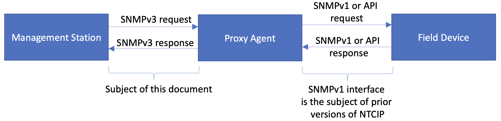
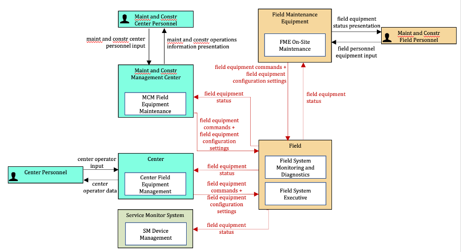
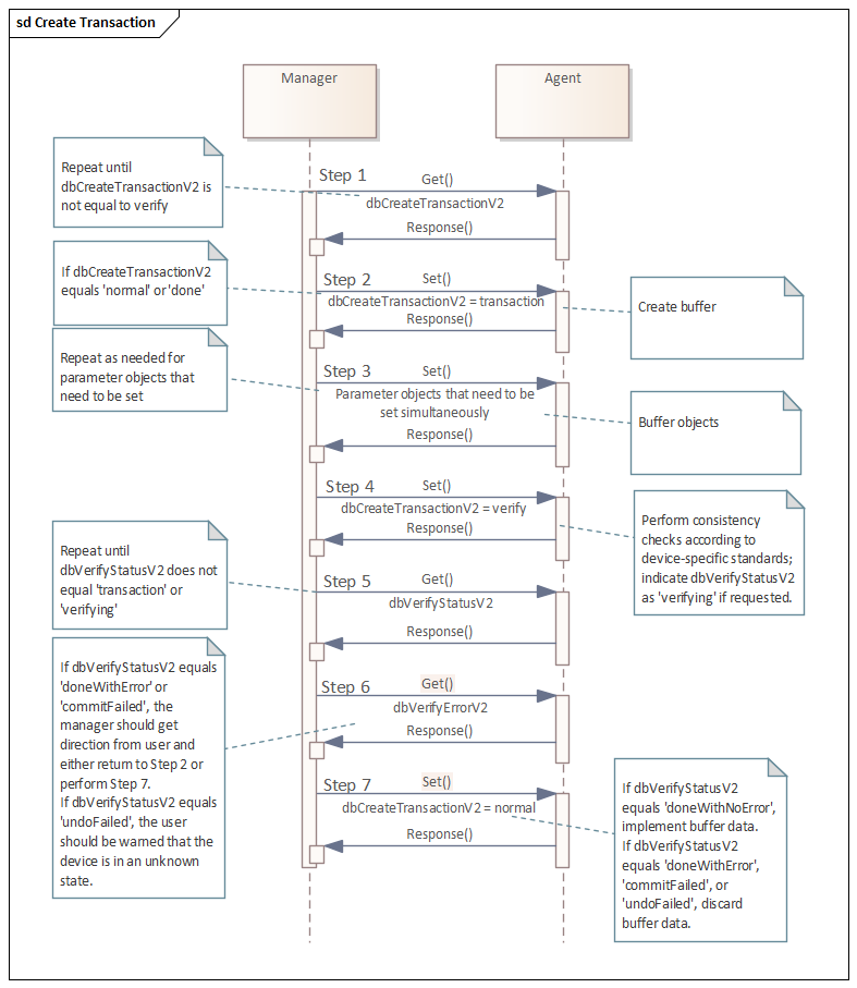
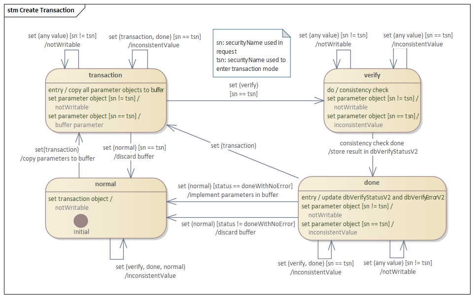
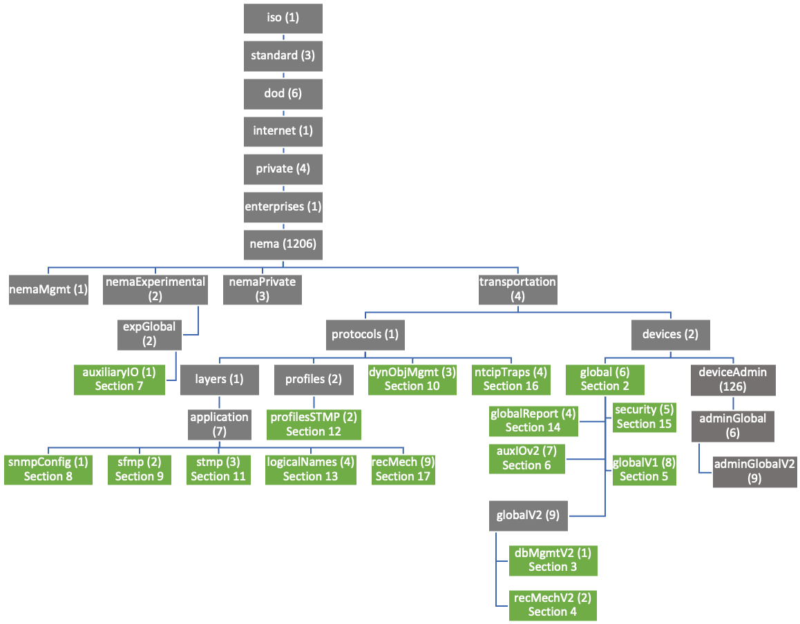
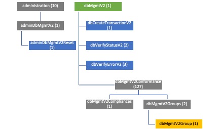
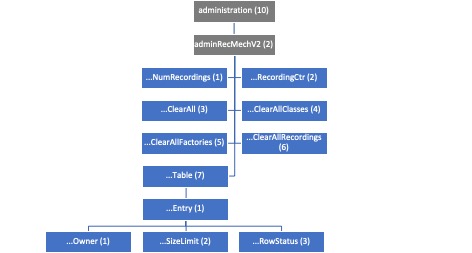
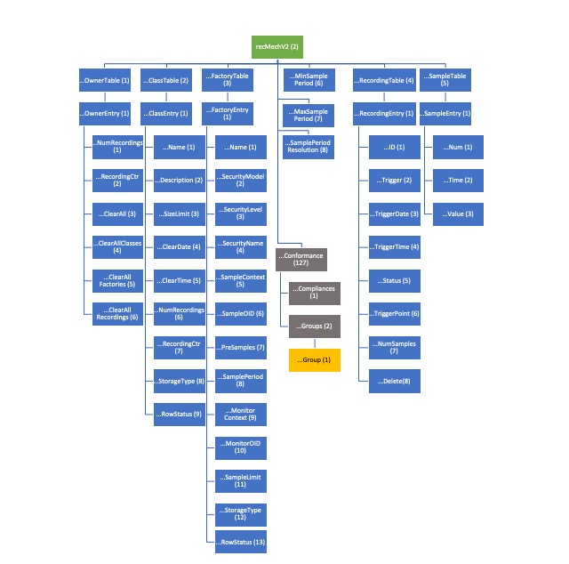
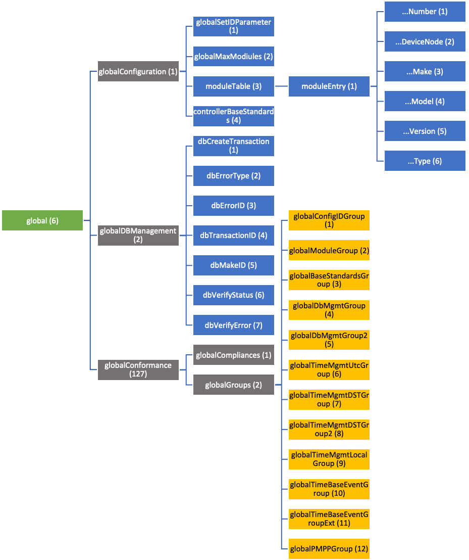
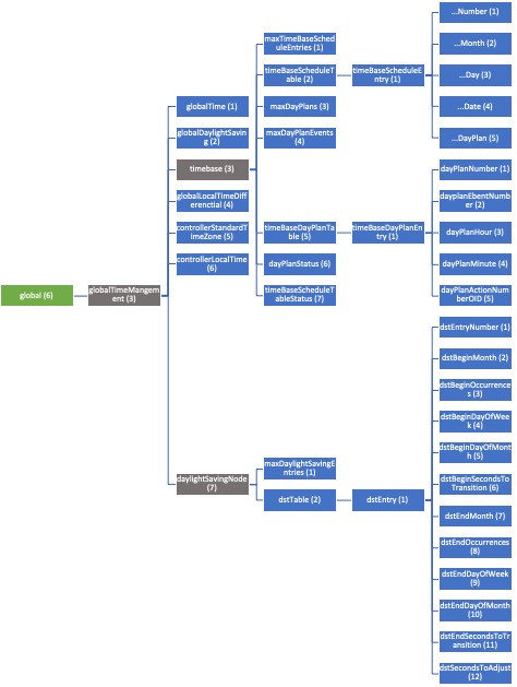
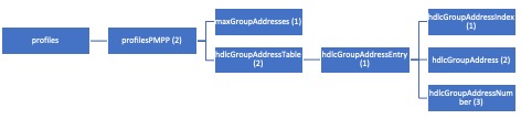
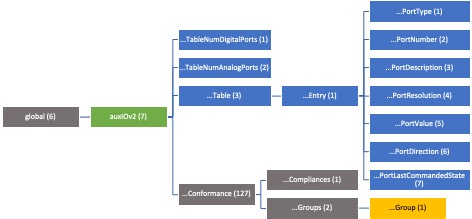

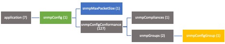
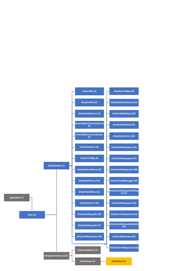
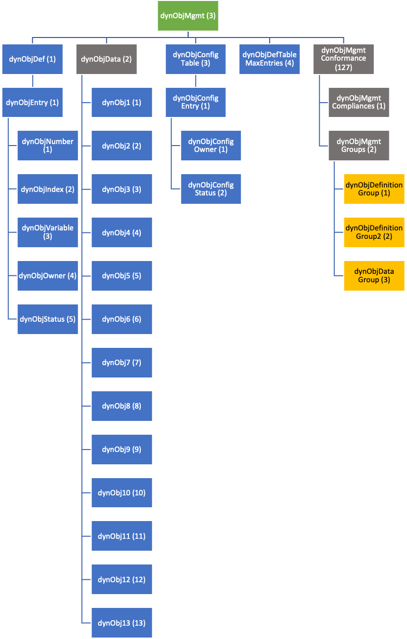
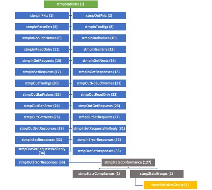
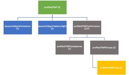
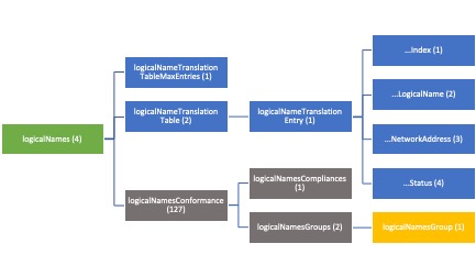
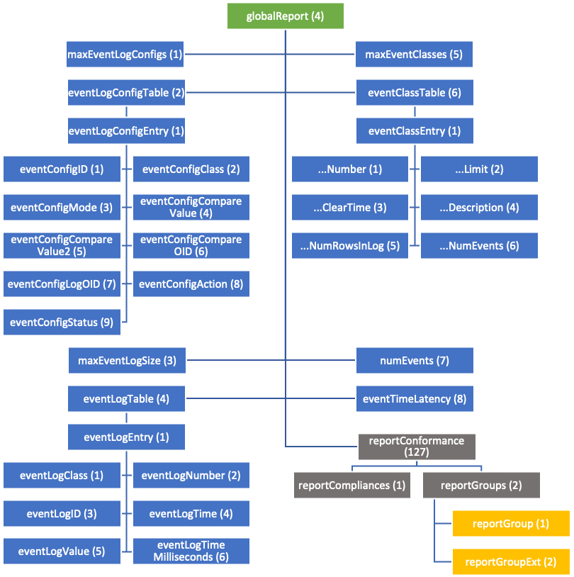
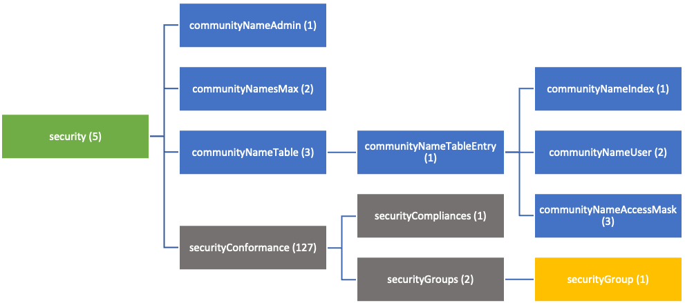
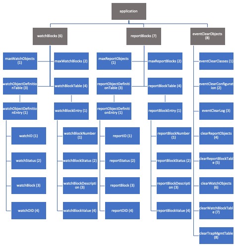
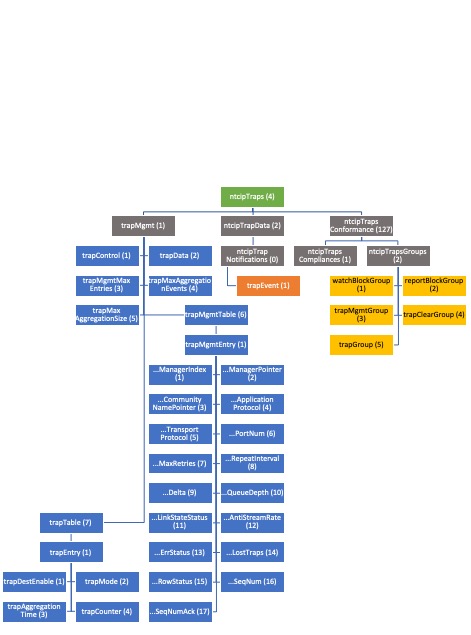
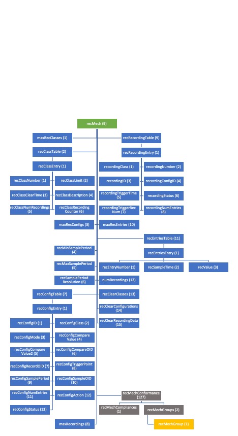
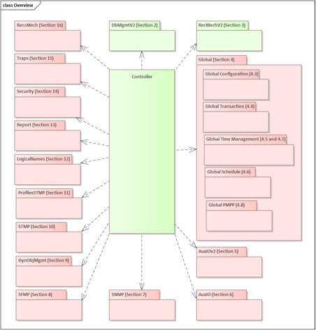
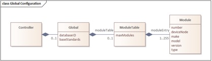
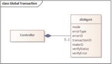
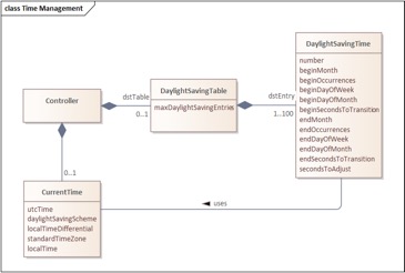
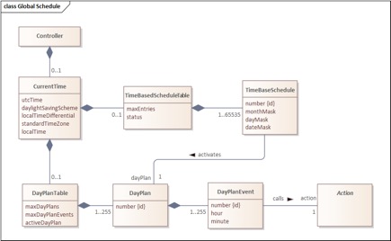
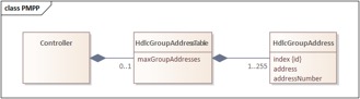
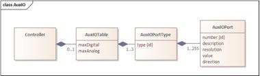
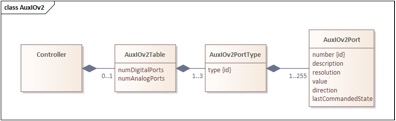
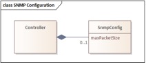
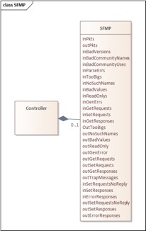
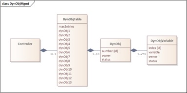
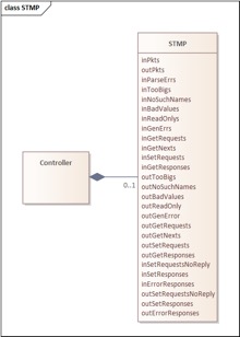
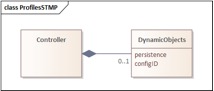
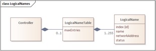
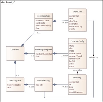
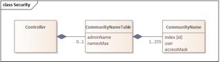
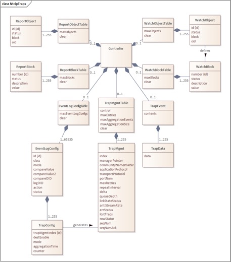
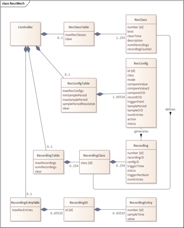
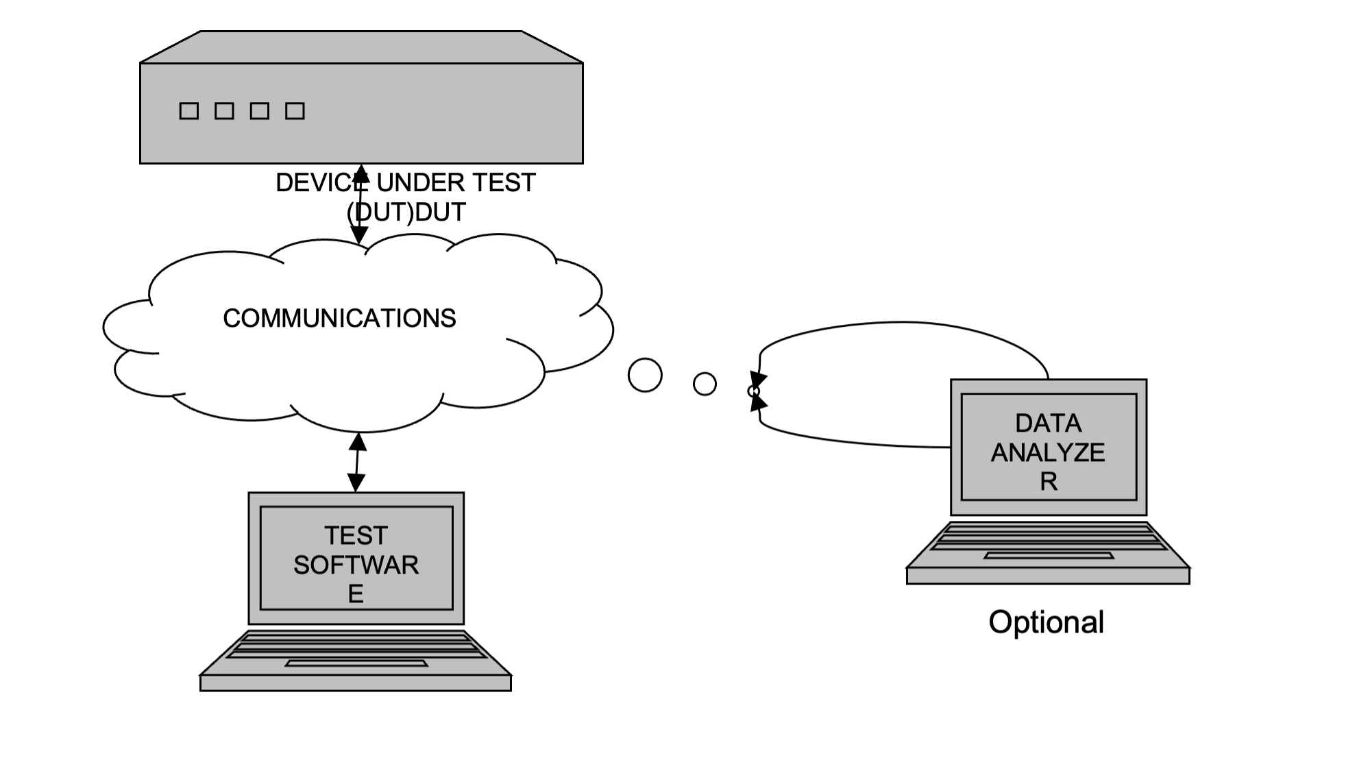
Get in touch
Phasellus convallis elit id ullamcorper pulvinar. Duis aliquam turpis mauris, eu ultricies erat malesuada quis. Aliquam dapibus, lacus eget hendrerit bibendum, urna est aliquam sem, sit amet imperdiet est velit quis lorem.
The bulk data request is a new feature for SNMPv3. Should this be included in this document?