| ID | Description | Links | Type | Name | Discussion |
|---|---|---|---|---|---|
| 26048_1-1 |
1 ScopeField devices are a key component in intelligent transport systems (ITS). Field devices include traffic signals, message signs, weather stations, traffic sensors, roadside equipment for connected ITS environments, etc. |
Text | |||
| 26048_1-2 |
The ISO 26048 series defines data that can be used to manage field devices, including device configuration, control, and monitoring. Field devices can be quite complex, necessitating the standardization of many data concepts for exchange. As such, the ISO 26048 series is divided into several individual parts. This document (Part 1) introduces the ISO 26048 series, provides normative content that applies to all subsequent parts, and defines data that is applicable to the management of a wide range of field devices. |
Text | |||
| 26048_1-933 |
The scope of the ISO 26048 series does not define the logic used by the management system, the underlying protocols used to exchange the defined data elements, or internal design of the field device. However, the ISO 26048 series does define place functional requirements on the interface and assumes an interface based on an SNMPv3 environment as specified by ISO 15784-2. |
Text | |||
| 26048_1-3 |
2 Normative referencesThe following documents are referred to in the text in such a way that some or all of their content constitutes requirements of this document. For dated references, only the edition cited applies. For undated references, the latest edition of the referenced document (including any amendments) applies. |
Text | |||
| 26048_1-4 |
IETF RFC 2578, Structure of Management Information Version 2 (SMIv2), April 1999. |
Reference | |||
| 26048_1-5 |
IETF RFC 2579, Textual Conventions for SMIv2, April 1999 |
Reference | |||
| 26048_1-918 |
IETF RFC 2580 |
Reference | |||
| 26048_1-6 |
3 Terms and definitionsFor the purposes of this document, the terms and definitions given in ISO/IEC/IEEE 24765, ISO 14812, IETF RFC 3411 and the following apply. |
Text | |||
| 26048_1-7 |
ISO and IEC maintain terminological databases for use in standardization at the following addresses: |
Text | |||
| 26048_1-8 |
ISO Online browsing platform: available at https://www.iso.org/obp |
Text | |||
| 26048_1-9 |
IEC Electropedia: available at http://www.electropedia.org/ |
Text | |||
| 26048_1-922 |
3.1 command generatorSNMP application that monitors and manipulates management information |
Term | |||
| 26048_1-921 |
3.2 command responderSNMP application that provides access to management information |
Term | |||
| 26048_1-15 |
3.3 field devicefixed or portable roadside module that includes an SNMP agent |
Term | |||
| 26048_1-16 |
3.4 fireto start a process when a trigger (3.13) value transitions from false to true |
Term | |||
| 26048_1-930 |
3.5 informnotification sent with an expectation of an acknowledgement |
Term | |||
| 26048_1-17 |
3.6 logregistry of snapshots within an SNMP agent that can be retrieved by an SNMP manager |
Term | |||
| 26048_1-20 |
3.7 notificationSNMP message from an SNMP agent that is generated independently from any explicit request |
Term | |||
| 26048_1-927 |
While a notification is not generated in response to any explicit request, it can be generated based on configured parameters stored within the SNMP agent. |
Note | |||
| 26048_1-923 |
3.8 notification originatorSNMP application that initiates asynchronous messages |
Term | |||
| 26048_1-924 |
3.9 notification receiverSNMP application that processes asynchronous messages |
Term | |||
| 26048_1-925 |
3.10 proxy forwarderSNMP application that forwards messages between entities |
Term | |||
| 26048_1-926 |
Proxy forwarder applications typically change the protocol or message model as a part of its functionality. |
Note | |||
| 26048_1-21 |
3.11 response timetime from the receipt of a Confirmed Class pduType by the command responder to the sending of the response PDU by the command responder |
Term | |||
| 26048_1-931 |
For the purpose of this document, the response time is measured at the application programming interface of the command responder. Any delays imposed within the lower layers are considered to be network delays and not included in the response time. |
Note | |||
| 26048_1-12 |
3.12 snapshotinformation captured when a trigger fires within an SNMP agent |
Term | |||
| 26048_1-13 |
A snapshot can be used in the generation of an SNMP notification or the creation of a new entry within a log. |
Note | |||
| 26048_1-10 |
3.13 SNMP agentSNMP entity containing one or more command responder and/or notification originator applications |
Term | |||
| 26048_1-920 |
3.14 SNMP applicationapplication that provides specific functional processing of SNMP management data |
Term | |||
| 26048_1-11 |
3.15 SNMP entityimplementation of one or more SNMP message processing models with one or more associated SNMP applications |
Term | |||
| 26048_1-919 |
An SNMP entity may also support one or more security models |
Note | |||
| 26048_1-928 |
3.16 SNMP field managerfixed or portable roadside module that includes an SNMP agent and an SNMP manager |
Term | |||
| 26048_1-929 |
SNMP field managers are field devices that can control other field devices. |
Note | |||
| 26048_1-18 |
3.17 SNMP managerSNMP entity containing one or more command generator and/or notification receiver applications |
Term | |||
| 26048_1-24 |
3.18 SNMP targetSNMP entity to which another SNMP entity can send requests or notifications |
Term | |||
| 26048_1-25 |
SNMP agents use the concept of a target to identify the SNMP manager to which a notification is to be sent. |
Note | |||
| 26048_1-26 |
Field devices can be configured to request data from other field devices to use in their expression or trigger logic. |
Note | |||
| 26048_1-27 |
Field devices can be configured to control other field devices in response to a trigger firing. |
Note | |||
| 26048_1-22 |
3.19 standardized requestget or set request that conforms to the specification of a request message included in a dialogue defined within a document approved by a standards development organization |
Term | |||
| 26048_1-23 |
EXAMPLE Subclause 8.1.2.8 (Monitor controller up time) of ISO 20684-2 defines a dialogue containing a get request, which contains sysUpTime, snmpEngineBoots, and snmpEngineTime.
|
Example | |||
| 26048_1-28 |
3.20 trapnotification sent without any expectation of an acknowledgement |
Term | |||
| 26048_1-29 |
3.21 triggercondition that evaluates to a Boolean value |
Term | |||
| 26048_1-30 |
4 Symbols and abbreviated terms |
Text | |||
| 26048_1-31 |
4.1 ARC-ITarchitecture reference for cooperative and intelligent transportation |
Abbreviated | |||
| 26048_1-33 |
4.2 ASCIIAmerican standard code for information interchange |
Abbreviated | |||
| 26048_1-34 |
4.3 ASN.1abstract syntax notation one |
Abbreviated | |||
| 26048_1-36 |
4.4 CCTconformance code table |
Abbreviated | |||
| 26048_1-38 |
4.5 C-PICSconsolidated protocols implementation conformance statement |
Abbreviated | |||
| 26048_1-40 |
4.6 (D)TLSdatagram transport layer security or transport layer security |
Abbreviated | |||
| 26048_1-42 |
4.7 FTRfeature-to-requirement |
Abbreviated | |||
| 26048_1-44 |
4.8 IETFInternet Engineering Task Force |
Abbreviated | |||
| 26048_1-45 |
4.9 IPinternet protocol |
Abbreviated | |||
| 26048_1-47 |
4.10 IPsecinternet protocol security |
Abbreviated | |||
| 26048_1-49 |
4.11 ISOInternational Organization for Standardization |
Abbreviated | |||
| 26048_1-51 |
4.12 ITSintelligent transport systems |
Abbreviated | |||
| 26048_1-53 |
4.13 ITS-SITS station |
Abbreviated | |||
| 26048_1-55 |
4.14 MIBmanagement information base |
Abbreviated | |||
| 26048_1-57 |
4.15 NTCIPnational transportation communications for ITS protocol |
Abbreviated | |||
| 26048_1-59 |
4.16 NTFneed-to-feature |
Abbreviated | |||
| 26048_1-61 |
4.17 OIDobject identifier |
Abbreviated | |||
| 26048_1-63 |
4.18 PDUprotocol data unit |
Abbreviated | |||
| 26048_1-65 |
4.19 RFCrequest for comments |
Abbreviated | |||
| 26048_1-67 |
4.20 RTMrequirements traceability matrix |
Abbreviated | |||
| 26048_1-69 |
4.21 SMIstructure and management of information |
Abbreviated | |||
| 26048_1-71 |
4.22 SNMPsimple network management protocol |
Abbreviated | |||
| 26048_1-73 |
4.23 TCPtransport control protocol |
Abbreviated | |||
| 26048_1-75 |
4.24 TLStransport layer security |
Abbreviated | |||
| 26048_1-77 |
4.25 UDPuser datagram protocol |
Abbreviated | |||
| 26048_1-79 |
4.26 USMuser-based security model |
Abbreviated | |||
| 26048_1-82 |
5 Conventions and architecture |
Centered Text | |||
| 26048_1-80 |
5.1 ISO maintenance portalThis document is accompanied by electronic attachments that form an integral part of this document and are available for download through the ISO maintenance portal at: https://standards.iso.org/iso/ts/26048/-1/ed-1/en. |
Text | |||
| 26048_1-81 |
5.2 MIB FilesThis document normatively incorporates one or more management information bases (MIBs), which conform to RFC 2578, RFC 2579, and RFC 2580. These files are defined in ASCII text files, which can be accessed electronically from the ISO maintenance portal as indicated in !~Section 80~!. |
Text | |||
| 26048_1-83 |
The filename for each component MIB is the name of the MIB with a ".mib" extension. |
Text | |||
| 26048_1-84 |
5.3 ASN.1This document contains references to and explanations of ASN.1 data concepts within its text. In all cases, the ASN.1 terms are presented in a fixed width font (e.g. !<pre>!such as this!</pre>!) to distinguish these terms from normal English. |
Text | |||
| 26048_1-940 |
5.4 ConformanceConformance to this document is defined by the traceability tables available through the ISO maintenance portal, including the NTF traceability table, the FTR traceability table, and the RTM. |
Text | |||
| 26048_1-941 |
Each item of conformance in this document is worded in a manner as if has been selected in these tables. For example requirements are stated as simple "shall" statements even if they are listed as optional in the FTR traceability table. The applicability of each item of conformance is defined in the traceability tables. |
Text | |||
| 26048_1-85 |
5.5 SNMP terminologyTerminology between the different versions of SNMP is slightly different. For the purposes of the ISO 26048 series, the terminology of SNMPv3 is adopted. |
Text | |||
| 26048_1-932 |
5.6 Architecture |
Text | |||
| 26048_1-86 |
5.6.1 ITS servicesThe ISO 26048 series defines mechanisms by which field devices can be monitored, configured and controlled. Field devices may be used to support almost any ITS service, defined in ISO 14813-1, with a roadside component. |
Text | |||
| 26048_1-87 |
5.6.2 Functional view of interfaceThe ISO 26048 series is concerned with defining the data concepts used to manage a field device. The data concepts defined in this document have been defined based on needs derived from an analysis of various services contained within the architecture reference for cooperative and intelligent transportation (ARC-IT)[19]. |
Text | |||
| 26048_1-88 |
5.6.3 Physical viewFigure 1 depicts the physical view of this interface using the graphical conventions defined by ARC-IT [19] and also documented in ISO 14813-5:2020, Annex B. |
Text | |||
| 26048_1-90 | Figure | Physical view of interface | |||
| 26048_1-91 |
The management system of the field device is shown in grey indicating that it can be any type of physical object, such as a central system, another field device, a maintenance laptop or any other device that supports the defined interface. |
Text | |||
| 26048_1-92 |
The field device is shown in orange, indicating that it is located in the field (e.g. along the roadside). It shall have a connection to the management system and may have any number of connections to other ITS stations or external systems. |
Text | |||
| 26048_1-93 |
The figure indicates two information transfers between these physical objects. The first is the "configuration and commands" information flow from the management system to the field device. The second is the "status and notifications" information flow from the field device to the management system. Both flows are shown in green indicating that authentication is required, and both are shown with a single arrowhead indicating a unicast transfer. |
Text | |||
| 26048_1-95 |
This document is based on the use of SNMP, which implements a GET/SET paradigm where there is a command generator and a command responder. However, a single SNMP entity can act as both a command generator (e.g. sending requests to other field devices) and as a command responder (e.g. responding to requests from a centre or other field device) simultaneously. The term "SNMP field manager" is used to specify this type of dual-function device. |
Note | |||
| 26048_1-96 |
5.6.4 Communications viewFigure 2 depicts how the ISO 26048 series is intended to relate to other standards using the ITS Station architecture, as defined in ISO 21217. |
Text | |||
| 26048_1-97 | Figure | Typical communications stack | |||
| 26048_1-98 |
Part 1 of the ISO 26048 series (this document) defines features that are a part of the management entity of the ITS station (ITS-S) architecture. This includes management information that indirectly supports device-specific functionality. The management layer typically also supports other data to manage the communications stack as defined by a variety of SNMPv3 MIBs (e.g., the management information referenced by ISO 15784-2). |
Text | |||
| 26048_1-99 |
!~Section 819~! defines the UTC clock feature, which can be used to support end-device functionality, such as selecting a time-of-day action plan. |
Example | |||
| 26048_1-100 |
Other parts of the ISO 26048 series will address device-specific functionality and are considered part of the definition of ITS-S application entity. |
Text | |||
| 26048_1-101 |
ISO 26048-3 is expected to define management information related to controlling and monitoring a variable message sign. |
Example | |||
| 26048_1-102 |
The information defined for the management entity and ITS-S application entity can theoretically be exchanged over any communications stack, but is designed to be exchanged using SNMPv3, as described in ISO 15784-2, which requires support for the Transport Layer Security (TLS) Transport Model, as defined in RFC 6353. These standards are typically exchanged using well-known internet protocols, such as UDP/IP or TCP/IP over any number of access layers. |
Text | |||
| 26048_1-934 |
5.7 OutlineThis document presents a separate section for each step in the systems engineering process, as described as follows: |
Text | |||
| 26048_1-935 |
User needs — Each user need describes a capability that a management system might need to perform. User needs are written from the perspective of a management system and include a justification for the need. |
List Level 1 | |||
| 26048_1-942 |
High-level design — Each user need is analyzed and decomposed into a set of features. Features are can be separately managed and can potentially support multiple user needs. The applicability of each feature within a user need is defined by the need-to-feature (NTF) traceability table, which is available on the ISO maintenance portal as discussed in !~Section 80~!. |
List Level 1 | |||
| 26048_1-936 |
Requirements — Each feature is decomposed into a set of formal requirements, including data exchange requirements and other requirements (e.g., performance, constraints). The applicability of each requirement within a feature is defined by the feature-to-requirement (FTR) traceability table, which is available on the ISO maintenance portal as discussed in !~Section 80~!. |
List Level 1 | |||
| 26048_1-937 |
Dialogues — Each data exchange requirement is implemented using exactly one standardized dialogue coupled with a defined set of objects. The standardized dialogue is defined as a sequence of SNMP operations. The traceability between data exchange requirements and their associated dialogues are defined in the requirements traceability matrix (RTM), which is available on the ISO maintenance portal as discussed in !~Section 80~!. |
List Level 1 | |||
| 26048_1-938 |
Management Information Base — Each data exchange requirement is satisfied using one or more managed objects to be included in the associated dialogue. Objects are instances of object-types, which are defined in electronic MIB(s). The traceability between each data exchange requirement and the associated object-types are defined in the RTM. The RTM and MIBs defined by this document are available on the ISO maintenance portal as discussed in !~Section 80~!. Other MIBs (e.g., those in RFCs) are available in the referenced normative reference. |
List Level 1 | |||
| 26048_1-103 |
6 User needs |
Text | |||
| 26048_1-280 |
6.1 Control access to dataA management system needs to ensure that users are only allowed to access data according to the authority that they have been granted. |
Fulfilled by:
26048_1-979 View-based access control model (VACM) f…
|
User Need | ||
| 26048_1-264 |
6.2 Manage the field deviceA management system needs to be able to identify and monitor the overall capabilities and health of each field device controller and its cabinet to discover anomalous conditions that can affect its operation or security. This will assist the management system in confirming which controller(s) are in a cabinet, as well as the type and specific instance of each controller and the high-level capabilities offered by the device as well as performing proper maintenance actions. |
Fulfilled by:
26048_1-345 Cabinet feature
26048_1-283 Controller feature
|
User Need | ||
| 26048_1-265 |
EXAMPLE A management system that is receiving unexpected errors can verify which device it is communicating with as a part of a debugging process and can determine if the device configuration has been changed since its last known state so that the appropriate action can be taken if access has not been authorized. |
Example | |||
| 26048_1-269 |
6.3 Monitor cabinet |
Text | |||
| 26048_1-270 |
6.3.1 Monitor cabinet doorsA management system needs to be able to monitor the open/close status of each cabinet door to determine when equipment is being physically accessed. |
Fulfilled by:
26048_1-359 Cabinet doors
26048_1-324 Supplemental roadside sensors and actuat…
|
User Need | ||
| 26048_1-271 |
6.3.2 Monitor and control cabinet fansA management system needs to be able to monitor and control the on/off status of each cabinet fan to manage the cabinet temperature. |
Fulfilled by:
26048_1-366 Cabinet fans
26048_1-324 Supplemental roadside sensors and actuat…
|
User Need | ||
| 26048_1-272 |
6.3.3 Monitor and control cabinet heatersA management system needs to be able to monitor and control the on/off status of each cabinet heater to manage the cabinet temperature. |
Fulfilled by:
26048_1-374 Cabinet heaters
26048_1-324 Supplemental roadside sensors and actuat…
|
User Need | ||
| 26048_1-273 |
6.3.4 Monitor cabinet humidityA management system needs to be able to monitor the relative humidity within the cabinet to disable the controller or subsystems in extreme conditions. |
Fulfilled by:
26048_1-382 Cabinet humidity
26048_1-324 Supplemental roadside sensors and actuat…
|
User Need | ||
| 26048_1-274 |
6.3.5 Monitor cabinet temperatureA management system needs to be able to monitor the air temperature inside the cabinet to determine when climate control equipment should be activated and/or to disable equipment to prevent overheating. |
Fulfilled by:
26048_1-389 Cabinet temperature
26048_1-324 Supplemental roadside sensors and actuat…
|
User Need | ||
| 26048_1-275 |
6.3.6 Monitor cabinet mains powerA management system needs to be able to monitor the status of the incoming mains power line, which is typically provided by the power grid to detect when this power is lost or becomes unstable. |
Fulfilled by:
26048_1-396 Cabinet mains power
26048_1-324 Supplemental roadside sensors and actuat…
|
User Need | ||
| 26048_1-276 |
6.3.7 Monitor cabinet battery powerA management system needs to be able to monitor the status of the battery power system to determine the quality of power and amount of charge available. |
Fulfilled by:
26048_1-405 Cabinet battery
26048_1-324 Supplemental roadside sensors and actuat…
|
User Need | ||
| 26048_1-277 |
6.3.8 Monitor cabinet generator powerA management system needs to be able to monitor the status of the cabinet generator power to determine the quality of power being produced and the fuel reserve. |
Fulfilled by:
26048_1-416 Cabinet generator
26048_1-324 Supplemental roadside sensors and actuat…
|
User Need | ||
| 26048_1-278 |
6.3.9 Monitor cabinet solar powerA management system needs to be able to monitor the status of the solar power system to determine the amount of power being generated. |
Fulfilled by:
26048_1-429 Cabinet solar power
26048_1-324 Supplemental roadside sensors and actuat…
|
User Need | ||
| 26048_1-279 |
6.3.10 Monitor cabinet wind powerA management system needs to be able to monitor the status of the wind power system to determine the amount of power being generated. |
Fulfilled by:
26048_1-438 Cabinet wind power
26048_1-324 Supplemental roadside sensors and actuat…
|
User Need | ||
| 26048_1-598 |
6.4 Receive notification of triggers firingWhen user-defined triggers fire, one or more independent management systems need to receive real-time notifications containing user-defined information. This will allow a management system to immediately become aware of information that can affect its operation or security without burdening the communications channel with frequent polling for data that seldom changes. Multiple triggers can be monitored with different systems being notified based on the type of condition. |
Conditionally met by:
Conditionals-23 Conditional Trigger
Conditionals-25 Day Plan Triggers
Conditionals-24 Scheduled Triggers
Fulfilled by:
26048_1-648 Notification feature
26048_1-860 SNMP target feature
Includes option groups:
OptionGroups-9 Trigger Options (1..*)
Optionally fulfilled by:
26048_1-884 Dynamic object feature
26048_1-712 Notification aggregator
|
Text | ||
| 26048_1-600 |
EXAMPLE 1 A management system wants to be immediately notified when the cabinet door opens so that an appropriate response can be initiated if the access is unauthorized. |
Example | |||
| 26048_1-601 |
EXAMPLE 2 A management system wants to have the maintenance system notified when the cabinet door opens and have the traffic management system notified when a new message is displayed on a sign. |
Example | |||
| 26048_1-730 |
6.5 Log user-defined snapshotsOne or more independent management systems need to be able to configure a field device to log snapshots for later retrieval. This user need allows a management system to configure conditions that will automatically trigger the logging of snapshot data along with a timestamp. A management system can configure multiple triggers and multiple management systems can configure the same or different conditions. |
Conditionally met by:
Conditionals-23 Conditional Trigger
Conditionals-25 Day Plan Triggers
Conditionals-24 Scheduled Triggers
Fulfilled by:
26048_1-819 UTC clock
26048_1-745 Logging feature
Includes option groups:
OptionGroups-9 Trigger Options (1..*)
Optionally fulfilled by:
26048_1-884 Dynamic object feature
|
User Need | ||
| 26048_1-732 |
EXAMPLE 1 A management system wants the device to record the number of vehicles counted every 15 min so that the management system can retrieve the information at the end of each day. |
Example | |||
| 26048_1-733 |
EXAMPLE 2 A management system wants to retrieve diagnostic-related snapshots (e.g., cabinet door open) separately from operation-related snapshots (e.g., a new message on a sign). This can be due to internal logic, or it can be because two separate management systems communicate with the device. |
Example | |||
| 26048_1-1047 |
6.6 Record a series of snapshotsOne or more independent management systems need to be able to configure a field device to record a series of snapshots for later retrieval so that conditions can be recreated. This user need allows a management system to configure conditions that will automatically trigger the recording of a series of snapshots, each with a timestamp. |
Conditionally met by:
Conditionals-23 Conditional Trigger
Conditionals-25 Day Plan Triggers
Conditionals-24 Scheduled Triggers
Fulfilled by:
26048_1-999 Recording feature
Includes option groups:
OptionGroups-9 Trigger Options (1..*)
Optionally fulfilled by:
26048_1-884 Dynamic object feature
|
User Need | ||
| 26048_1-1048 |
A management system wants the device to record the count of the number of vehicles approaching an intersection each second after the signal changes to yellow to produce a better estimate of the delays at the signal. |
Example | |||
| 26048_1-787 |
6.7 Issue trigger-based commandsOne or more independent management systems need to be able to configure an SNMP field manager to send a command to an SNMP agent when user-defined conditions are detected by the SNMP field manager. This will allow the field manager to alter the state of other field devices as triggers fire without burdening the communications channel between the centre and field location. |
Conditionally met by:
Conditionals-23 Conditional Trigger
Conditionals-25 Day Plan Triggers
Conditionals-24 Scheduled Triggers
Fulfilled by:
26048_1-800 Command feature
Includes option groups:
OptionGroups-9 Trigger Options (1..*)
Optionally fulfilled by:
26048_1-860 SNMP target feature
|
User Need | ||
| 26048_1-789 |
The SNMP field manager and SNMP agent can be in the same field device. |
Note | |||
| 26048_1-790 |
EXAMPLE A management system wants to configure a field manager to automatically display a message (on one device) whenever ice is detected on the roadway (by another device). |
Example | |||
| 26048_1-1049 |
6.8 Configure a complex deviceFor devices that have extensive inter-relationships among configuration parameters, a management system needs to provide all necessary configuration updates prior to the new configuration being validated and implemented. |
Fulfilled by:
26048_1-984 Transaction feature
|
User Need | ||
| 26048_1-1050 |
A phased-based traffic signal controller has many objects that are safety critical. When reconfiguring a traffic signal controller, it is important to ensure that the values are internally consistent to prevent any potential for unsafe operation. The number of inter-related parameters typically exceed what can be delivered in a single SNMP message. As a result, a distinct mechanism is required to buffer the initial set of changes and to perform validation once all parameters have been set. |
Example | |||
| 26048_1-817 |
6.9 Efficient exchange of dataOne or more management systems need to repeatedly perform requests related to the same group of managed object values. Normal SNMP operations require the complete object identifier (OID) of every object value to be specified in each request. These OIDs are often 10-20 octets in length, which can significantly increase communications overhead when the values being retrieved are small (e.g., one-octet INTEGERs). This document defines a mechanism to allow a manager to configure dynamic objects, which can then be used to interact with multiple managed objects via a single OID. |
Fulfilled by:
26048_1-884 Dynamic object feature
|
User Need | ||
| 26048_1-962 |
A management system polls a specific group of integer-based objects periodically to monitor the operation of a field device. The communication network used to connect to the field device includes a link that charges for data usage. Rather than requesting each status object individually, the management system wishes to configure a structure that can be repeatedly requested using less overhead. |
Example | |||
| 26048_1-943 |
7 High-level design |
Text | |||
| 26048_1-944 |
7.1 Control access to data design overviewData access is controlled using the view-based access control model (VACM), as defined in RFC 3415, coupled with a design of the OID tree to ensure that administrators can easily restrict access to branches of the tree based on intended access rights. |
Text | |||
| 26048_1-965 |
Configuring the VACM consists of the following major steps: |
Text | |||
| 26048_1-967 |
discovering available contexts within the field device; |
List Level 1 | |||
| 26048_1-969 |
configuring MIB views; |
List Level 1 | |||
| 26048_1-966 |
assigning each user to VACM group; and |
List Level 1 | |||
| 26048_1-968 |
configuring access permissions for each group. |
List Level 1 | |||
| 26048_1-964 |
A context represents a complete instantiation of management information. A field device can contain a one or more contexts. For example, a single field device can be used to control the display for two signs (e.g., one facing north and one facing south). Such a device can define two contexts, one for each sign. Each context would contain a complete instance of the MIB with unique object instances for each. When appropriate, object instance values can be linked. For example, each context would likely have a different value for the currently displayed message while both contexts should have a common interpretation of the time of day. Contexts are defined by the device and cannot be configured by a management system. |
Text | |||
| 26048_1-973 |
Many field devices contain a single context and use an empty string to identify the context. |
Note | |||
| 26048_1-971 |
A MIB view represents a subset of objects available within a device to which a user should have access. A MIB view is configured by identifying portions of the OID tree to which access should be granted or prohibited. |
Text | |||
| 26048_1-978 |
A branch of the OID tree that should only be accessible to administrators can be excluded from a MIB view intended to be used by technicians. |
Example | |||
| 26048_1-963 |
A VACM group represents zero or more authenticated users, where each user is identified by a security name and security model pair. When requests are received, the SNMP engine determines the security name and security model and uses the information to determine which group's access rights to use. The process used to authenticate this information is defined separately by the security model. |
Text | |||
| 26048_1-974 |
All field technicians can be assigned to the same group. |
Example | |||
| 26048_1-970 |
Once the necessary contexts, VACM groups, and MIB views are defined, access can be configured for each VACM group. The configuration includes a separate assignments based on the type of request (e.g., get, set) as well as the security model and level (e.g., whether encryption is used). |
Text | |||
| 26048_1-977 |
The same user can be granted different access rights for a context related to a north facing sign than for a context related to a south facing sign. |
Example | |||
| 26048_1-976 |
The same user can be assigned different MIB views for get requests than for set requests. |
Example | |||
| 26048_1-975 |
The same user can be granted different access using encryption than when not using encryption. |
Example | |||
| 26048_1-945 |
7.2 Manage the field device design overviewMonitoring the field device involves both the field device feature and the cabinet feature. The object-types included within these features primarily consists of information that is either read-only or writable with no or minimal interactions with other management information from a semantic perspective. |
User Need | |||
| 26048_1-950 |
7.3 Monitor cabinet |
Text | |||
| 26048_1-951 |
7.3.1 Monitor cabinet doors design overviewMonitoring cabinet doors is achieved through the use of the cabinet door feature coupled with the supplemental roadside sensors and actuators feature. |
User Need | |||
| 26048_1-952 |
7.3.2 Monitor and control cabinet fans design overviewMonitoring and controlling cabinet fans is achieved through the use of the cabinet fans feature coupled with the supplemental roadside sensors and actuators feature. |
User Need | |||
| 26048_1-953 |
7.3.3 Monitor and control cabinet heaters design overviewMonitoring and controlling cabinet heaters is achieved through the use of the cabinet heaters feature coupled with the supplemental roadside sensors and actuators feature. |
User Need | |||
| 26048_1-954 |
7.3.4 Monitor cabinet humidity design overviewMonitoring cabinet humidity is achieved through the use of the cabinet humidity feature coupled with the supplemental roadside sensors and actuators feature. |
User Need | |||
| 26048_1-955 |
7.3.5 Monitor cabinet temperature design overviewMonitoring cabinet temperature is achieved through the use of the cabinet temperature feature coupled with the supplemental roadside sensors and actuators feature. |
User Need | |||
| 26048_1-956 |
7.3.6 Monitor cabinet mains power design overviewMonitoring cabinet mains power is achieved through the use of the cabinet mains power feature coupled with the supplemental roadside sensors and actuators feature. |
User Need | |||
| 26048_1-957 |
7.3.7 Monitor cabinet battery power design overviewMonitoring cabinet battery power is achieved through the use of the cabinet battery power feature coupled with the supplemental roadside sensors and actuators feature. |
User Need | |||
| 26048_1-958 |
7.3.8 Monitor cabinet generator power design overviewMonitoring cabinet generator power is achieved through the use of the cabinet cabinet generator feature coupled with the supplemental roadside sensors and actuators feature. |
User Need | |||
| 26048_1-959 |
7.3.9 Monitor cabinet solar power design overviewMonitoring cabinet solar power is achieved through the use of the cabinet solar power feature coupled with the supplemental roadside sensors and actuators feature. |
User Need | |||
| 26048_1-960 |
7.3.10 Monitor cabinet wind power design overviewMonitoring cabinet wind power is achieved through the use of the cabinet wind power feature coupled with the supplemental roadside sensors and actuators feature. |
User Need | |||
| 26048_1-612 |
7.4 Receive notification of triggers firing design overviewReceiving notifications is achieved using a variety of features as depicted in !~Figure 613~!. |
Text | |||
| 26048_1-613 | Figure | Conceptual overview of notifications | |||
| 26048_1-614 |
When a trigger (!~Section 981~!) fires, it calls an action manager (!~Section 540~!), which may direct the call to the notification factory. When called, the notification factory captures the current value of a specified object and stores this value in a notification snapshot along with an identifier of the condition that initiated the snapshot and timestamp. The object value recorded may be an !@fdCompositeObjectValue@! (ISO26048-1-DynObj.mib), which can consolidate the values of multiple subordinate objects into a single SNMP object. The notification factory then passes the notification snapshot to the notification channel along with information about how the notification snapshot is to be handled (e.g., aggregated or not). Multiple notification factories may use the same notification channel. If the notification snapshot is flagged for aggregation, it is passed to the notification aggregator; otherwise the notification channel assigns the notification snapshot to an appropriate one-off notification packet. The notification aggregator combines notification snapshots into a single notification packet, which serves to reduce overall communications overhead. The notification aggregator conceptually manages two aggregate notification packets: one that requires acknowledgements (i.e., an SNMP inform) and another that does not (i.e., a SNMP trap). Notification snapshots from different notification factories can be combined into a single notification packet. Once a notification packet is completed, it is sent back to the notification channel for transmission to the SNMP target. Once a notification packet is ready to send, the notification channel sends the notification packet to the SNMP target while ensuring that the anti-streaming rate is not exceeded, which allows temporary queueing of notifications so that they do not overwhelm the communications channel. Finally, as per the rules of SNMPv3, trap messages are unacknowledged and inform messages are acknowledged. The acknowledgement process is handled according to standard SNMPv3 rules (complete with timeout and retry logic). |
Text | |||
| 26048_1-742 |
7.5 Log user-defined snapshots design overviewLogging snapshots is achieved using a variety of features as depicted in !~Figure 743~!. |
Text | |||
| 26048_1-743 | Figure | Conceptual overview of logging | |||
| 26048_1-744 |
When a trigger (!~Section 981~!) fires, it calls an action, which may direct the call to a log snapshot factory. When called, the log snapshot factory captures a defined object value from the device and records this in a new entry in the identified log class based on configured parameters. While the snapshot only records a single object instance value, the object instance can be an instance of !@fdDynObjCurrentValue@!, which can contain multiple object instance values packaged in an efficient manner. The log can be managed (e.g., fully or partially cleared) using the log manager. The log manager also reports statistics for the log. |
Text | |||
| 26048_1-1051 |
7.6 Record a series of snapshots design overviewLogging snapshots is achieved using a variety of features as depicted in !~Figure 1053~!. |
Text | |||
| 26048_1-1053 | Figure | Conceptual overview of recordings | |||
| 26048_1-1054 |
When a trigger (!~Section 981~!) fires, it calls an action, which may direct the call to a recording factory. When called, if the recording is configured to include pre-event snapshots, the recording factory moves the configured number of previously recorded snapshots, to the extent that they are available, into the recording log. The recording factory continues capturing snapshots per the configuration and stores each into the recording log. While each snapshot only records a single object instance value, the object instance can be an instance of !@fdDynObjCurrentValue@!, which can contain multiple object instance values packaged in an efficient manner. The recording can be managed (e.g., fully or partially cleared) using the recording manager. The recording manager also reports statistics for the recording log. |
||||
| 26048_1-797 |
7.7 Issue trigger-based commands design overviewLogging snapshots is achieved using a variety of features as depicted in !~Figure 798~!. |
Text | |||
| 26048_1-798 | Figure | Conceptual overview of commands | |||
| 26048_1-799 |
When a trigger (!~Section 981~!) fires, it calls an action, which may direct the call to a command factory. When called, the SNMP field manager sends the configured SNMP set request to the identified SNMP target using the configured SNMP target parameters. |
Text | |||
| 26048_1-1052 |
7.8 Configure a complex device design overviewConfiguring a complex device starts by placing the field device into the transaction mode, which logically creates a copy of the current configuration in a buffer and all set operations on parameter objects from the same management system that started transaction mode are stored in the buffer. Any request from another management system to change any parameter is rejected. |
Text | |||
| 26048_1-1064 |
Once the initiating management system has completed its proposed changes, it should direct the field device to verify the buffered parameters to ensure that the settings pass all internal consistency checks. The checks can take time and the field device will transition to a done state at the end of the process. The management station can then retrieve the error code and if there were no errors, it can implement the buffered configuration. |
Text | |||
| 26048_1-961 |
7.9 Efficient data exchange design overviewNormal SNMP operations consist of get and set operations on atomic elements, which are identified by a 10-20 octet identifier. Within ITS, a large percentage of the atomic elements that are exchanged are integer values that are encoded in one to four octets. As a result, identifiers consume a significant percentage of the size of each normal SNMP message exchanged within ITS unless a more efficient design is used. |
Text | |||
| 26048_1-1065 |
The solution is provided with the dynamic object feature, which allows a management system to configure a dynamic object to be a reference to a list of object instances supported by the device. Once configured, the management system can reference the single identifier for the dynamic object as a shorthand reference to the list of object instances associated with that dynamic object configuration. |
Text | |||
| 26048_1-1066 |
As an added efficiency, the management system can configure the dynamic object to encode its value using the octet encoding rules (OER) rather than the basic encoding rules (BER), which is typically used by SNMP. The results in eliminating additional overhead from the encoding. |
Text | |||
| 26048_1-981 |
7.10 Triggers |
Text | |||
| 26048_1-982 |
7.10.1 GeneralA device can establish triggers based on a number of factors. This document defines three trigger mechanisms but does not restrict the development of other trigger mechanisms. |
Text | |||
| 26048_1-483 |
7.10.2 Scheduled triggers design overviewThe design of the schedule triggers user need is depicted in !~Figure 484~!. |
Text | |||
| 26048_1-484 | Figure | Schedule triggers | |||
| 26048_1-485 |
Each trigger schedule defines time(s) at which a trigger will fire. The trigger schedule uses the local clock to determine when to fire the trigger and thereby implement the action(s). The local clock is based on the UTC clock modified by the time zone and optionally by the daylight saving (i.e., summer) time (DST). When a trigger fires, it causes the action manager to perform one or more defined actions. |
Text | |||
| 26048_1-471 |
7.10.3 Day plan triggers design overviewThe design of the schedule triggers user need is depicted in !~Figure 472~!. |
Text | |||
| 26048_1-472 | Figure | Schedule day plans | |||
| 26048_1-473 |
The day plan schedule selects a specific day plan based on the month, day of month, and day of week. Each day plan consists of a description and series times at which a trigger will fire during the day. The day plan schedule and day plan trigger both use the local clock to determine the current local time. The local clock is based on the UTC clock modified by the time zone and optionally by the daylight saving time (DST). When a day plan trigger fires, it causes the action manager to perform one or more defined actions. |
Text | |||
| 26048_1-496 |
7.10.4 Condition-based triggers design overviewThe design of the schedule triggers user need is depicted in !~Figure 497~!. |
Text | |||
| 26048_1-497 | Figure | Condition-based triggers | |||
| 26048_1-498 |
Each conditional trigger is is configured to monitor a value of an object instance and to fire when a configured condition occurs. The value of the object instance can be configured to reference: |
Text | |||
| 26048_1-499 |
local SNMP data (i.e., any data from the local field device); or |
List Level 1 | |||
| 26048_1-500 |
data from an SNMP target (i.e., an external field device). |
List Level 1 | |||
| 26048_1-501 |
When the conditions defined by the trigger occur (e.g., the value exceeding a defined threshold), the trigger fires causing the action manager to perform one or more defined actions. |
Text | |||
| 26048_1-104 |
8 Requirements |
Text | |||
| 26048_1-540 |
8.1 Action feature |
Refined by:
26048_1-553 Configure an action owner
26048_1-544 Configure an action group
26048_1-1077 Configure an action
26048_1-554 Confirm action owner configuration
26048_1-545 Confirm action group configuration
26048_1-1078 Confirm action configuration
26048_1-550 Delete action group
26048_1-551 Delete action
26048_1-548 Toggle action group
26048_1-549 Toggle action
26048_1-552 Retrieve summary action statistics
26048_1-555 Retrieve action owner statistics
26048_1-546 Retrieve action group statistics
26048_1-1079 Retrieve action statistics
26048_1-1080 Validate access upon action activation
26048_1-1081 Validate access upon action being called
Fulfills:
Conditionals-23 Conditional Trigger
Conditionals-25 Day Plan Triggers
Conditionals-24 Scheduled Triggers
|
Feature | ||
| 26048_1-541 |
8.1.1 Action feature definitionThe action feature associates the firing of a trigger with the actions that are to be performed, such as notifying a management system of a trigger firing (!~Section 598~!), logging user-defined snapshots (!~Section 730~!), recording a series of snapshots (!~Section 1047~!), and/or issuing commands (!~Section 787~!). |
Text | |||
| 26048_1-542 |
NOTE In theory, the action manager could be activated by a mechanism other than the schedule triggers, schedule day plans, or condition-based triggers mechanisms defined in this document. |
Note | |||
| 26048_1-543 |
8.1.2 Action feature data exchange requirements |
Text | |||
| 26048_1-553 |
8.1.2.1 Configure an action ownerThe field device shall allow a management system to configure an action owner by defining the number of action groups and actions that an owner is allowed to configure. |
Implemented with:
26048_1-165 Configure entry of a dynamic table
Satisfied by:
Action-MIB-11 Maximum action groups for owner
Action-MIB-12 Owner actions per group
Refines:
26048_1-540 Action feature
|
Data Exch Req't | ||
| 26048_1-1076 |
The action owner extends the definition of the owner feature and is dependent upon the owner feature to identify an owner. |
Note | |||
| 26048_1-544 |
8.1.2.2 Configure an action groupThe field device shall allow a management system to configure an action group, including providing a description and storage type for the action group. |
Implemented with:
26048_1-165 Configure entry of a dynamic table
Satisfied by:
Action-MIB-20 Action group description
Action-MIB-24 Action group storage type
Action-MIB-25 Action group row status
Refines:
26048_1-540 Action feature
|
Data Exch Req't | ||
| 26048_1-1077 |
8.1.2.3 Configure an actionThe field device shall allow a management system to configure an action within an action group by referencing the action to be performed. |
Implemented with:
26048_1-165 Configure entry of a dynamic table
Satisfied by:
Action-MIB-30 Action pointer
Action-MIB-37 Action row status
Refines:
26048_1-540 Action feature
|
Data Exch Req't | ||
| 26048_1-554 |
8.1.2.4 Confirm action owner configurationThe field device shall allow a management system to confirm the action-related configuration settings for a specified owner. |
Implemented with:
26048_1-154 Get data from dynamic table entry
Satisfied by:
Action-MIB-11 Maximum action groups for owner
Action-MIB-12 Owner actions per group
Owner-MIB-10 Owner row status
Refines:
26048_1-540 Action feature
|
Data Exch Req't | ||
| 26048_1-545 |
8.1.2.5 Confirm action group configurationThe field device shall allow a management system to confirm the configuration of an action group. |
Implemented with:
26048_1-154 Get data from dynamic table entry
Satisfied by:
Action-MIB-20 Action group description
Action-MIB-24 Action group storage type
Action-MIB-25 Action group row status
Refines:
26048_1-540 Action feature
|
Data Exch Req't | ||
| 26048_1-1078 |
8.1.2.6 Confirm action configurationThe field device shall allow a management system to confirm the configuration of an action. |
Implemented with:
26048_1-154 Get data from dynamic table entry
Satisfied by:
Action-MIB-30 Action pointer
Action-MIB-37 Action row status
Refines:
26048_1-540 Action feature
|
Data Exch Req't | ||
| 26048_1-550 |
8.1.2.7 Delete action groupThe field device shall allow a management system to delete an action group and all associated actions. |
Implemented with:
26048_1-195 Delete entry from a dynamic table
Satisfied by:
Action-MIB-25 Action group row status
Refines:
26048_1-540 Action feature
|
Data Exch Req't | ||
| 26048_1-551 |
8.1.2.8 Delete actionThe field device shall allow a management system to delete a specific action within an action group. |
Implemented with:
26048_1-195 Delete entry from a dynamic table
Satisfied by:
Action-MIB-37 Action row status
Refines:
26048_1-540 Action feature
|
Data Exch Req't | ||
| 26048_1-548 |
8.1.2.9 Toggle action groupThe field device shall allow a management system to toggle the enabled status of each action group. When "notInService", the action group shall not implement any actions. When "active", the action group shall implement all active actions associated with the group when the group is called by a trigger firing. |
Implemented with:
26048_1-187 Toggle active status of a dynamic table …
Satisfied by:
Action-MIB-25 Action group row status
Refines:
26048_1-540 Action feature
|
Data Exch Req't | ||
| 26048_1-549 |
8.1.2.10 Toggle actionThe field device shall allow a management system to toggle the enabled status of each action associated with an action group. When "notInService", the action will not be implemented. When "active", the action will be implemented if and when the action group calls it. |
Implemented with:
26048_1-187 Toggle active status of a dynamic table …
Satisfied by:
Action-MIB-37 Action row status
Refines:
26048_1-540 Action feature
|
Data Exch Req't | ||
| 26048_1-552 |
8.1.2.11 Retrieve summary action statisticsThe field device shall allow a management system to retrieve statistics that summarize the operation of all action owners. |
Implemented with:
26048_1-149 Get counters
Satisfied by:
Action-MIB-6 Total triggers
Action-MIB-7 Total failures
rfc3411-5 snmpEngineBoots
Refines:
26048_1-540 Action feature
|
Data Exch Req't | ||
| 26048_1-555 |
8.1.2.12 Retrieve action owner statisticsThe field device shall allow a management system to retrieve action-related statistics for a specified owner. |
Implemented with:
26048_1-149 Get counters
Satisfied by:
Action-MIB-13 Number of action triggers for owner
Action-MIB-14 Number of action failures for owner
Owner-MIB-9 Owner time stamp
Refines:
26048_1-540 Action feature
|
Data Exch Req't | ||
| 26048_1-546 |
8.1.2.13 Retrieve action group statisticsThe field device shall allow a management system to retrieve the number of times the action group has been called (e.g., by a firing trigger) and the number of times that the number of times that a call has resulted in at least one action failure. |
Implemented with:
26048_1-149 Get counters
Satisfied by:
Action-MIB-21 Action group triggers
Action-MIB-22 Action group failures
Action-MIB-23 Action group time stamp
Refines:
26048_1-540 Action feature
|
Data Exch Req't | ||
| 26048_1-1079 |
8.1.2.14 Retrieve action statisticsThe field device shall allow a management system to retrieve the number of times a call to the action failed due to an error or due to the action being disabled. |
Implemented with:
26048_1-149 Get counters
Satisfied by:
Action-MIB-31 Action triggers
Action-MIB-32 Action failures
Action-MIB-33 Action time stamp
Refines:
26048_1-540 Action feature
|
Data Exch Req't | ||
| 26048_1-556 |
8.1.3 Action feature design constraints |
Text | |||
| 26048_1-1080 |
8.1.3.1 Validate access upon action activationThe field device shall verify that the access credentials used to place an action in the active state have at least read access to the variable referenced by the action pointer. |
Refines:
26048_1-540 Action feature
|
Suppl Req't | ||
| 26048_1-1081 |
8.1.3.2 Validate access upon action being calledThe field device shall record the security credentials used to place an action into the active state and shall ensure that these credentials have at least read access to the variable referenced by the action pointer before implementing the action in response to a trigger firing. |
Refines:
26048_1-540 Action feature
|
Suppl Req't | ||
| 26048_1-1082 |
Ensuring that access is allowed can be achieved in real-time (i.e., when the action is called) or algorithmically by re-verifying the credentials upon any event that might change access rights (e.g., edits to the MIB view associated with a management system). |
Note | |||
| 26048_1-345 |
8.2 Cabinet feature |
Includes option groups:
OptionGroups-4 Power sources (1..*)
Optionally refined by:
26048_1-358 Support UPS power
Refined by:
26048_1-1083 Set the cabinet's location
26048_1-1084 Determine the cabinet's location
26048_1-348 Configure the cabinet'sphysical componen…
26048_1-349 Determine the cabinet's physical compone…
26048_1-350 Retrieve power source
Fulfills:
26048_1-264 Manage the field device
|
Feature | ||
| 26048_1-346 |
8.2.1 Cabinet definitionThe cabinet represents the enclosure of the field device controller that hosts the SNMP agent that responds to the requests defined by this document. |
Text | |||
| 26048_1-1068 |
8.2.2 General Cabinet Features |
||||
| 26048_1-347 |
8.2.2.1 Cabinet data exchange requirements |
Text | |||
| 26048_1-1083 |
8.2.2.1.1 Set the cabinet's locationThe field device shall allow a management system to configure the cabinet's location. |
Satisfied by:
Cabinet-MIB-5 Cabinet latitude
Cabinet-MIB-6 Cabinet longitude
Cabinet-MIB-7 Cabinet elevation
Refines:
26048_1-345 Cabinet feature
|
Data Exch Req't | ||
| 26048_1-1085 |
This can be performed by a central system or can be performed by a connected device (e.g., a global navigation satellite system receiver), especially in the case of portable devices. |
Note | |||
| 26048_1-1084 |
8.2.2.1.2 Determine the cabinet's locationThe field device shall allow a management system to determine the cabinet's location. |
Satisfied by:
Cabinet-MIB-5 Cabinet latitude
Cabinet-MIB-6 Cabinet longitude
Cabinet-MIB-7 Cabinet elevation
Refines:
26048_1-345 Cabinet feature
|
Data Exch Req't | ||
| 26048_1-348 |
8.2.2.1.3 Configure the cabinet'sphysical componentsThe field device shall allow a management system to configure information about the cabinet and each of its major components. The information for each item shall include an alias and asset identifier. |
Implemented with:
26048_1-139 Set tabular data
Satisfied by:
rfc4133-19 entPhysicalAlias
rfc4133-20 entPhysicalAssetID
Refines:
26048_1-345 Cabinet feature
|
Data Exch Req't | ||
| 26048_1-349 |
8.2.2.1.4 Determine the cabinet's physical componentsThe field device shall allow a management system to identify information about the cabinet and each of its components. The information for each item shall include an alias, an asset identifier, make, model, version, and related information. The information shall also indicate the arrangement of equipment, such as the field device controller being contained within the cabinet. |
Implemented with:
26048_1-135 Get tabular data
Satisfied by:
rfc4133-8 entPhysicalDescr
rfc4133-9 entPhysicalVendorType
rfc4133-10 entPhysicalContainedIn
rfc4133-11 entPhysicalClass
rfc4133-12 entPhysicalParentRelPos
rfc4133-13 entPhysicalName
rfc4133-14 entPhysicalFirmwareRev
rfc4133-15 entPhysicalSoftwareRev
rfc4133-16 entPhysicalSerialNum
rfc4133-17 entPhysicalMfgName
rfc4133-18 entPhysicalModelName
rfc4133-19 entPhysicalAlias
rfc4133-20 entPhysicalAssetID
rfc4133-21 entPhysicalIsFRU
Refines:
26048_1-345 Cabinet feature
|
Data Exch Req't | ||
| 26048_1-350 |
8.2.2.1.5 Retrieve power sourceThe field device shall allow a management system to determine the current power source for the cabinet. |
Implemented with:
26048_1-122 Get elemental data
Satisfied by:
Cabinet-MIB-8 Cabinet power source
Refines:
26048_1-345 Cabinet feature
|
Data Exch Req't | ||
| 26048_1-351 |
8.2.2.2 Cabinet power capability requirements |
Text | |||
| 26048_1-352 |
8.2.2.2.1 Support power sourcesThe cabinet shall be supported by at least one of the following power sources: |
Suppl Req't | |||
| 26048_1-353 |
mainline (alternating current) power, |
Optionally refines:
OptionGroups-4 Power sources (1..*)
|
List Level 1 | ||
| 26048_1-354 |
battery power, |
Optionally refines:
OptionGroups-4 Power sources (1..*)
|
List Level 1 | ||
| 26048_1-355 |
generator power, |
Optionally refines:
OptionGroups-4 Power sources (1..*)
|
List Level 1 | ||
| 26048_1-356 |
solar power, or |
Optionally refines:
OptionGroups-4 Power sources (1..*)
|
List Level 1 | ||
| 26048_1-357 |
wind power. |
Optionally refines:
OptionGroups-4 Power sources (1..*)
|
List Level 1 | ||
| 26048_1-358 |
8.2.2.2.2 Support UPS powerThe field device shall support an uninterrupted power supply for the cabinet. |
Optionally refines:
26048_1-345 Cabinet feature
|
Suppl Req't | ||
| 26048_1-405 |
8.2.3 Cabinet battery |
Refined by:
26048_1-409 Cabinet battery voltage
26048_1-410 Cabinet battery current
26048_1-411 Cabinet battery charge
26048_1-413 Cabinet battery voltage monitored throug…
26048_1-414 Cabinet battery current monitored throug…
26048_1-415 Cabinet battery charge monitored through…
Fulfills:
26048_1-276 Monitor cabinet battery power
|
Feature | ||
| 26048_1-406 |
8.2.3.1 Cabinet battery definitionThe cabinet battery feature indicates the status of the main cabinet battery, which is generally charged by an external source such as a solar array. |
Text | |||
| 26048_1-407 |
8.2.3.2 Cabinet battery data exchange requirementsThere are no cabinet battery data exchange requirements beyond those defined for the RSA feature. |
Text | |||
| 26048_1-408 |
8.2.3.3 Cabinet battery capability requirements |
Text | |||
| 26048_1-409 |
8.2.3.3.1 Cabinet battery voltageThe field device shall support at least one voltage sensor for the cabinet battery. The project specification may specify support for additional voltage sensors for the cabinet battery. |
Refines:
26048_1-405 Cabinet battery
|
Suppl Req't | ||
| 26048_1-410 |
8.2.3.3.2 Cabinet battery currentThe field device shall support at least one electrical current sensor for the cabinet battery. The project specification may specify support for additional electrical current sensors for the cabinet battery. |
Refines:
26048_1-405 Cabinet battery
|
Suppl Req't | ||
| 26048_1-411 |
8.2.3.3.3 Cabinet battery chargeThe field device shall support at least one charge sensor for the cabinet battery. The project specification may specify support for additional charge sensors for the cabinet battery. |
Refines:
26048_1-405 Cabinet battery
|
Suppl Req't | ||
| 26048_1-412 |
8.2.3.4 Cabinet battery design constraints |
Text | |||
| 26048_1-413 |
8.2.3.4.1 Cabinet battery voltage monitored through RSAFor each cabinet battery voltage sensor, the field device shall provide an entry in the RSA table where fdRSAType equals "RBV". |
Refines:
26048_1-405 Cabinet battery
|
Suppl Req't | ||
| 26048_1-414 |
8.2.3.4.2 Cabinet battery current monitored through RSAFor each cabinet battery electrical current sensor, the field device shall provide an entry in the RSA table where fdRSAType equals "RBA". |
Refines:
26048_1-405 Cabinet battery
|
Suppl Req't | ||
| 26048_1-415 |
8.2.3.4.3 Cabinet battery charge monitored through RSAFor each cabinet battery charge sensor, the field device shall provide an entry in the RSA table where fdRSAType equals "RBC". |
Refines:
26048_1-405 Cabinet battery
|
Suppl Req't | ||
| 26048_1-359 |
8.2.4 Cabinet doors |
Refined by:
26048_1-363 Cabinet doors monitored
26048_1-365 Cabinet doors monitored through RSA
Fulfills:
26048_1-270 Monitor cabinet doors
|
Feature | ||
| 26048_1-360 |
8.2.4.1 Cabinet door definitionThe cabinet door feature indicates the open/close status of each cabinet door monitored by a sensor. |
Text | |||
| 26048_1-361 |
8.2.4.2 Cabinet door data exchangerequirementsThere are no cabinet door data exchange requirements beyond those defined for the RSA feature. |
Text | |||
| 26048_1-362 |
8.2.4.3 Cabinet door capability requirements |
Text | |||
| 26048_1-363 |
8.2.4.3.1 Cabinet doors monitoredThe field device shall monitor the main cabinet door. The project specification may specify additional cabinet doors that shall be monitored. |
Refines:
26048_1-359 Cabinet doors
|
Suppl Req't | ||
| 26048_1-364 |
8.2.4.4 Cabinet door design constraints |
Text | |||
| 26048_1-365 |
8.2.4.4.1 Cabinet doors monitored through RSAFor each cabinet door monitored, the field device shall provide an entry in the RSA table where fdRSAType equals "RDO" in accordance with the Registry of ITS Identifiers (RITSI). |
Refines:
26048_1-359 Cabinet doors
|
Suppl Req't | ||
| 26048_1-366 |
8.2.5 Cabinet fans |
Optionally refined by:
26048_1-371 Cabinet fan control
Refined by:
26048_1-370 Cabinet fans actively monitored
26048_1-373 Cabinet fans managed through RSA
Fulfills:
26048_1-271 Monitor and control cabinet fans
|
Feature | ||
| 26048_1-367 |
8.2.5.1 Cabinet fan definitionThe cabinet fan feature indicates the on/off status of each cabinet fan. |
Text | |||
| 26048_1-368 |
8.2.5.2 Cabinet fan data exchange requirementsThere are no cabinet fan data exchange requirements beyond those defined for the RSA feature. |
Text | |||
| 26048_1-369 |
8.2.5.3 Cabinet fan capability requirements |
Text | |||
| 26048_1-370 |
8.2.5.3.1 Cabinet fans actively monitoredThe field device shall monitor each cabinet fan to determine if the fan blades are turning at a significant rate. If this requirement is selected, the fdRSAPortDirection for each cabinet fan shall be either input or bidirectional. |
Refines:
26048_1-366 Cabinet fans
|
Suppl Req't | ||
| 26048_1-371 |
8.2.5.3.2 Cabinet fan controlThe field device shall allow remote on/off control of each cabinet fan. If this requirement is selected, the fdRSAPortDirection for each cabinet fan shall be either output or bidirectional. |
Optionally refines:
26048_1-366 Cabinet fans
|
Suppl Req't | ||
| 26048_1-372 |
8.2.5.4 Cabinet fan design constraints |
Text | |||
| 26048_1-373 |
8.2.5.4.1 Cabinet fans managed through RSAFor each cabinet fan, the field device shall provide an entry in the RSA table where fdRSAType equals "RFO". |
Refines:
26048_1-366 Cabinet fans
|
Suppl Req't | ||
| 26048_1-416 |
8.2.6 Cabinet generator |
Refined by:
26048_1-420 Cabinet generator voltage
26048_1-421 Cabinet generator current
26048_1-422 Cabinet generator engine speed
26048_1-423 Cabinet generator fuel level
26048_1-425 Cabinet generator voltage monitored thro…
26048_1-426 Cabinet generator currentmonitored throu…
26048_1-427 Cabinet generator engine speed monitored…
26048_1-428 Cabinet generator fuel level monitored t…
Fulfills:
26048_1-277 Monitor cabinet generator power
|
Feature | ||
| 26048_1-417 |
8.2.6.1 Cabinet generator definitionThe cabinet generator feature indicates the status of the main cabinet generator. |
Text | |||
| 26048_1-418 |
8.2.6.2 Cabinet generator data exchange requirementsThere are no cabinet generator data exchange requirements beyond those defined for the RSA feature. |
Text | |||
| 26048_1-419 |
8.2.6.3 Cabinet generator capability requirements |
Text | |||
| 26048_1-420 |
8.2.6.3.1 Cabinet generator voltageThe field device shall support at least one voltage sensor for the cabinet generator. The project specification may specify support for additional voltage sensors for the cabinet generator. |
Refines:
26048_1-416 Cabinet generator
|
Suppl Req't | ||
| 26048_1-421 |
8.2.6.3.2 Cabinet generator currentThe field device shall support at least one electrical current sensor for the cabinet generator. The project specification may specify support for additional electrical current sensors for the cabinet generator. |
Refines:
26048_1-416 Cabinet generator
|
Suppl Req't | ||
| 26048_1-422 |
8.2.6.3.3 Cabinet generator engine speedThe field device shall support at least one engine speed sensor for the cabinet generator. The project specification may specify support for additional engine speed sensors for the cabinet generator. |
Refines:
26048_1-416 Cabinet generator
|
Suppl Req't | ||
| 26048_1-423 |
8.2.6.3.4 Cabinet generator fuel levelThe field device shall support at least one fuel level sensor for the cabinet generator. The project specification may specify support for additional fuel level sensors for the cabinet generator. |
Refines:
26048_1-416 Cabinet generator
|
Suppl Req't | ||
| 26048_1-424 |
8.2.6.4 Cabinet generator design constraints |
Text | |||
| 26048_1-425 |
8.2.6.4.1 Cabinet generator voltage monitored through RSAFor each cabinet generator voltage sensor, the field device shall provide an entry in the RSA table where fdRSAType equals "RGV". |
Refines:
26048_1-416 Cabinet generator
|
Suppl Req't | ||
| 26048_1-426 |
8.2.6.4.2 Cabinet generator currentmonitored through RSAFor each cabinet generator electrical current sensor, the field device shall provide an entry in the RSA table where fdRSAType equals "RGA". |
Refines:
26048_1-416 Cabinet generator
|
Suppl Req't | ||
| 26048_1-427 |
8.2.6.4.3 Cabinet generator engine speed monitored through RSAFor each cabinet generator engine speed sensor, the field device shall provide an entry in the RSA table where fdRSAType equals "RGS". |
Refines:
26048_1-416 Cabinet generator
|
Suppl Req't | ||
| 26048_1-428 |
8.2.6.4.4 Cabinet generator fuel level monitored through RSAFor each cabinet generator fuel level sensor, the field device shall provide an entry in the RSA table where fdRSAType equals "RGF". |
Refines:
26048_1-416 Cabinet generator
|
Suppl Req't | ||
| 26048_1-374 |
8.2.7 Cabinet heaters |
Optionally refined by:
26048_1-379 Cabinet heater control
Refined by:
26048_1-378 Cabinet heaters actively monitored
26048_1-381 Cabinet heaters managed through RSA
Fulfills:
26048_1-272 Monitor and control cabinet heaters
|
Feature | ||
| 26048_1-375 |
8.2.7.1 Cabinet heater definitionThe cabinet heater feature indicates the on/off status of each cabinet heater. |
Text | |||
| 26048_1-376 |
8.2.7.2 Cabinet heater data exchange requirementsThere are no cabinet heater data exchange requirements beyond those defined for the RSA feature. |
Text | |||
| 26048_1-377 |
8.2.7.3 Cabinet heater capability requirements |
Text | |||
| 26048_1-378 |
8.2.7.3.1 Cabinet heaters actively monitoredThe field device shall monitor each cabinet heater to determine if the heater is generating significant heat. If this requirement is selected, the fdRSAPortDirection for each cabinet heater shall be either input or bidirectional. |
Refines:
26048_1-374 Cabinet heaters
|
Suppl Req't | ||
| 26048_1-379 |
8.2.7.3.2 Cabinet heater controlThe field device shall allow remote on/off control of each cabinet heater. If this requirement is selected, the fdRSAPortDirection for each cabinet heater shall be either output or bidirectional. |
Optionally refines:
26048_1-374 Cabinet heaters
|
Suppl Req't | ||
| 26048_1-380 |
8.2.7.4 Cabinet heater design constraints |
Text | |||
| 26048_1-381 |
8.2.7.4.1 Cabinet heaters managed through RSAFor each cabinet heater, the field device shall provide an entry in the RSA table where fdRSAType equals "RHO". |
Refines:
26048_1-374 Cabinet heaters
|
Suppl Req't | ||
| 26048_1-382 |
8.2.8 Cabinet humidity |
Refined by:
26048_1-386 Cabinet humidity monitored
26048_1-388 Cabinet humidity monitored through RSA
Fulfills:
26048_1-273 Monitor cabinet humidity
|
Feature | ||
| 26048_1-383 |
8.2.8.1 Cabinet humidity definitionThe cabinet humidity feature indicates the current relative humidity of the air within the cabinet. |
Text | |||
| 26048_1-384 |
8.2.8.2 Cabinet humidity data exchange requirementsThere are no cabinet humidity data exchange requirements beyond those defined for the RSA feature. |
Text | |||
| 26048_1-385 |
8.2.8.3 Cabinet humidity capability requirements |
Text | |||
| 26048_1-386 |
8.2.8.3.1 Cabinet humidity monitoredThe field device shall support at least one cabinet humidity sensor. The project specification may specify support for additional cabinet humidity sensors. |
Refines:
26048_1-382 Cabinet humidity
|
Suppl Req't | ||
| 26048_1-387 |
8.2.8.4 Cabinet humidity design constraints |
Text | |||
| 26048_1-388 |
8.2.8.4.1 Cabinet humidity monitored through RSAFor each cabinet humidity sensor, the field device shall provide an entry in the RSA table where fdRSAType equals "RCH". |
Refines:
26048_1-382 Cabinet humidity
|
Suppl Req't | ||
| 26048_1-396 |
8.2.9 Cabinet mains power |
Refined by:
26048_1-400 Cabinet mains power voltage
26048_1-401 Cabinet mains power current
26048_1-403 Cabinet mains power voltage monitored th…
26048_1-404 Cabinet mains power current monitored th…
Fulfills:
26048_1-275 Monitor cabinet mains power
|
Feature | ||
| 26048_1-397 |
8.2.9.1 Cabinet mains power definitionThe cabinet mains power feature indicates the status of the mains power line into the cabinet, which is generally provided from the power grid. |
Text | |||
| 26048_1-398 |
8.2.9.2 Cabinet mains power data exchange requirementsThere are no cabinet mains power data exchange requirements beyond those defined for the RSA feature. |
Text | |||
| 26048_1-399 |
8.2.9.3 Cabinet mains power capability requirements |
Text | |||
| 26048_1-400 |
8.2.9.3.1 Cabinet mains power voltageThe field device shall support at least one voltage sensor for the cabinet mains power. The project specification may specify support for additional voltage sensors for the cabinet mains power. |
Refines:
26048_1-396 Cabinet mains power
|
Suppl Req't | ||
| 26048_1-401 |
8.2.9.3.2 Cabinet mains power currentThe field device shall support at least one electrical current sensor for the cabinet mains power. The project specification may specify support for additional electrical current sensors for the cabinet mains power. |
Refines:
26048_1-396 Cabinet mains power
|
Suppl Req't | ||
| 26048_1-402 |
8.2.9.4 Cabinet mains power design constraints |
Text | |||
| 26048_1-403 |
8.2.9.4.1 Cabinet mains power voltage monitored through RSAFor each cabinet mains power voltage sensor, the field device shall provide an entry in the RSA table where fdRSAType equals "RLV". |
Refines:
26048_1-396 Cabinet mains power
|
Suppl Req't | ||
| 26048_1-404 |
8.2.9.4.2 Cabinet mains power current monitored through RSAFor each cabinet mains power electrical current sensor, the field device shall provide an entry in the RSA table where fdRSAType equals "RLA". |
Refines:
26048_1-396 Cabinet mains power
|
Suppl Req't | ||
| 26048_1-429 |
8.2.10 Cabinet solar power |
Refined by:
26048_1-433 Cabinet solar power voltage
26048_1-434 Cabinet solar power current
26048_1-436 Cabinet solar power voltage monitored th…
26048_1-437 Cabinet solar power current monitored th…
Fulfills:
26048_1-278 Monitor cabinet solar power
|
Feature | ||
| 26048_1-430 |
8.2.10.1 Cabinet solar power definitionThe cabinet solar power feature indicates the status of the solar power system. |
Text | |||
| 26048_1-431 |
8.2.10.2 Cabinet solar power data exchange requirementsThere are no cabinet solar power data exchange requirements beyond those defined for the RSA feature. |
Text | |||
| 26048_1-432 |
8.2.10.3 Cabinet solar power capability requirements |
Text | |||
| 26048_1-433 |
8.2.10.3.1 Cabinet solar power voltageThe field device shall support at least one voltage sensor for the cabinet solar power system. The project specification may specify support for additional voltage sensors for the cabinet solar power system. |
Refines:
26048_1-429 Cabinet solar power
|
Suppl Req't | ||
| 26048_1-434 |
8.2.10.3.2 Cabinet solar power currentThe field device shall support at least one electrical current sensor for the cabinet solar power system. The project specification may specify support for additional electrical current sensors for the cabinet solar power system. |
Refines:
26048_1-429 Cabinet solar power
|
Suppl Req't | ||
| 26048_1-435 |
8.2.10.4 Cabinet solar power design constraints |
Text | |||
| 26048_1-436 |
8.2.10.4.1 Cabinet solar power voltage monitored through RSAFor each cabinet solar power voltage sensor, the field device shall provide an entry in the RSA table where fdRSAType equals "RSV". |
Refines:
26048_1-429 Cabinet solar power
|
Suppl Req't | ||
| 26048_1-437 |
8.2.10.4.2 Cabinet solar power current monitored through RSAFor each cabinet solar power electrical current sensor, the field device shall provide an entry in the RSA table where fdRSAType equals "RSA". |
Refines:
26048_1-429 Cabinet solar power
|
Suppl Req't | ||
| 26048_1-389 |
8.2.11 Cabinet temperature |
Refined by:
26048_1-393 Cabinet temperature monitored
26048_1-395 Cabinet temperature monitored through RS…
Fulfills:
26048_1-274 Monitor cabinet temperature
|
Feature | ||
| 26048_1-390 |
8.2.11.1 Cabinet temperature definitionThe cabinet temperature feature indicates the current temperature of the air within the cabinet. |
Text | |||
| 26048_1-391 |
8.2.11.2 Cabinet temperature data exchange requirementsThere are no cabinet temperature data exchange requirements beyond those defined for the RSA feature. |
Text | |||
| 26048_1-392 |
8.2.11.3 Cabinet temperature capability requirements |
Text | |||
| 26048_1-393 |
8.2.11.3.1 Cabinet temperature monitoredThe field device shall support at least one cabinet temperature sensor. The project specification may specify support for additional cabinet temperature sensors. |
Refines:
26048_1-389 Cabinet temperature
|
Suppl Req't | ||
| 26048_1-394 |
8.2.11.4 Cabinet temperature design constraints |
Text | |||
| 26048_1-395 |
8.2.11.4.1 Cabinet temperature monitored through RSAFor each cabinet temperature sensor, the field device shall provide an entry in the RSA table where fdRSAType equals "RCT". |
Refines:
26048_1-389 Cabinet temperature
|
Suppl Req't | ||
| 26048_1-438 |
8.2.12 Cabinet wind power |
Refined by:
26048_1-442 Cabinet wind power voltage
26048_1-443 Cabinet wind power current
26048_1-445 Cabinet wind power voltage monitored thr…
26048_1-446 Cabinet wind power current monitored thr…
Fulfills:
26048_1-279 Monitor cabinet wind power
|
Feature | ||
| 26048_1-439 |
8.2.12.1 Cabinet wind power featureThe cabinet wind power feature indicates the status of the wind power system. |
Text | |||
| 26048_1-440 |
8.2.12.2 Cabinet wind power data exchange requirementsThere are no cabinet wind power data exchange requirements beyond those defined for the RSA feature. |
Text | |||
| 26048_1-441 |
8.2.12.3 Cabinet wind power capability requirements |
Text | |||
| 26048_1-442 |
8.2.12.3.1 Cabinet wind power voltageThe field device shall support at least one voltage sensor for the cabinet wind power system. The project specification may specify support for additional voltage sensors for the cabinet wind power system. |
Refines:
26048_1-438 Cabinet wind power
|
Suppl Req't | ||
| 26048_1-443 |
8.2.12.3.2 Cabinet wind power currentThe field device shall support at least one electrical current sensor for the cabinet wind power system. The project specification may specify support for additional electrical current sensors for the cabinet wind power system. |
Refines:
26048_1-438 Cabinet wind power
|
Suppl Req't | ||
| 26048_1-444 |
8.2.12.4 Cabinet wind power design constraints |
Text | |||
| 26048_1-445 |
8.2.12.4.1 Cabinet wind power voltage monitored through RSAFor each cabinet wind power voltage sensor, the field device shall provide an entry in the RSA table where fdRSAType equals "RWV". |
Refines:
26048_1-438 Cabinet wind power
|
Suppl Req't | ||
| 26048_1-446 |
8.2.12.4.2 Cabinet wind power current monitored through RSAFor each cabinet wind power electrical current sensor, the field device shall provide an entry in the RSA table where fdRSAType equals "RWA". |
Refines:
26048_1-438 Cabinet wind power
|
Suppl Req't | ||
| 26048_1-1069 |
8.3 Clock feature |
||||
| 26048_1-819 |
8.3.1 UTC clock |
Conditionally met by:
Conditionals-5 snmpTime
Includes option groups:
OptionGroups-12 Time Sources (1..*)
OptionGroups-13 Time Keeping Options (1..*)
Refined by:
26048_1-822 Discover UTC clock capabilities
26048_1-823 Configure UTC clock
26048_1-824 Confirm UTC clock configuration
26048_1-825 Determine UTC clock status
26048_1-826 Determine UTC time source status
26048_1-829 Retrieve UTC time
26048_1-831 Determine time discontinuity information
Fulfills:
26048_1-730 Log user-defined snapshots
Conditionals-25 Day Plan Triggers
Conditionals-24 Scheduled Triggers
|
Feature | ||
| 26048_1-820 |
8.3.1.1 UTC clock definitionThe UTC clock feature allows a field device to maintain awareness of passing time; it represents the UTC time within the field device. However, there is no formal requirement as to the exact time source or accuracy. Ideally, it should be synchronized with a reliable and accurate time source in a secure manner. |
Text | |||
| 26048_1-821 |
8.3.1.2 UTC clock data exchange requirements |
Text | |||
| 26048_1-822 |
8.3.1.2.1 Discover UTC clock capabilitiesThe field device shall allow a management system to determine the capabilities of the UTC clock, including which time source and time-keeping options are available. |
Implemented with:
26048_1-122 Get elemental data
Satisfied by:
Clock-MIB-8 Clock resolution
Clock-MIB-9 Supported time sources for clock
Clock-MIB-17 Supported time keeping sources
Refines:
26048_1-819 UTC clock
|
Data Exch Req't | ||
| 26048_1-823 |
8.3.1.2.2 Configure UTC clockThe field device shall allow a management system to configure which available time source and time-keeping option to use as well as the frequency for synchronizing the clock and when to report discontinuities in time synchronization. |
Implemented with:
26048_1-125 Set elemental data
Satisfied by:
Clock-MIB-10 Requested time source for clock
Clock-MIB-14 Synchronization cycle for clock
Clock-MIB-18 Requested time keeping source
Clock-MIB-23 Definition of a discontinuity
Refines:
26048_1-819 UTC clock
|
Data Exch Req't | ||
| 26048_1-824 |
8.3.1.2.3 Confirm UTC clock configurationThe field device shall allow a management system to determine the configuration of the UTC Clock. |
Implemented with:
26048_1-122 Get elemental data
Satisfied by:
Clock-MIB-10 Requested time source for clock
Clock-MIB-14 Synchronization cycle for clock
Clock-MIB-18 Requested time keeping source
Clock-MIB-23 Definition of a discontinuity
Refines:
26048_1-819 UTC clock
|
Data Exch Req't | ||
| 26048_1-825 |
8.3.1.2.4 Determine UTC clock statusThe field device shall allow a management system to determine the time source and time keeping option being used and the last time the clock was synchronized with the configured time source. |
Implemented with:
26048_1-122 Get elemental data
Satisfied by:
Clock-MIB-11 Current time source for clock
Clock-MIB-15 Last synchronization time for clock
Clock-MIB-16 Last synchronization date for clock
Clock-MIB-19 Current time keeping source
Refines:
26048_1-819 UTC clock
|
Data Exch Req't | ||
| 26048_1-826 |
8.3.1.2.5 Determine UTC time source statusThe field device shall allow a management system to determine the status of each supported time source. |
Implemented with:
26048_1-122 Get elemental data
Satisfied by:
Clock-MIB-12 Status of requested time source
Clock-MIB-13 Status of current time source
Refines:
26048_1-819 UTC clock
|
Data Exch Req't | ||
| 26048_1-827 |
8.3.1.2.6 Set UTC timeIf a field device supports the configured time capability of the UTC clock feature, the field device shall allow a management system to set the current UTC time using SNMP. |
Implemented with:
26048_1-125 Set elemental data
Satisfied by:
Clock-MIB-6 UTC time
Clock-MIB-7 UTC date
Refines:
Conditionals-5 snmpTime
|
Data Exch Req't | ||
| 26048_1-828 |
NOTE This is perhaps the easiest time synchronization to implement, but also the least accurate. Variable multi-second communication network delays can occur between the time the manager initiates the set operation and the time the field device receives the command, especially when the command traverses a complex communications network. |
Note | |||
| 26048_1-829 |
8.3.1.2.7 Retrieve UTC timeThe field device shall allow a management system to retrieve the current time in UTC. |
Implemented with:
26048_1-122 Get elemental data
Satisfied by:
Clock-MIB-6 UTC time
Clock-MIB-7 UTC date
Refines:
26048_1-819 UTC clock
|
Data Exch Req't | ||
| 26048_1-830 |
NOTE Variable multi-second communication network delays can occur between the field device transmitting the time and the manager receiving it – especially when the command has to traverse a complex communications network. |
Note | |||
| 26048_1-831 |
8.3.1.2.8 Determine time discontinuity informationThe field device shall allow a management system to determine information about discontinuities in its UTC time to enable to the detection of unusual behaviour in the clock. |
Implemented with:
26048_1-122 Get elemental data
Satisfied by:
Clock-MIB-20 Source of last discontinuity of clock
Clock-MIB-21 Change implemented in last discontinuity
Clock-MIB-22 Indication of when last discontinuity wa…
Refines:
26048_1-819 UTC clock
|
Data Exch Req't | ||
| 26048_1-832 |
NOTE The UTC time is expected to consistently increment its value; however, resynchronizing with an outside time source can result in an adjustment, known as a discontinuity. |
Note | |||
| 26048_1-833 |
8.3.1.3 UTC clock capabilities |
Text | |||
| 26048_1-834 |
8.3.1.3.1 Time source |
Text | |||
| 26048_1-835 |
8.3.1.3.1.1 Support for SNMP time configurationThe field device shall allow a management system to configure the time by SNMP. |
Selection enables:
Conditionals-5 snmpTime
Optionally refines:
OptionGroups-12 Time Sources (1..*)
|
Suppl Req't | ||
| 26048_1-836 |
8.3.1.3.1.2 Support for network time protocolThe field device allows the time to be set using the Network Time Protocol version 4 (NTPv4). |
Optionally refines:
OptionGroups-12 Time Sources (1..*)
|
Suppl Req't | ||
| 26048_1-837 |
NOTE: NTPv4 does not have any security. Devices that support NTPv4 are encouraged to provide mechanisms to physically disable access to this protocol and thereby close a potential security threat for systems that choose not to use this feature. |
Note | |||
| 26048_1-838 |
8.3.1.3.1.3 Support for radio time broadcastThe field device is able to set its time using a time signal broadcast over land-based radio waves. |
Optionally refines:
OptionGroups-12 Time Sources (1..*)
|
Suppl Req't | ||
| 26048_1-839 |
8.3.1.3.1.4 Support for satellite time signalThe field device shall allow setting the time in the device based on satellite time signals. |
Optionally refines:
OptionGroups-12 Time Sources (1..*)
|
Suppl Req't | ||
| 26048_1-840 |
8.3.1.3.2 Time keeping |
Text | |||
| 26048_1-841 |
8.3.1.3.2.1 Line frequencyThe field device shall allow time-keeping by monitoring the local electrical line frequency. |
Optionally refines:
OptionGroups-13 Time Keeping Options (1..*)
|
Suppl Req't | ||
| 26048_1-842 |
8.3.1.3.2.2 CrystalThe field device shall allow time keeping with the use of an on-board time crystal. |
Optionally refines:
OptionGroups-13 Time Keeping Options (1..*)
|
Suppl Req't | ||
| 26048_1-843 |
8.3.2 Local clock |
Refined by:
26048_1-846 Configure local clock
26048_1-847 Confirm local clock configuration
26048_1-848 Determine local clock time
Fulfills:
Conditionals-25 Day Plan Triggers
Conditionals-24 Scheduled Triggers
|
Feature | ||
| 26048_1-844 |
8.3.2.1 Local clock definitionThe local clock feature allows a field device to be aware of the local time as adjusted from the UTC clock by the local time zone and any daylight saving algorithms in effect, if the daylight saving feature is supported. |
Text | |||
| 26048_1-845 |
8.3.2.2 Local clock data exchange requirements |
Text | |||
| 26048_1-846 |
8.3.2.2.1 Configure local clockThe field device shall allow a management system to configure the local time zone for the clock. |
Implemented with:
26048_1-125 Set elemental data
Satisfied by:
Clock-MIB-26 Standard time zone
Refines:
26048_1-843 Local clock
|
Data Exch Req't | ||
| 26048_1-847 |
8.3.2.2.2 Confirm local clock configurationThe field device shall allow a management system to confirm the configuration of the local clock. |
Implemented with:
26048_1-122 Get elemental data
Satisfied by:
Clock-MIB-26 Standard time zone
Refines:
26048_1-843 Local clock
|
Data Exch Req't | ||
| 26048_1-848 |
8.3.2.2.3 Determine local clock timeThe field device shall allow a management system to determine the local date and time. |
Implemented with:
26048_1-122 Get elemental data
Satisfied by:
Clock-MIB-27 Local time
Clock-MIB-28 Local date
Refines:
26048_1-843 Local clock
|
Data Exch Req't | ||
| 26048_1-849 |
8.3.3 Daylight saving time |
Refined by:
26048_1-852 Determine daylight saving time capabilit…
26048_1-854 Configure daylight savings schedule
26048_1-855 Confirm daylight savings schedule config…
26048_1-856 Determine daylight savings time active
26048_1-857 Determine daylight savings time adjustme…
26048_1-859 Number of daylight saving entries
Optionally fulfills:
Conditionals-25 Day Plan Triggers
Conditionals-24 Scheduled Triggers
|
Feature | ||
| 26048_1-850 |
8.3.3.1 Daylight saving time definitionThe daylight saving time (DST) feature allows a manager to define when the local clock should spring forward and fall backwards to conform to local time customs. In addition to defining when the events occur, the design also allows the manager to specify how large of a shift is required. Finally, the design allows for multi-stage daylight savings adjustments (e.g., spring a half hour forward and then spring another half hour forward before falling back half an hour twice), but only requires support for a single stage. A procurement specification can require support for multi-stage changes, if deemed necessary. |
Text | |||
| 26048_1-851 |
8.3.3.2 Daylight saving time data exchange requirements |
Text | |||
| 26048_1-852 |
8.3.3.2.1 Determine daylight saving time capabilitiesThe field device shall allow a management system to determine the number of daylight saving time event pairs that the device supports. |
Implemented with:
26048_1-122 Get elemental data
Satisfied by:
Clock-MIB-30 Maximum entries in DST table
Refines:
26048_1-849 Daylight saving time
|
Data Exch Req't | ||
| 26048_1-853 |
NOTE A daylight saving time event pair consists of the spring forward and fall back events. |
Note | |||
| 26048_1-854 |
8.3.3.2.2 Configure daylight savings scheduleThe field device shall allow a management system to configure the start and end times for daylight saving time as well as the amount of time that the local time should shift. |
Implemented with:
26048_1-165 Configure entry of a dynamic table
Satisfied by:
Clock-MIB-36 Start month for DST entry
Clock-MIB-37 Algorithm used to select start date
Clock-MIB-38 Day of week on which DST begins
Clock-MIB-39 Date on which DST begins
Clock-MIB-40 Time at which DST adjustment begins
Clock-MIB-41 End month for DST entry
Clock-MIB-42 Algorithm used to select end date
Clock-MIB-43 Day of week on which DST ends
Clock-MIB-44 Date on which DST ends
Clock-MIB-45 Time at which DST adjustment ends
Clock-MIB-46 Adjustment made by DST entry
Clock-MIB-48 DST storage type
Clock-MIB-49 DST row status
Refines:
26048_1-849 Daylight saving time
|
Data Exch Req't | ||
| 26048_1-855 |
8.3.3.2.3 Confirm daylight savings schedule configurationThe field device shall allow a management system to confirm the configuration of the daylight savings schedule. |
Implemented with:
26048_1-154 Get data from dynamic table entry
Satisfied by:
Clock-MIB-36 Start month for DST entry
Clock-MIB-37 Algorithm used to select start date
Clock-MIB-38 Day of week on which DST begins
Clock-MIB-39 Date on which DST begins
Clock-MIB-40 Time at which DST adjustment begins
Clock-MIB-41 End month for DST entry
Clock-MIB-42 Algorithm used to select end date
Clock-MIB-43 Day of week on which DST ends
Clock-MIB-44 Date on which DST ends
Clock-MIB-45 Time at which DST adjustment ends
Clock-MIB-46 Adjustment made by DST entry
Clock-MIB-48 DST storage type
Clock-MIB-49 DST row status
Refines:
26048_1-849 Daylight saving time
|
Data Exch Req't | ||
| 26048_1-856 |
8.3.3.2.4 Determine daylight savings time activeThe field device shall allow a management system to determine the status of each daylight savings time rule. |
Implemented with:
26048_1-154 Get data from dynamic table entry
Satisfied by:
Clock-MIB-47 Indication whether this DST entry is act…
Refines:
26048_1-849 Daylight saving time
|
Data Exch Req't | ||
| 26048_1-857 |
8.3.3.2.5 Determine daylight savings time adjustmentThe field device shall allow a management system to determine the total of the current daylight savings time adjustments. |
Implemented with:
26048_1-122 Get elemental data
Satisfied by:
Clock-MIB-29 Current DST adjustment
Refines:
26048_1-849 Daylight saving time
|
Data Exch Req't | ||
| 26048_1-858 |
8.3.3.3 Daylight saving time capability requirements |
Text | |||
| 26048_1-859 |
8.3.3.3.1 Number of daylight saving entriesIf a field device supports the local clock feature, the field device shall support at least one annual daylight saving adjustment. |
Refines:
26048_1-849 Daylight saving time
|
Suppl Req't | ||
| 26048_1-800 |
8.4 Command feature |
Refined by:
26048_1-808 Change status of a command factory
26048_1-804 Configure a command factory
26048_1-811 Configure command owner
26048_1-805 Confirm command factory configuration
26048_1-812 Confirm command owner configuration
26048_1-809 Delete command factory
26048_1-803 Determine command factory capabilities
26048_1-810 Retrieve summary statistics for commands
26048_1-813 Retrieve statistics for command owner
26048_1-806 Retrieve command factory last use inform…
26048_1-807 Retrieve command factory status
26048_1-815 Size of variable bindings list
26048_1-816 Issue a command
Fulfills:
26048_1-787 Issue trigger-based commands
|
Feature | ||
| 26048_1-801 |
8.4.1 Command feature definitionThe command factory generates a SET request for an SNMP target when activated. The target may be the host field device or a remote field device. |
Text | |||
| 26048_1-802 |
8.4.2 Command feature data exchange requirements |
Text | |||
| 26048_1-808 |
8.4.2.1 Change status of a command factoryThe field device shall allow a management system to toggle the enabled status of a command factory. |
Implemented with:
26048_1-187 Toggle active status of a dynamic table …
Satisfied by:
Command-MIB-44 Command row status
Refines:
26048_1-800 Command feature
|
Data Exch Req't | ||
| 26048_1-804 |
8.4.2.2 Configure a command factoryThe field device shall allow a management system to configure the command and the SNMP target(s) to which the command should be sent along with a description for the entry. |
Implemented with:
26048_1-165 Configure entry of a dynamic table
Satisfied by:
Command_MIB-44 fdCommandConfigurationGroup
Command_MIB-43 fdCommandManagementGroup
Command-MIB-24 Command description
Command-MIB-25 Command variable bindings
Command-MIB-26 Command target
Command-MIB-27 Command context
Command-MIB-43 Command storage type
Command-MIB-44 Command row status
Refines:
26048_1-800 Command feature
|
Data Exch Req't | ||
| 26048_1-811 |
8.4.2.3 Configure command ownerThe field device shall allow a management system to configure an owner for commands. |
Implemented with:
26048_1-165 Configure entry of a dynamic table
Satisfied by:
Command-MIB-13 Maximum number of commands for an owner
Owner-MIB-8 Owner name
Owner-MIB-10 Owner row status
Refines:
26048_1-800 Command feature
|
Data Exch Req't | ||
| 26048_1-805 |
8.4.2.4 Confirm command factory configurationThe field device shall allow a management system to verify the configuration of a command factory. |
Implemented with:
26048_1-154 Get data from dynamic table entry
Satisfied by:
Command-MIB-24 Command description
Command-MIB-25 Command variable bindings
Command-MIB-26 Command target
Command-MIB-27 Command context
Command-MIB-43 Command storage type
Command-MIB-44 Command row status
Refines:
26048_1-800 Command feature
|
Data Exch Req't | ||
| 26048_1-812 |
8.4.2.5 Confirm command owner configurationThe field device shall allow a management system to verify the command configuration settings for a specified owner. |
Implemented with:
26048_1-154 Get data from dynamic table entry
Satisfied by:
Command-MIB-13 Maximum number of commands for an owner
Owner-MIB-8 Owner name
Owner-MIB-10 Owner row status
Refines:
26048_1-800 Command feature
|
Data Exch Req't | ||
| 26048_1-809 |
8.4.2.6 Delete command factoryThe field device shall allow a management system to delete a command factory configuration. |
Implemented with:
26048_1-195 Delete entry from a dynamic table
Satisfied by:
Command-MIB-44 Command row status
Refines:
26048_1-800 Command feature
|
Data Exch Req't | ||
| 26048_1-803 |
8.4.2.7 Determine command factory capabilitiesThe field device shall allow a management system to determine the maximum size (number of octets) allowed for the variable binding list associated with any fdCommandFactoryEntry. |
Implemented with:
26048_1-122 Get elemental data
Satisfied by:
Command-MIB-19 Maximum variable binding size for comman…
Refines:
26048_1-800 Command feature
|
Data Exch Req't | ||
| 26048_1-810 |
8.4.2.8 Retrieve summary statistics for commandsThe field device shall allow a management system to retrieve statistics that summarize the operation of all command factories. |
Implemented with:
26048_1-149 Get counters
Satisfied by:
Command-MIB-6 Number of times commands have been calle…
Command-MIB-7 Number of times commands have been sent
Command-MIB-8 Number of command responses received
Command-MIB-9 Number of error responses
rfc3411-5 snmpEngineBoots
Refines:
26048_1-800 Command feature
|
Data Exch Req't | ||
| 26048_1-813 |
8.4.2.9 Retrieve statistics for command ownerThe field device shall allow a management system to retrieve command-related statistics for an owner. |
Implemented with:
26048_1-149 Get counters
Satisfied by:
Command-MIB-14 Calls of an owner's commands
Command-MIB-15 Attempts to send owner's commands
Command-MIB-16 Responses to owner's commands
Command-MIB-17 Errors received to owner's commands
Owner-MIB-9 Owner time stamp
Refines:
26048_1-800 Command feature
|
Data Exch Req't | ||
| 26048_1-1095 |
8.4.2.10 Retrieve command factory statisticsThe field device shall allow a management system to retrieve statistics about the issuance of commands by the command factory. |
Implemented with:
26048_1-149 Get counters
Satisfied by:
Command-MIB-29 Command calls
Command-MIB-30 Command attempts
Command-MIB-31 Command responses
Command-MIB-32 Command errors
Command-MIB-33 Command time stamp
|
Data Exch Req't | ||
| 26048_1-806 |
8.4.2.11 Retrieve command factory last use informationThe field device shall allow a management system to retrieve information about the last time the command was issued. |
Implemented with:
26048_1-154 Get data from dynamic table entry
Satisfied by:
Command-MIB-34 Source of last attempt
Command-MIB-35 Date of last attempt
Command-MIB-36 Time of last attempt
Command-MIB-37 Status of last attempt
Command-MIB-38 Last response identifier
Command-MIB-39 Last response error status
Command-MIB-40 Last response error index
Command-MIB-41 Last response date
Command-MIB-42 Last response time
Refines:
26048_1-800 Command feature
|
Data Exch Req't | ||
| 26048_1-807 |
8.4.2.12 Retrieve command factory statusThe field device shall allow a management system to retrieve the status of the command factory. |
Implemented with:
26048_1-154 Get data from dynamic table entry
Satisfied by:
Command-MIB-28 Command state
Refines:
26048_1-800 Command feature
|
Data Exch Req't | ||
| 26048_1-814 |
8.4.3 Command feature capability requirements |
Text | |||
| 26048_1-815 |
8.4.3.1 Size of variable bindings listThe field device shall support a variable binding list of at least 64 octets for each supported command. |
Refines:
26048_1-800 Command feature
|
Suppl Req't | ||
| 26048_1-816 |
8.4.3.2 Issue a commandThe field device shall transmit a Set Request to the associated SNMP target, using the associated SNMP target parameters, each time the command factory is called. |
Refines:
26048_1-800 Command feature
|
Suppl Req't | ||
| 26048_1-557 |
8.5 Conditional trigger feature |
Conditionally met by:
Conditionals-10 Creation CondTrigger
Conditionals-11 Deletion CondTrigger
Conditionals-12 OnChange CondTrigger
Includes option groups:
OptionGroups-11 Conditional Trigger Modes (1..*)
Optionally refined by:
26048_1-588 Support for triggers based on delta valu…
26048_1-595 Support for local data with a specialize…
26048_1-596 Support for remote data
Refined by:
26048_1-571 Configure conditional trigger owner
26048_1-564 Configure conditional trigger
26048_1-572 Confirm conditional trigger owner config…
26048_1-565 Confirm conditional trigger configuratio…
26048_1-566 Delete conditional trigger definition
26048_1-569 Toggle conditional trigger enabled statu…
26048_1-563 Determine conditional triggering capabil…
26048_1-568 Retrieve summary statistics for conditio…
26048_1-573 Retrieve statistics for conditional trig…
26048_1-567 Retrieve statistics for conditional trig…
26048_1-587 Support for triggers based on current va…
26048_1-594 Support for local data with the default …
26048_1-597 Number of triggers
Selection enables:
Conditionals-23 Conditional Trigger
Optionally fulfills:
OptionGroups-9 Trigger Options (1..*)
|
Feature | ||
| 26048_1-558 |
8.5.1 Conditional trigger feature definitionA conditional trigger is a feature that monitors a pre-defined condition and "fires" when the condition transitions to a true state. The parameters that define the trigger also define when the trigger resets and whether the monitored condition changes upon reset. For example, a trigger may be defined to fire when a parameter exceeds a defined value. Depending on the configuration, the trigger may not reset until the parameter drops below the value (and then it monitors the same condition) or the trigger may immediately reset and begin monitoring when the value drops below a defined value. A trigger can be based on: |
Text | |||
| 26048_1-559 |
any visible data from the local field device; |
List Level 1 | |||
| 26048_1-560 |
optionally, any visible data from an external SNMP target; or |
List Level 1 | |||
| 26048_1-561 |
optionally, an expression that may use data from the local field device and/or one or more external SNMP targets. |
List Level 1 | |||
| 26048_1-562 |
8.5.2 Conditional trigger feature data exchange requirements |
Text | |||
| 26048_1-571 |
8.5.2.1 Configure conditional trigger ownerThe field device shall allow a management system to configure an owner for conditional triggers. |
Implemented with:
26048_1-165 Configure entry of a dynamic table
Satisfied by:
CondTrigger-MIB-12 Maximum conditional triggers for an owne…
Owner-MIB-8 Owner name
Owner-MIB-10 Owner row status
Refines:
26048_1-557 Conditional trigger feature
|
Data Exch Req't | ||
| 26048_1-564 |
8.5.2.2 Configure conditional triggerThe field device shall allow a management system to configure a trigger. |
Implemented with:
26048_1-165 Configure entry of a dynamic table
Satisfied by:
CondTrigger-MIB-24 Conditional trigger description
CondTrigger-MIB-25 Conditional trigger mode
CondTrigger-MIB-26 Conditional trigger sample type
CondTrigger-MIB-27 Conditional trigger comparison value
CondTrigger-MIB-28 Conditional trigger comparison value 2
CondTrigger-MIB-29 Conditional trigger object
CondTrigger-MIB-30 Conditional trigger wildcard
CondTrigger-MIB-31 Target for conditional trigger object
CondTrigger-MIB-32 Context for conditional trigger object
CondTrigger-MIB-33 Frequency for checking conditional trigg…
CondTrigger-MIB-34 Conditional trigger truth duration
CondTrigger-MIB-35 Startup value for primary trigger condit…
CondTrigger-MIB-36 Startup value for secondary trigger cond…
CondTrigger-MIB-37 Actions for primary trigger condition
CondTrigger-MIB-38 Actions for secondary trigger condition
CondTrigger-MIB-47 Conditional trigger storage type
CondTrigger-MIB-48 Conditional trigger row status
Refines:
26048_1-557 Conditional trigger feature
|
Data Exch Req't | ||
| 26048_1-572 |
8.5.2.3 Confirm conditional trigger owner configurationThe field device shall allow a management system to verify the conditional trigger configuration settings for a specified owner. |
Implemented with:
26048_1-154 Get data from dynamic table entry
Satisfied by:
CondTrigger-MIB-12 Maximum conditional triggers for an owne…
Owner-MIB-8 Owner name
Owner-MIB-10 Owner row status
Refines:
26048_1-557 Conditional trigger feature
|
Data Exch Req't | ||
| 26048_1-565 |
8.5.2.4 Confirm conditional trigger configurationThe field device shall allow a management system to confirm the current configuration of a trigger. |
Implemented with:
26048_1-154 Get data from dynamic table entry
Satisfied by:
CondTrigger-MIB-24 Conditional trigger description
CondTrigger-MIB-25 Conditional trigger mode
CondTrigger-MIB-26 Conditional trigger sample type
CondTrigger-MIB-27 Conditional trigger comparison value
CondTrigger-MIB-28 Conditional trigger comparison value 2
CondTrigger-MIB-29 Conditional trigger object
CondTrigger-MIB-30 Conditional trigger wildcard
CondTrigger-MIB-31 Target for conditional trigger object
CondTrigger-MIB-32 Context for conditional trigger object
CondTrigger-MIB-33 Frequency for checking conditional trigg…
CondTrigger-MIB-34 Conditional trigger truth duration
CondTrigger-MIB-35 Startup value for primary trigger condit…
CondTrigger-MIB-36 Startup value for secondary trigger cond…
CondTrigger-MIB-37 Actions for primary trigger condition
CondTrigger-MIB-38 Actions for secondary trigger condition
CondTrigger-MIB-47 Conditional trigger storage type
CondTrigger-MIB-48 Conditional trigger row status
Refines:
26048_1-557 Conditional trigger feature
|
Data Exch Req't | ||
| 26048_1-566 |
8.5.2.5 Delete conditional trigger definitionThe field device shall allow a management system to delete a trigger. |
Implemented with:
26048_1-195 Delete entry from a dynamic table
Satisfied by:
CondTrigger-MIB-48 Conditional trigger row status
Refines:
26048_1-557 Conditional trigger feature
|
Data Exch Req't | ||
| 26048_1-569 |
8.5.2.6 Toggle conditional trigger enabled statusThe field device shall allow a management system to toggle whether or not the trigger is currently enabled. |
Implemented with:
26048_1-187 Toggle active status of a dynamic table …
Satisfied by:
CondTrigger-MIB-48 Conditional trigger row status
Refines:
26048_1-557 Conditional trigger feature
|
Data Exch Req't | ||
| 26048_1-563 |
8.5.2.7 Determine conditional triggering capabilitiesThe field device shall allow a management system to discover the capabilities of the conditional trigger feature. |
Implemented with:
26048_1-122 Get elemental data
Satisfied by:
CondTrigger-MIB-17 Supported modes for a conditional trigge…
CondTrigger-MIB-18 Conditional trigger frequency limit
CondTrigger-MIB-19 Conditional trigger frequency notes
Refines:
26048_1-557 Conditional trigger feature
|
Data Exch Req't | ||
| 26048_1-568 |
8.5.2.8 Retrieve summary statistics for conditional triggersThe field device shall allow a management system to retrieve statistics regarding all defined triggers. |
Implemented with:
26048_1-149 Get counters
Satisfied by:
CondTrigger-MIB-6 Total conditional trigger evaluation err…
CondTrigger-MIB-7 Total conditional trigger fires
CondTrigger-MIB-8 Total conditional trigger call errors
rfc3411-5 snmpEngineBoots
Refines:
26048_1-557 Conditional trigger feature
|
Data Exch Req't | ||
| 26048_1-573 |
8.5.2.9 Retrieve statistics for conditional trigger ownerThe field device shall allow a management system to retrieve conditional trigger related statistics for a specified owner. |
Implemented with:
26048_1-149 Get counters
Satisfied by:
CondTrigger-MIB-13 Conditional trigger evaluation errors fo…
CondTrigger-MIB-14 Conditional trigger fires for an owner
CondTrigger-MIB-15 Conditional trigger call errors for an o…
Owner-MIB-9 Owner time stamp
Refines:
26048_1-557 Conditional trigger feature
|
Data Exch Req't | ||
| 26048_1-567 |
8.5.2.10 Retrieve statistics for conditional triggerThe field device shall allow a management system to retrieve statistics regarding the firing of a trigger. |
Implemented with:
26048_1-149 Get counters
Satisfied by:
CondTrigger-MIB-40 Evaluation errors for trigger
CondTrigger-MIB-41 Fires of trigger
CondTrigger-MIB-42 Call errors for trigger
CondTrigger-MIB-43 Conditional error time stamp
Refines:
26048_1-557 Conditional trigger feature
|
Data Exch Req't | ||
| 26048_1-574 |
8.5.3 Conditional trigger feature capability requirements |
Text | |||
| 26048_1-575 |
8.5.3.1 Conditional trigger modes |
Text | |||
| 26048_1-576 |
8.5.3.1.1 Support for creation triggerThe field device shall support triggers that fire when the specified object [or instance of the specified object type(s), if a wildcard is used] is created. |
Selection enables:
Conditionals-10 Creation CondTrigger
Optionally refines:
OptionGroups-11 Conditional Trigger Modes (1..*)
|
Suppl Req't | ||
| 26048_1-577 |
8.5.3.1.2 Support for deletion triggerThe field device shall support triggers that fire when the specified object [or instance of the specified object type(s), if a wildcard is used] is deleted. |
Selection enables:
Conditionals-11 Deletion CondTrigger
Optionally refines:
OptionGroups-11 Conditional Trigger Modes (1..*)
|
Suppl Req't | ||
| 26048_1-578 |
8.5.3.1.3 Support for change in value triggerThe field device shall support triggers that fire when the monitored value (or values, if a wildcard is used) changes. |
Selection enables:
Conditionals-12 OnChange CondTrigger
Optionally refines:
OptionGroups-11 Conditional Trigger Modes (1..*)
|
Suppl Req't | ||
| 26048_1-579 |
8.5.3.1.4 Support for equal triggerThe field device shall support triggers that fire when the monitored value equals a specified value. |
Optionally refines:
OptionGroups-11 Conditional Trigger Modes (1..*)
|
Suppl Req't | ||
| 26048_1-580 |
8.5.3.1.5 Support for not equal triggerThe field device shall support triggers that fire when the monitored value does not equal a specified value. |
Optionally refines:
OptionGroups-11 Conditional Trigger Modes (1..*)
|
Suppl Req't | ||
| 26048_1-581 |
8.5.3.1.6 Support for greater than triggerThe field device shall support triggers that fire when the monitored value first exceeds a specified value. |
Optionally refines:
OptionGroups-11 Conditional Trigger Modes (1..*)
|
Suppl Req't | ||
| 26048_1-582 |
8.5.3.1.7 Support for less than triggerThe field device shall support triggers that fire when the monitored value first falls below a specified value. |
Optionally refines:
OptionGroups-11 Conditional Trigger Modes (1..*)
|
Suppl Req't | ||
| 26048_1-583 |
8.5.3.1.8 Support for hysteresis triggerThe field device shall support triggers that fire based on a hysteresis condition. In other words, a rising trigger will fire when the monitored value first exceeds an upper threshold and this firing will also reset the falling trigger; likewise, a falling trigger will fire when the monitored value falls below a lower threshold and this firing will also reset the rising trigger. |
Optionally refines:
OptionGroups-11 Conditional Trigger Modes (1..*)
|
Suppl Req't | ||
| 26048_1-584 |
8.5.3.1.9 Support for periodic triggerThe field device shall support triggers that fire periodically. |
Optionally refines:
OptionGroups-11 Conditional Trigger Modes (1..*)
|
Suppl Req't | ||
| 26048_1-585 |
8.5.3.1.10 Support for bitwise 'and' triggerThe field device shall support triggers that fire when the result of performing a bitwise 'AND' operation with the monitored value and a specified value produces a value that contains at least one set bit. |
Optionally refines:
OptionGroups-11 Conditional Trigger Modes (1..*)
|
Suppl Req't | ||
| 26048_1-586 |
8.5.3.2 Trigger sample types |
Text | |||
| 26048_1-587 |
8.5.3.2.1 Support for triggers based on current valuesThe field device shall support triggers based on the current value of a specified object. |
Refines:
26048_1-557 Conditional trigger feature
|
Suppl Req't | ||
| 26048_1-588 |
8.5.3.2.2 Support for triggers based on delta valuesThe field device shall support triggers based on comparisons performed on the relative change in the value of a specified object since its last reading. In other words, the field device will determine the difference between two readings and compare this delta value in the operation (i.e., greater than, less than; equal, not equal, etc.) specified in the trigger. |
Optionally refines:
26048_1-557 Conditional trigger feature
|
Suppl Req't | ||
| 26048_1-589 |
8.5.3.3 Wildcards |
Text | |||
| 26048_1-590 |
8.5.3.3.1 Support for creation wildcardsThe field device shall support the use of wildcards when specifying creation triggers. In other words, a single conditional trigger can be defined to monitor the creation of any object that starts with a particular OID string. |
Optionally refines:
Conditionals-10 Creation CondTrigger
|
Suppl Req't | ||
| 26048_1-591 |
8.5.3.3.2 Support for deletion wildcardsThe field device shall support the use of wildcards when specifying creation triggers. In other words, a single conditional trigger can be defined to monitor the deletion of any object that starts with a particular OID string. |
Optionally refines:
Conditionals-11 Deletion CondTrigger
|
Suppl Req't | ||
| 26048_1-592 |
8.5.3.3.3 Support for on change wildcardsThe field device shall support the use of wildcards when specifying on change triggers. In other words, a single conditional trigger can be defined to monitor changes to any object that starts with a particular OID string. |
Optionally refines:
Conditionals-12 OnChange CondTrigger
|
Suppl Req't | ||
| 26048_1-593 |
8.5.3.4 Data source |
Text | |||
| 26048_1-594 |
8.5.3.4.1 Support for local data with the default contextThe field device shall support configuring triggers based on data from the local field device using the default context. In other words, this is the data that represents the current status and configuration of the local field device. |
Refines:
26048_1-557 Conditional trigger feature
|
Suppl Req't | ||
| 26048_1-595 |
8.5.3.4.2 Support for local data with a specialized contextThe field device shall support configuring triggers based on data from the local field device using a special context. For example, the local field device can potentially serve as a proxy engine for multiple other devices. While the data can be stored within the local device, the data represents the configuration and status of another device or subcomponent of this device. |
Optionally refines:
26048_1-557 Conditional trigger feature
|
Suppl Req't | ||
| 26048_1-596 |
8.5.3.4.3 Support for remote dataThe field device shall support configuring triggers based on data from a remote device. In other words, the field device shall be able to be configured to monitor values that it obtains by sending SNMP requests to other field devices (i.e., presumably field devices that do not offer their own support for triggers). |
Selection enables:
Conditionals-4 remote: Target Info
Optionally refines:
26048_1-557 Conditional trigger feature
|
Suppl Req't | ||
| 26048_1-597 |
8.5.3.5 Number of triggersIn the absence of any other specification, the field device shall support at least one trigger. |
Refines:
26048_1-557 Conditional trigger feature
|
Suppl Req't | ||
| 26048_1-283 |
8.6 Controller feature |
Includes option groups:
OptionGroups-15 Memory Types
Refined by:
26048_1-287 Discover basic capabilities of the contr…
26048_1-291 Discover SNMP capabilities of the contro…
26048_1-1096 Discover when the SNMP capabilities last…
26048_1-292 Configure the controller's identity
26048_1-296 Identify the controller
26048_1-297 Identify the SNMP engine
26048_1-298 Monitor the field device
configuration i…
26048_1-299 Monitor controller operation
26048_1-306 Monitor controller up time
26048_1-307 Monitor watchdog failure count
26048_1-308 Reset the controller
26048_1-309 Configure the default language
26048_1-310 Determine the current default language
26048_1-312 Controller performance requirements
26048_1-316 Support maximum message size
26048_1-320 Control access
26048_1-322 Coordinate multiple managers
Fulfills:
26048_1-264 Manage the field device
|
Feature | ||
| 26048_1-284 |
8.6.1 Controller feature definition |
Text | |||
| 26048_1-285 |
The field device represents the whole deployed unit including the controller and any attached equipment (e.g. sensors or displays that can be alongside or embedded in the roadway). |
Text | |||
| 26048_1-286 |
8.6.2 Controller feature data exchange requirements |
Text | |||
| 26048_1-1086 | |||||
| 26048_1-287 |
8.6.2.1 Discover basic capabilities of the controllerThe field device shall allow a management system to discover the basic capabilities of the field device, including: |
Implemented with:
26048_1-122 Get elemental data
Satisfied by:
Controller-MIB-10 Total changeable memory
Controller-MIB-11 Free changeable memory
Controller-MIB-12 Total volatile memory
Controller-MIB-13 Free volatile memory
rfc3411-7 snmpEngineMaxMessageSize
rfc3418-9 sysServices
Refines:
26048_1-283 Controller feature
|
Data Exch Req't | ||
| 26048_1-288 |
the maximum SNMP message size supported by the field device; |
List Level 1 | |||
| 26048_1-289 |
the amount of memory supported and available within the field device; and |
List Level 1 | |||
| 26048_1-290 |
the communication services provided by the field device. |
List Level 1 | |||
| 26048_1-291 |
8.6.2.2 Discover SNMP capabilities of the controllerThe field device shall allow a management system to discover the MIB module capabilities to which the field device conforms. |
Implemented with:
26048_1-135 Get tabular data
Satisfied by:
rfc3418-15 sysORID
rfc3418-16 sysORDescr
rfc3418-17 sysORUpTime
Refines:
26048_1-283 Controller feature
|
Data Exch Req't | ||
| 26048_1-1096 |
8.6.2.3 Discover when the SNMP capabilities last changed |
Implemented with:
26048_1-122 Get elemental data
Satisfied by:
rfc3418-10 sysORLastChange
Refines:
26048_1-283 Controller feature
|
|||
| 26048_1-292 |
8.6.2.4 Configure the controller's identityThe field device shall allow a management system to configure the field device's identity, including its: |
Implemented with:
26048_1-125 Set elemental data
Satisfied by:
rfc3418-6 sysContact
rfc3418-7 sysName
rfc3418-8 sysLocation
Refines:
26048_1-283 Controller feature
|
Data Exch Req't | ||
| 26048_1-293 |
contact, |
List Level 1 | |||
| 26048_1-294 |
name, and |
List Level 1 | |||
| 26048_1-295 |
location. |
List Level 1 | |||
| 26048_1-296 |
8.6.2.5 Identify the controllerThe field device shall allow a management system to identify the field device by retrieving the identity information that was configured for the device along with: |
Implemented with:
26048_1-122 Get elemental data
Satisfied by:
Field_Device_MIB-155 systemGroup (readable)
rfc3418-3 sysDescr
rfc3418-4 sysObjectID
rfc3418-6 sysContact
rfc3418-7 sysName
rfc3418-8 sysLocation
Refines:
26048_1-283 Controller feature
|
Data Exch Req't | ||
| 26048_1-457 |
a description of the field device implementation, and |
List Level 1 | |||
| 26048_1-458 |
the unique identifier of the field device implementation. |
List Level 1 | |||
| 26048_1-297 |
8.6.2.6 Identify the SNMP engineThe field device shall allow a management system to identify the identifier of the SNMP engine. |
Implemented with:
26048_1-122 Get elemental data
Satisfied by:
rfc3411-4 snmpEngineID
Refines:
26048_1-283 Controller feature
|
Data Exch Req't | ||
| 26048_1-298 |
8.6.2.7 Monitor the field device configuration identifierThe field device shall allow a management system to quickly identify any change to the field device's configuration by monitoring a single parameter. |
Implemented with:
26048_1-122 Get elemental data
Satisfied by:
Controller-MIB-5 Configuration identifier
Controller-MIB-6 Configuration changed by
Refines:
26048_1-283 Controller feature
|
Data Exch Req't | ||
| 26048_1-299 |
8.6.2.8 Monitor controller operationThe field device shall allow a management system to determine if any of the following errors are detected: |
Implemented with:
26048_1-122 Get elemental data
Satisfied by:
Controller-MIB-8 Controller status
Refines:
26048_1-283 Controller feature
|
Data Exch Req't | ||
| 26048_1-300 |
PROM integrity error; |
List Level 1 | |||
| 26048_1-301 |
RAM integrity error; |
List Level 1 | |||
| 26048_1-302 |
program/process error; |
List Level 1 | |||
| 26048_1-303 |
display interface error; |
List Level 1 | |||
| 26048_1-304 |
roadside sensor input or actuator output error; or |
List Level 1 | |||
| 26048_1-305 |
other detected error (specific to make, model, and version of device). |
List Level 1 | |||
| 26048_1-306 |
8.6.2.9 Monitor controller up timeThe field device shall allow a management system to monitor the amount of time the controller has been operating since the last reboot and the number of reboots. |
Implemented with:
26048_1-122 Get elemental data
Satisfied by:
rfc3411-5 snmpEngineBoots
rfc3411-6 snmpEngineTime
rfc3418-5 sysUpTime
Refines:
26048_1-283 Controller feature
|
Data Exch Req't | ||
| 26048_1-307 |
8.6.2.10 Monitor watchdog failure countThe field device shall allow a management system to determine the number of watchdog failures that have occurred. |
Implemented with:
26048_1-149 Get counters
Satisfied by:
Controller-MIB-7 Watchdog failures
rfc3411-5 snmpEngineBoots
Refines:
26048_1-283 Controller feature
|
Data Exch Req't | ||
| 26048_1-308 |
8.6.2.11 Reset the controllerThe field device shall allow a management system to remotely reset the controller. |
Implemented with:
26048_1-125 Set elemental data
Satisfied by:
Controller-MIB-9 Controller reset
Refines:
26048_1-283 Controller feature
|
Data Exch Req't | ||
| 26048_1-309 |
8.6.2.12 Configure the default languageThe field device shall allow a management system to configure the language to be used by controller when the controller writes textual values into objects. Procurement specifications should identify which languages are to be supported by the field device. |
Implemented with:
26048_1-125 Set elemental data
Satisfied by:
Controller-MIB-14 Default language
Refines:
26048_1-283 Controller feature
|
Data Exch Req't | ||
| 26048_1-310 |
8.6.2.13 Determine the current default languageThe field device shall allow a management system to determine the current default language used by controller when it writes textual values into objects. |
Implemented with:
26048_1-122 Get elemental data
Satisfied by:
Controller-MIB-14 Default language
Refines:
26048_1-283 Controller feature
|
Data Exch Req't | ||
| 26048_1-311 |
8.6.3 Controller feature capabilities |
Text | |||
| 26048_1-312 |
8.6.3.1 Controller performance requirementsIn the absence of any other specification, the maximum allowed response time for any standardized request shall be 100 ms. |
Refines:
26048_1-283 Controller feature
|
Suppl Req't | ||
| 26048_1-313 |
The maximum response time for any non-standard request shall be calculated as follows: |
List Level 1 | |||
| 26048_1-314 |
Identify the minimum number of standardized request messages that contain all of the objects included in the request for which the calculation is being made. |
List Level 1 | |||
| 26048_1-315 |
The maximum response time for a non-standard request shall be the sum of the maximum response times for all of the standardized requests identified in Step a. |
Text | |||
| 26048_1-316 |
8.6.3.2 Support maximum message sizeThe field device shall support a maximum SNMP message size of at least 484 bytes. A specification may require support for larger SNMP message sizes. |
Refines:
26048_1-283 Controller feature
|
Suppl Req't | ||
| 26048_1-317 |
8.6.3.3 Support changeable memoryThe field device shall support an amount of changeable memory as specified by the specification. |
Optionally refines:
OptionGroups-15 Memory Types
|
Suppl Req't | ||
| 26048_1-318 |
8.6.3.4 Support volatile memoryThe field device shall support an amount of volatile memory as specified by the specification. |
Optionally refines:
OptionGroups-15 Memory Types
|
Suppl Req't | ||
| 26048_1-319 |
8.6.4 Controller feature design constraints |
Text | |||
| 26048_1-320 |
8.6.4.1 Control accessUnder all circumstances, the field device shall only allow each manager to access data to which it is explicitly authorized. |
Refines:
26048_1-283 Controller feature
|
Suppl Req't | ||
| 26048_1-321 |
NOTE This includes data that is recorded in logs, sent in notifications, and other indirect access mechanisms. |
Note | |||
| 26048_1-322 |
8.6.4.2 Coordinate multiple managersTables that are likely to contain different definitions for different managers shall be designed to easily restrict access to authorized managers and avoid inadvertent conflicts. |
Refines:
26048_1-283 Controller feature
|
Suppl Req't | ||
| 26048_1-323 |
EXAMPLE A log can be designed to support a scheme where an administrative manager that has universal rights does not inadvertently change the definition of a log for another manager. |
Example | |||
| 26048_1-502 |
8.7 Day plan feature |
Refined by:
26048_1-511 Change enabled status of day plan schedu…
26048_1-507 Change status of day plan schedule rule
26048_1-515 Change status of day plan
26048_1-520 Change status of day plan trigger
26048_1-505 Configure day plan selection rule
26048_1-513 Configure day plan
26048_1-518 Configure a day plan trigger
26048_1-506 Confirm day plan selection rule configur…
26048_1-514 Confirm day plan configuration
26048_1-519 Confirm day plan trigger configuration
26048_1-508 Delete a day plan schedule rule
26048_1-517 Delete a day plan
26048_1-522 Delete a day plan trigger
26048_1-509 Retrieve day plan scheduler status
26048_1-510 Retrieve day plan schedule statistics
Selection enables:
Conditionals-25 Day Plan Triggers
Optionally fulfills:
OptionGroups-9 Trigger Options (1..*)
|
Feature | ||
| 26048_1-503 |
8.7.1 Day plan feature definitionThe day plan scheduler allows a field device to run a specified day plan, which consists of a series of triggers (e.g., commands) performed at pre-defined times of day. These actions can be enabled even if communications to the manager are not available when the actions are supposed to occur. Only one day plan can be active at any one time; if multiple managers are authorized to write to the day plan schedule, extra care should be taken to coordinate the actions taken. |
Text | |||
| 26048_1-504 |
8.7.2 Day plan feature data exchange requirements |
Text | |||
| 26048_1-511 |
8.7.2.1 Change enabled status of day plan schedulerThe field device shall allow a management system to enable/disable the operation of a day plan scheduler. When disabled, the day plan scheduler shall continue to select the applicable day plan, but the day plan shall not issue any of the resultant day plan commands. |
Implemented with:
26048_1-125 Set elemental data
Satisfied by:
DayPlan-MIB-16 Enable day plan schedule
Refines:
26048_1-502 Day plan feature
|
Data Exch Req't | ||
| 26048_1-507 |
8.7.2.2 Change status of day plan schedule ruleThe field device shall allow a management system to disable the operation of a configured day plan schedule rule. When disabled, the rule will not affect the selection of a day plan. |
Implemented with:
26048_1-187 Toggle active status of a dynamic table …
Satisfied by:
DayPlan-MIB-15 Day plan schedule row status
Refines:
26048_1-502 Day plan feature
|
Data Exch Req't | ||
| 26048_1-515 |
8.7.2.3 Change status of day planThe field device shall allow a management system to enable/disable an entire day plan. When disabled, any day plan schedule entry that is associated with the day plan shall be considered not ready and shall not be selected by the scheduling logic. |
Implemented with:
26048_1-187 Toggle active status of a dynamic table …
Satisfied by:
DayPlan-MIB-27 Day plan row status
Refines:
26048_1-502 Day plan feature
|
Data Exch Req't | ||
| 26048_1-520 |
8.7.2.4 Change status of day plan triggerThe field device shall allow a management system to enable/disable a specific trigger within a day plan. Disabling a day plan trigger shall not affect the status of the corresponding day plan. |
Implemented with:
26048_1-187 Toggle active status of a dynamic table …
Satisfied by:
DayPlan-MIB-36 Day plan trigger row status
Refines:
26048_1-502 Day plan feature
|
Data Exch Req't | ||
| 26048_1-505 |
8.7.2.5 Configure day plan selection ruleThe field device shall allow a management system to configure the rules for selecting a specific day plan and recording a description for each rule written. |
Implemented with:
26048_1-165 Configure entry of a dynamic table
Satisfied by:
DayPlan-MIB-9 Day plan schedule description
DayPlan-MIB-10 Day plan schedule month
DayPlan-MIB-11 Day plan schedule day of week
DayPlan-MIB-12 Day plan schedule day of month
DayPlan-MIB-13 Selected day plan for schedule entry
DayPlan-MIB-14 Day plan schedule storage type
DayPlan-MIB-15 Day plan schedule row status
Refines:
26048_1-502 Day plan feature
|
Data Exch Req't | ||
| 26048_1-513 |
8.7.2.6 Configure day planThe field device shall allow a management system to configure information that applies to all actions performed within a day plan (e.g., by defining a description and specifying the type of memory to use). |
Implemented with:
26048_1-165 Configure entry of a dynamic table
Satisfied by:
DayPlan-MIB-25 Day plan description
DayPlan-MIB-26 Day plan storage type
DayPlan-MIB-27 Day plan row status
Refines:
26048_1-502 Day plan feature
|
Data Exch Req't | ||
| 26048_1-518 |
8.7.2.7 Configure a day plan triggerThe field device shall allow a management system to configure a trigger to call an action to be performed as a part of a day plan. |
Implemented with:
26048_1-165 Configure entry of a dynamic table
Satisfied by:
DayPlan-MIB-32 Action group called by day plan trigger
DayPlan-MIB-36 Day plan trigger row status
Refines:
26048_1-502 Day plan feature
|
Data Exch Req't | ||
| 26048_1-506 |
8.7.2.8 Confirm day plan selection rule configurationThe field device shall allow a management system to verify the configuration of the day plan schedule. |
Implemented with:
26048_1-154 Get data from dynamic table entry
Satisfied by:
DayPlan-MIB-9 Day plan schedule description
DayPlan-MIB-10 Day plan schedule month
DayPlan-MIB-11 Day plan schedule day of week
DayPlan-MIB-12 Day plan schedule day of month
DayPlan-MIB-13 Selected day plan for schedule entry
DayPlan-MIB-14 Day plan schedule storage type
DayPlan-MIB-15 Day plan schedule row status
Refines:
26048_1-502 Day plan feature
|
Data Exch Req't | ||
| 26048_1-514 |
8.7.2.9 Confirm day plan configurationThe field device shall allow a management system to determine the configuration of a day plan. |
Implemented with:
26048_1-154 Get data from dynamic table entry
Satisfied by:
DayPlan-MIB-25 Day plan description
DayPlan-MIB-26 Day plan storage type
DayPlan-MIB-27 Day plan row status
Refines:
26048_1-502 Day plan feature
|
Data Exch Req't | ||
| 26048_1-519 |
8.7.2.10 Confirm day plan trigger configurationThe field device shall allow a management system to determine the configuration of a day plan trigger. |
Implemented with:
26048_1-154 Get data from dynamic table entry
Satisfied by:
DayPlan-MIB-32 Action group called by day plan trigger
DayPlan-MIB-36 Day plan trigger row status
Refines:
26048_1-502 Day plan feature
|
Data Exch Req't | ||
| 26048_1-508 |
8.7.2.11 Delete a day plan schedule ruleThe field device shall allow a management system to delete a day plan schedule rule. |
Implemented with:
26048_1-195 Delete entry from a dynamic table
Satisfied by:
DayPlan-MIB-15 Day plan schedule row status
Refines:
26048_1-502 Day plan feature
|
Data Exch Req't | ||
| 26048_1-517 |
8.7.2.12 Delete a day planThe field device shall allow a management system to delete an entire day plan along with all of its scheduled triggers. |
Implemented with:
26048_1-195 Delete entry from a dynamic table
Satisfied by:
DayPlan-MIB-27 Day plan row status
Refines:
26048_1-502 Day plan feature
|
Data Exch Req't | ||
| 26048_1-522 |
8.7.2.13 Delete a day plan triggerThe field device shall allow a management system to delete a scheduled trigger within a day plan. |
Implemented with:
26048_1-195 Delete entry from a dynamic table
Satisfied by:
DayPlan-MIB-36 Day plan trigger row status
Refines:
26048_1-502 Day plan feature
|
Data Exch Req't | ||
| 26048_1-509 |
8.7.2.14 Retrieve day plan scheduler statusThe field device shall allow a management system to determine the current status of the day plan schedule, including which rule is currently selected based on the local clock, which day plan is selected and whether the selected day plan schedule is currently enabled (i.e., able to issue commands). |
Implemented with:
26048_1-122 Get elemental data
Satisfied by:
DayPlan-MIB-16 Enable day plan schedule
DayPlan-MIB-17 Currently selected day plan schedule rul…
DayPlan-MIB-18 Currently selected day plan
Refines:
26048_1-502 Day plan feature
|
Data Exch Req't | ||
| 26048_1-510 |
8.7.2.15 Retrieve day plan schedule statisticsThe field device shall allow a management system to determine statistics about the operation of the scheduler, such as the number of times the scheduler has fired a trigger. |
Implemented with:
26048_1-149 Get counters
Satisfied by:
DayPlan-MIB-19 Day plan trigger fires
DayPlan-MIB-20 Day plan trigger failures
rfc3411-5 snmpEngineBoots
Refines:
26048_1-502 Day plan feature
|
Data Exch Req't | ||
| 26048_1-523 |
8.7.3 Day plan feature capabilitiesNo capability requirements are defined for the day plan scheduler. |
Text | |||
| 26048_1-884 |
8.8 Dynamic object feature |
Conditionally met by:
Conditionals-7 Set DynObj Option
Conditionals-6 Two-Step DynObj (twoStep:)
Conditionals-8 Two-Step Set DynObj
Optionally refined by:
26048_1-908 Dynamic object with octet encoding rules
26048_1-909 Support of set operations on dynamic obj…
26048_1-910 Support for dynamic objects that use a t…
Refined by:
26048_1-896 Change status of dynamic object
26048_1-888 Configure dynamic object
26048_1-1088 Configure dynamic object field
26048_1-899 Configure dynamic object owner
26048_1-889 Confirm dynamic object configuration
26048_1-900 Confirm dynamic object owner configurati…
26048_1-898 Determine administrative capabilities fo…
26048_1-887 Determine dynamic object capabilities
26048_1-890 Retrieve dynamic object data in one step
26048_1-894 Retrieve the last dynamic object value s…
26048_1-895 Retrieve statistics for dynamic object
26048_1-901 Retrieve statistics for dynamic object o…
26048_1-903 Number of referenced objects
26048_1-905 Dynamic object variable bindings size
26048_1-907 Dynamic object with basic encoding rules
26048_1-912 Atomic operation
Fulfills:
26048_1-817 Efficient exchange of data
Optionally fulfills:
26048_1-598 Receive notification of triggers firing
26048_1-730 Log user-defined snapshots
26048_1-1047 Record a series of snapshots
Conditionals-23 Conditional Trigger
|
Feature | ||
| 26048_1-885 |
8.8.1 Dynamic object feature definitionA dynamic object can minimize the amount of communications overhead for requests that will be regularly repeated. Each dynamic object value is a user-configured sequence of data elements from the device. The data can be stored or retrieved without including the OID for each individual field within the dynamic object while also using the more efficient octet encoding rules (OER) rather than the normal basic encoding rules. |
Text | |||
| 26048_1-886 |
8.8.2 Dynamic object feature data exchange requriements |
Text | |||
| 26048_1-896 |
8.8.2.1 Change status of dynamic objectThe field device shall allow a management system to enable/disable a dynamic object. |
Implemented with:
26048_1-187 Toggle active status of a dynamic table …
Satisfied by:
DynObj-MIB-35 Dynamic object row status
Refines:
26048_1-884 Dynamic object feature
|
Data Exch Req't | ||
| 26048_1-888 |
8.8.2.2 Configure dynamic objectA field device shall allow a management system to configure the objects to be contained within a dynamic object. |
Implemented with:
26048_1-165 Configure entry of a dynamic table
Satisfied by:
DynObj-MIB-22 Dynamic object description
DynObj-MIB-23 Dynamic object encoding
DynObj-MIB-24 Dynamic object process
DynObj-MIB-34 Dynamic object storage type
DynObj-MIB-35 Dynamic object row status
Refines:
26048_1-884 Dynamic object feature
|
Data Exch Req't | ||
| 26048_1-1088 |
8.8.2.3 Configure dynamic object fieldThe field device shall allow a management system to configure a field within a dynamic object. |
Implemented with:
26048_1-165 Configure entry of a dynamic table
Satisfied by:
DynObj-MIB-40 Dynamic object field object
DynObj-MIB-41 Dynamic object field row status
Refines:
26048_1-884 Dynamic object feature
|
Data Exch Req't | ||
| 26048_1-899 |
8.8.2.4 Configure dynamic object ownerThe field device shall allow a management system to configure an owner for dynamic objects. |
Implemented with:
26048_1-165 Configure entry of a dynamic table
Satisfied by:
DynObj-MIB-10 Maximum dynamic objects for an owner
DynObj-MIB-11 Maximum fields within a dynamic object f…
DynObj-MIB-12 Persistence time for an owner's dynamic …
Owner-MIB-8 Owner name
Owner-MIB-10 Owner row status
Refines:
26048_1-884 Dynamic object feature
|
Data Exch Req't | ||
| 26048_1-889 |
8.8.2.5 Confirm dynamic object configurationA field device shall allow a management system to determine the configuration of a dynamic object. |
Implemented with:
26048_1-154 Get data from dynamic table entry
Satisfied by:
DynObj-MIB-22 Dynamic object description
DynObj-MIB-23 Dynamic object encoding
DynObj-MIB-24 Dynamic object process
DynObj-MIB-34 Dynamic object storage type
DynObj-MIB-35 Dynamic object row status
Object_Set_MIB-60 fdDynObjConfigurationGroup
Object_Set_MIB-62 fdDynObjManagementGroup
Object_Set_MIB-80 fdDynObjFieldManagementGroup
Refines:
26048_1-884 Dynamic object feature
|
Data Exch Req't | ||
| 26048_1-1089 |
8.8.2.6 Confirm dynamic objet field configuration |
Implemented with:
26048_1-154 Get data from dynamic table entry
Satisfied by:
DynObj-MIB-40 Dynamic object field object
DynObj-MIB-41 Dynamic object field row status
|
Data Exch Req't | ||
| 26048_1-900 |
8.8.2.7 Confirm dynamic object owner configurationThe field device shall allow a management system to verify the dynamic object configuration settings for a specified owner. |
Implemented with:
26048_1-154 Get data from dynamic table entry
Satisfied by:
DynObj-MIB-10 Maximum dynamic objects for an owner
DynObj-MIB-11 Maximum fields within a dynamic object f…
DynObj-MIB-12 Persistence time for an owner's dynamic …
Owner-MIB-8 Owner name
Owner-MIB-10 Owner row status
Refines:
26048_1-884 Dynamic object feature
|
Data Exch Req't | ||
| 26048_1-898 |
8.8.2.8 Determine administrative capabilities for dynamic objectThe field device shall allow a management system to determine the dynamic object capabilities of the field device that should be restricted to administrator access. |
Implemented with:
26048_1-122 Get elemental data
Satisfied by:
DynObj-MIB-6 Maximum fields within a dynamic object
Refines:
26048_1-884 Dynamic object feature
|
Data Exch Req't | ||
| 26048_1-887 |
8.8.2.9 Determine dynamic object capabilitiesA field device shall allow a management system to determine the capabilities of the dynamic object feature. |
Implemented with:
26048_1-122 Get elemental data
Satisfied by:
DynObj-MIB-15 Supported dynamic object encoding method…
DynObj-MIB-16 Dynamic object support for new values
DynObj-MIB-17 Dynamic object process support
Refines:
26048_1-884 Dynamic object feature
|
Data Exch Req't | ||
| 26048_1-890 |
8.8.2.10 Retrieve dynamic object data in one stepWhen supported by the dynamic object configuration, a field device shall allow a management system to retrieve the values of each object within a dynamic object through a simple request. |
Implemented with:
26048_1-1091 Retrieve dynamic object data in one step
Satisfied by:
DynObj-MIB-29 Dynamic object current value
DynObj-MIB-31 Dynamic object last error
DynObj-MIB-32 Dynamic object last error index
DynObj-MIB-33 Dynamic object last error request id
Refines:
26048_1-884 Dynamic object feature
|
Data Exch Req't | ||
| 26048_1-891 |
8.8.2.11 Retrieve dynamic object data in two stepsWhen supported by the dynamic object configuration, a field device shall allow a management system to retrieve the values of each object within a dynamic object using a two-step process. The first step shall cause the dynamic object value to refresh and the second step shall return the value. |
Implemented with:
26048_1-1092 Retrieve dynamic object data in two step…
Satisfied by:
DynObj-MIB-25 Dynamic object refresh
DynObj-MIB-29 Dynamic object current value
DynObj-MIB-31 Dynamic object last error
DynObj-MIB-32 Dynamic object last error index
DynObj-MIB-33 Dynamic object last error request id
Refines:
Conditionals-6 Two-Step DynObj (twoStep:)
|
Data Exch Req't | ||
| 26048_1-894 |
8.8.2.12 Retrieve the last dynamic object value setA field device shall allow a management system to retrieve the last value submitted in a set request for the dynamic object. |
Implemented with:
26048_1-154 Get data from dynamic table entry
Satisfied by:
DynObj-MIB-30 Dynamic object new value
Refines:
26048_1-884 Dynamic object feature
|
Data Exch Req't | ||
| 26048_1-895 |
8.8.2.13 Retrieve statistics for dynamic objectA field device shall allow a management system to retrieve statistics about when the last retrieval operation was made for the dynamic object and the estimated duration to process requests. |
Implemented with:
26048_1-154 Get data from dynamic table entry
Satisfied by:
DynObj-MIB-26 Dynamic object last refresh date
DynObj-MIB-27 Dynamic object last refresh time
DynObj-MIB-28 Dynamic object refresh duration
Refines:
26048_1-884 Dynamic object feature
|
Data Exch Req't | ||
| 26048_1-901 |
8.8.2.14 Retrieve statistics for dynamic object ownerThe field device shall allow a management system to retrieve dynamic object statistics for a specified owner. |
Implemented with:
26048_1-154 Get data from dynamic table entry
Satisfied by:
DynObj-MIB-13 Configuration identifier for an owner's …
Refines:
26048_1-884 Dynamic object feature
|
Data Exch Req't | ||
| 26048_1-892 |
8.8.2.15 Set new value for dynamic object in one stepWhen supported by the dynamic object configuration, a field device shall allow a management system to perform a set operation on the dynamic object through a simple request. |
Implemented with:
26048_1-1093 Set dynamic object data in one step
Satisfied by:
DynObj-MIB-30 Dynamic object new value
DynObj-MIB-31 Dynamic object last error
DynObj-MIB-32 Dynamic object last error index
DynObj-MIB-33 Dynamic object last error request id
Refines:
Conditionals-7 Set DynObj Option
|
Data Exch Req't | ||
| 26048_1-893 |
8.8.2.16 Set new value for dynamic object in two stepsWhen supported by the dynamic object configuration, a field device shall allow a management system to perform a set operation on the dynamic object using a two-step process. The first step shall provide the new value and the second step shall return the resulting error code. |
Implemented with:
26048_1-1094 Set dynamic object data in two steps
Satisfied by:
DynObj-MIB-26 Dynamic object last refresh date
DynObj-MIB-27 Dynamic object last refresh time
DynObj-MIB-28 Dynamic object refresh duration
DynObj-MIB-30 Dynamic object new value
DynObj-MIB-31 Dynamic object last error
DynObj-MIB-32 Dynamic object last error index
DynObj-MIB-33 Dynamic object last error request id
Refines:
Conditionals-8 Two-Step Set DynObj
|
Data Exch Req't | ||
| 26048_1-902 |
8.8.3 Dynamic object feature capabilities |
Text | |||
| 26048_1-903 |
8.8.3.1 Number of referenced objectsThe field device shall support at least two referenced objects for each dynamic object. |
Refines:
26048_1-884 Dynamic object feature
|
Suppl Req't | ||
| 26048_1-904 |
NOTE: A dynamic object group only offers a significant benefit if it compresses at least two objects. A device might want to establish limits on the number of objects within a group to prevent unreasonably complex requests. |
Suppl Req't | |||
| 26048_1-905 |
8.8.3.2 Dynamic object variable bindings sizeThe field device shall support values of the dynamic object data up to a maximum size, which is required to be at least 400 octets. |
Refines:
26048_1-884 Dynamic object feature
|
Suppl Req't | ||
| 26048_1-906 |
NOTE: The 400-octet limit is based on the standard conformant SNMP data packet size minus adequate room for an SNMP header. |
Note | |||
| 26048_1-907 |
8.8.3.3 Dynamic object with basic encoding rulesThe field device shall support encoding dynamic objects per the basic encoding rules (ISO 8825-1). |
Refines:
26048_1-884 Dynamic object feature
|
Suppl Req't | ||
| 26048_1-908 |
8.8.3.4 Dynamic object with octet encoding rulesA field device shall support encoding dynamic objects per the octet encoding rules (ISO 8825-7) |
Optionally refines:
26048_1-884 Dynamic object feature
|
Suppl Req't | ||
| 26048_1-909 |
8.8.3.5 Support of set operations on dynamic objectsThe field device shall support set operations on all dynamic objects that only contain writable objects. |
Selection enables:
Conditionals-7 Set DynObj Option
Conditionals-8 Two-Step Set DynObj
Optionally refines:
26048_1-884 Dynamic object feature
|
Suppl Req't | ||
| 26048_1-910 |
8.8.3.6 Support for dynamic objects that use a two-step processThe field device shall support a two-step request process for dynamic objects. |
Selection enables:
Conditionals-6 Two-Step DynObj (twoStep:)
Conditionals-8 Two-Step Set DynObj
Optionally refines:
26048_1-884 Dynamic object feature
|
Suppl Req't | ||
| 26048_1-911 |
NOTE: An implementation that does not support this requirement uses the one-step process for all dynamic object requests. This can require a significant amount of processing time to generate a response for complex dynamic objects. |
Note | |||
| 26048_1-912 |
8.8.3.7 Atomic operationDynamic objects shall represent data at a distinct point in time. It is recognized that the processing and encoding of a get operation and decoding and processing of a set operation requires time, but an implementation shall ensure that the request is processed as if simultaneously on all referenced objects, as is required in the case of a normal SNMP request. |
Refines:
26048_1-884 Dynamic object feature
|
Suppl Req't | ||
| 26048_1-913 |
As a result, if an operation takes place within a field device that causes changes to multiple objects, the value of the dynamic object shall become inaccessible when the first referenced object is updated until the last referenced object is updated. |
Text | |||
| 26048_1-914 |
NTCIP 1202 v03 (Actuated Signal Control) defines objects named phaseStatusGroupRed, phaseStatusGroupYellow, and phaseStatusGroupGreen, which contain bitmasks reporting the collection of signal phases showing red, yellow, and green indications, respecitively. These objects shall be maintained in a synchronized fashion by the intersection controller – it is not possible for the bit representing a particular phase to be set to 1 in more than one of these objects simultaneously, because that would indicate a physical state that is prohibited by the design of the signal hardware. The signal controller may temporarily violate this constraint while updating its internal state, but such violations shall never be visible to a management station. A management station requesting more than one of these phase status group objects in a single GetRequest shall see any given bit set in at most one of the three objects. Similarly, any dynamic object value containing more than one of these three objects shall satisfy the same condition. |
Example | |||
| 26048_1-745 |
8.9 Logging feature |
Refined by:
26048_1-768 Change status of log class
26048_1-785 Change status of log snapshot factory
26048_1-774 Configure log owner
26048_1-755 Configure log class
26048_1-783 Configure log snapshot factory
26048_1-775 Confirm log owner configuration
26048_1-760 Confirm log class configuration
26048_1-784 Confirm log snapshot factory configurati…
26048_1-769 Clear old snapshots from log
26048_1-770 Clear all log classes
26048_1-777 Clear logs of an owner
26048_1-771 Delete a log class
26048_1-772 Delete all log classes of an owner
26048_1-773 Delete all log classes
26048_1-786 Delete log snapshot factory
26048_1-748 Determine log capabilities
26048_1-749 Retrieve logged snapshot
26048_1-764 Retrieve log class summary statistics
26048_1-776 Retrieve log statistics for an owner
26048_1-761 Retrieve log class statistics
26048_1-767 Retrieve log class status
26048_1-751 Maximum data size
26048_1-779 Latency of snapshot logging
Fulfills:
26048_1-730 Log user-defined snapshots
|
Feature | ||
| 26048_1-746 |
8.9.1 Logging feature definitionA log is a store of snapshot information for later retrieval. A log class creates a snapshot entry when it is called (e.g., by a properly configured action as per ISO 20684-3). The snapshot entry includes a timestamp of the snapshot and the current value of a specified object instance. |
Text | |||
| 26048_1-747 |
8.9.2 Logging feature data exchange requirements |
Text | |||
| 26048_1-768 |
8.9.2.1 Change status of log classThe field device shall allow a management system to toggle a log class on and off. |
Implemented with:
26048_1-187 Toggle active status of a dynamic table …
Satisfied by:
Log-MIB-50 Log class row status
Refines:
26048_1-745 Logging feature
|
Data Exch Req't | ||
| 26048_1-785 |
8.9.2.2 Change status of log snapshot factoryThe field device shall allow a management system to toggle the enabled status of a log snapshot factory. |
Implemented with:
26048_1-187 Toggle active status of a dynamic table …
Satisfied by:
Log-MIB-36 Row status of the snapshot factory
Refines:
26048_1-745 Logging feature
|
Data Exch Req't | ||
| 26048_1-774 |
8.9.2.3 Configure log ownerThe field device shall allow a management system to configure an owner for logs. |
Implemented with:
26048_1-165 Configure entry of a dynamic table
Satisfied by:
Log-MIB-13 Maximum log factories for an owner
Log-MIB-14 Maximum classes for an owner
Log-MIB-15 Maximum number of entries per log class …
Log-MIB-16 Maximum storage allowed for an owner
Owner-MIB-8 Owner name
Owner-MIB-10 Owner row status
Refines:
26048_1-745 Logging feature
|
Data Exch Req't | ||
| 26048_1-755 |
8.9.2.4 Configure log classThe field device shall allow a management system to configure a log class by specifying its: |
Implemented with:
26048_1-165 Configure entry of a dynamic table
Satisfied by:
Log-MIB-41 Log class description
Log-MIB-42 Maximum size of log class
Log-MIB-43 Maximum number of entries in log class
Log-MIB-49 Log class storage type
Log-MIB-50 Log class row status
Refines:
26048_1-745 Logging feature
|
Data Exch Req't | ||
| 26048_1-756 |
description, |
List Level 1 | |||
| 26048_1-757 |
maximum number of entries, |
List Level 1 | |||
| 26048_1-758 |
maximum storage size, and |
List Level 1 | |||
| 26048_1-759 |
storage type. |
List Level 1 | |||
| 26048_1-783 |
8.9.2.5 Configure log snapshot factoryThe field device shall allow a management system to configure a log snapshot factory by specifying the object instance whose value should be recorded and the log in which the value should be stored. |
Implemented with:
26048_1-165 Configure entry of a dynamic table
Satisfied by:
Log-MIB-28 Snapshot factory description
Log-MIB-29 Context of the object to be stored in th…
Log-MIB-30 Identifier of the object to be stored in…
Log-MIB-31 Log class to store the snapshot
Log-MIB-35 Snapshot factory storage type
Log-MIB-36 Row status of the snapshot factory
Refines:
26048_1-745 Logging feature
|
Data Exch Req't | ||
| 26048_1-775 |
8.9.2.6 Confirm log owner configurationThe field device shall allow a management system to verify the log configuration settings for a specified owner. |
Implemented with:
26048_1-154 Get data from dynamic table entry
Satisfied by:
Log-MIB-13 Maximum log factories for an owner
Log-MIB-14 Maximum classes for an owner
Log-MIB-15 Maximum number of entries per log class …
Log-MIB-16 Maximum storage allowed for an owner
Owner-MIB-8 Owner name
Owner-MIB-10 Owner row status
Refines:
26048_1-745 Logging feature
|
Data Exch Req't | ||
| 26048_1-760 |
8.9.2.7 Confirm log class configurationThe field device shall allow a management system to retrieve the configuration of a log class. |
Implemented with:
26048_1-154 Get data from dynamic table entry
Satisfied by:
Log-MIB-41 Log class description
Log-MIB-42 Maximum size of log class
Log-MIB-43 Maximum number of entries in log class
Log-MIB-49 Log class storage type
Log-MIB-50 Log class row status
Refines:
26048_1-745 Logging feature
|
Data Exch Req't | ||
| 26048_1-784 |
8.9.2.8 Confirm log snapshot factory configurationThe field device shall allow a management system to determine the configuration of a log snapshot factory. |
Implemented with:
26048_1-154 Get data from dynamic table entry
Satisfied by:
Log-MIB-28 Snapshot factory description
Log-MIB-29 Context of the object to be stored in th…
Log-MIB-30 Identifier of the object to be stored in…
Log-MIB-31 Log class to store the snapshot
Log-MIB-35 Snapshot factory storage type
Log-MIB-36 Row status of the snapshot factory
Refines:
26048_1-745 Logging feature
|
Data Exch Req't | ||
| 26048_1-769 |
8.9.2.9 Clear old snapshots from logThe field device shall allow a management system to direct a log class to clear old snapshots from a specific log class. |
Implemented with:
20684_5-116 Clear old events from a log
Satisfied by:
Log-MIB-44 Clear date for log class
Log-MIB-45 Clear time for log class
Refines:
26048_1-745 Logging feature
|
Data Exch Req't | ||
| 26048_1-770 |
8.9.2.10 Clear all log classesThe field device shall allow a management system to clear all entries in all log classes. |
Implemented with:
26048_1-125 Set elemental data
Satisfied by:
Log-MIB-9 Clear all logs
Refines:
26048_1-745 Logging feature
|
Data Exch Req't | ||
| 26048_1-777 |
8.9.2.11 Clear logs of an ownerThe field device shall allow a management system to clear all entries in all logs associated with a specified owner. |
Implemented with:
26048_1-165 Configure entry of a dynamic table
Satisfied by:
Log-MIB-20 Clear all logs for an owner
Refines:
26048_1-745 Logging feature
|
Data Exch Req't | ||
| 26048_1-771 |
8.9.2.12 Delete a log classThe field device shall allow a management system to delete a log class. |
Implemented with:
26048_1-195 Delete entry from a dynamic table
Satisfied by:
Log-MIB-50 Log class row status
Refines:
26048_1-745 Logging feature
|
Data Exch Req't | ||
| 26048_1-772 |
8.9.2.13 Delete all log classes of an ownerThe field device shall allow a management system to delete all log classes owned by a specific owner. |
Implemented with:
26048_1-165 Configure entry of a dynamic table
Satisfied by:
Log-MIB-19 Delete all configuration for an owner
Refines:
26048_1-745 Logging feature
|
Data Exch Req't | ||
| 26048_1-773 |
8.9.2.14 Delete all log classesThe field device shall allow a management system to delete all log classes. |
Implemented with:
26048_1-125 Set elemental data
Satisfied by:
Log-MIB-8 Delete all configuration
Refines:
26048_1-745 Logging feature
|
Data Exch Req't | ||
| 26048_1-786 |
8.9.2.15 Delete log snapshot factoryThe field device shall allow a management system to delete a log snapshot factory. |
Implemented with:
26048_1-195 Delete entry from a dynamic table
Satisfied by:
Log-MIB-36 Row status of the snapshot factory
Refines:
26048_1-745 Logging feature
|
Data Exch Req't | ||
| 26048_1-748 |
8.9.2.16 Determine log capabilitiesThe field device shall allow the manager to determine the maximum size for the value that can be logged for each entry and the maximum latency of log entries. |
Implemented with:
26048_1-122 Get elemental data
Satisfied by:
Log-MIB-22 Latency for data retrieval
Log-MIB-23 Maximum variable size
Refines:
26048_1-745 Logging feature
|
Data Exch Req't | ||
| 26048_1-749 |
8.9.2.17 Retrieve logged snapshotThe field device shall allow a management system to retrieve a log snapshot. |
Implemented with:
26048_1-135 Get tabular data
Satisfied by:
Log-MIB-55 Factory that generated the log entry
Log-MIB-56 Value captured by the log snapshot facto…
Log-MIB-57 Date of event that resulted in the snaps…
Log-MIB-58 Time of event that resulted in the snaps…
Log-MIB-59 Date on which snapshot was logged
Log-MIB-60 Time at which snapshot was logged
Log-MIB-61 Latency between the event and data captu…
Refines:
26048_1-745 Logging feature
|
Data Exch Req't | ||
| 26048_1-764 |
8.9.2.18 Retrieve log class summary statisticsThe field device shall allow a management system to retrieve: |
Implemented with:
26048_1-149 Get counters
Satisfied by:
Log-MIB-6 Total snapshots
Log-MIB-7 Total bumped snapshots
rfc3411-5 snmpEngineBoots
Refines:
26048_1-745 Logging feature
|
Data Exch Req't | ||
| 26048_1-765 |
the total number of snapshots that have been logged in all logs, and |
List Level 1 | |||
| 26048_1-766 |
the total number of snapshots that have been bumped for all logs. |
List Level 1 | |||
| 26048_1-776 |
8.9.2.19 Retrieve log statistics for an ownerThe field device shall allow a management system to retrieve log statistics for a specified owner. |
Implemented with:
26048_1-149 Get counters
Satisfied by:
Log-MIB-17 Number of log snapshots for an owner
Log-MIB-18 Number of snapshots bumped for an owner
Owner-MIB-9 Owner time stamp
Refines:
26048_1-745 Logging feature
|
Data Exch Req't | ||
| 26048_1-761 |
8.9.2.20 Retrieve log class statisticsThe field device shall allow a management system to retrieve: |
Implemented with:
26048_1-149 Get counters
Satisfied by:
Log-MIB-46 Number of snapshots made for log class
Log-MIB-47 Number of snapshots bumped from log clas…
Log-MIB-48 Time stamp of last discontinuity for log…
Refines:
26048_1-745 Logging feature
|
Data Exch Req't | ||
| 26048_1-762 |
the number of snapshots that have been logged in a specific log class, and |
List Level 1 | |||
| 26048_1-763 |
the number of snapshots that have been bumped for a specific log class. |
List Level 1 | |||
| 26048_1-767 |
8.9.2.21 Retrieve log class statusThe field device shall allow a management system to retrieve the status of each log class. |
Implemented with:
26048_1-160 Get row status of dynamic table entry
Satisfied by:
Log-MIB-50 Log class row status
Refines:
26048_1-745 Logging feature
|
Data Exch Req't | ||
| 26048_1-750 |
8.9.3 Logging feature capability requirements |
Text | |||
| 26048_1-751 |
8.9.3.1 Maximum data sizeThe log shall be able to store data values of at least 400 octets for each log entry. |
Refines:
26048_1-745 Logging feature
|
Suppl Req't | ||
| 26048_1-779 |
8.9.3.2 Latency of snapshot loggingThe field device shall enter the snapshot into the log within 1.0 seconds of the snapshot being created, unless otherwise specified. |
Refines:
26048_1-745 Logging feature
|
Suppl Req't | ||
| 26048_1-648 |
8.10 Notification feature |
Conditionally met by:
Conditionals-9 Notification Queue
Refined by:
26048_1-663 Change enabled status for all notificati…
26048_1-651 Configure a notification channel
26048_1-657 Confirm notification channel configurati…
26048_1-658 Clear notification channel queue
26048_1-662 Delete a notification channel
26048_1-659 Retrieve notification channel statistics
26048_1-664 Send notifications to SNMP target
26048_1-666 Notification packet size
26048_1-683 Sending queueable notifications
26048_1-690 Adding messages to the notification queu…
Fulfills:
26048_1-598 Receive notification of triggers firing
|
Feature | ||
| 26048_1-1070 |
8.10.1 Basic notification feature requirements |
||||
| 26048_1-649 |
8.10.1.1 Notification channel definitionA notification channel manages the packaging, queueing, and transmission of notification packets. When the notification channel receives a notification snapshot from a notification factory, it determines the appropriate notification packet to use (see 6.2.4.1) and either immediately creates a one-off notification packet or sends the notification snapshot to the notification aggregator. When a notification packet is ready to send, the notification channel sends the packet while ensuring that the configured anti-streaming rate is not exceeded. At the top of every minute, the notification channel attempts to send any notification packets that have been queued due to the anti-streaming logic. Acknowledgements and retries of "inform" notification packets are handled by internal SNMP logic as defined in RFC 3413. |
Text | |||
| 26048_1-650 |
8.10.1.2 Notification channel data exchange requirements |
Text | |||
| 26048_1-663 |
8.10.1.2.1 Change enabled status for all notificationsThe field device shall allow a management system to disable all notifications or enable all active notifications defined within the fdNotificationsGroup. |
Satisfied by:
Notification-MIB-6 Notification enable
Refines:
26048_1-648 Notification feature
|
Data Exch Req't | ||
| 26048_1-631 |
8.10.1.2.2 Change status of notification factoryThe field device shall allow a management system to toggle the enabled status of a notification manager. |
Implemented with:
26048_1-187 Toggle active status of a dynamic table …
Satisfied by:
Notification-MIB-41 Notification factory row status
Refines:
20684_4-9 Notification factory
|
Data Exch Req't | ||
| 26048_1-651 |
8.10.1.2.3 Configure a notification channelThe field device shall allow a management system to configure the notification channel by specifying the following points: |
Implemented with:
26048_1-165 Configure entry of a dynamic table
Satisfied by:
Notification-MIB-46 Notification channel description
Notification-MIB-47 Target for notification channel
Notification-MIB-48 Queue depth for notification channel
Notification-MIB-49 Maximum stream rate for notification cha…
Notification-MIB-50 Maximum notification size for notificati…
Notification-MIB-56 Notification channel storage type
Notification-MIB-57 Notification channel row status
Refines:
26048_1-648 Notification feature
|
Data Exch Req't | ||
| 26048_1-652 |
SNMP target that identifies the manager to which the notification channel will send notification packets. |
List Level 1 | |||
| 26048_1-653 |
Identifier for the manager to recognize the channel. |
List Level 1 | |||
| 26048_1-654 |
Maximum rate at which notification messages can be sent on the channel (i.e., the anti-streaming rate). |
List Level 1 | |||
| 26048_1-655 |
Maximum number of notification messages that can be stored in the queue for the channel. |
List Level 1 | |||
| 26048_1-656 |
Maximum size of a notification packet for the channel. |
List Level 1 | |||
| 26048_1-621 |
8.10.1.2.4 Configure a notification factoryThe field device shall allow a management system to configure the notification manager by specifying the following: |
Implemented with:
26048_1-165 Configure entry of a dynamic table
Satisfied by:
Notification-MIB-27 Notification factory description
Notification-MIB-28 Context for object to be reported in not…
Notification-MIB-29 Object identifier for value to be report…
Notification-MIB-30 Maximum number of aggregated events with…
Notification-MIB-31 Time to aggregate before sending notific…
Notification-MIB-32 Allow use of notification queue
Notification-MIB-33 Notification acknowledgements enabled
Notification-MIB-34 Notification factory channel
Notification-MIB-40 Notification factory storage type
Notification-MIB-41 Notification factory row status
|
Data Exch Req't | ||
| 26048_1-622 |
the notification channel to be associated with this factory; |
List Level 1 | |||
| 26048_1-623 |
the data to be included within generated notification snapshots; |
List Level 1 | |||
| 26048_1-624 |
whether the generated notification snapshots should be acknowledged; |
List Level 1 | |||
| 26048_1-625 |
whether the generated notification snapshots should be queued if the channel is blocked due to anti-streaming logic; |
List Level 1 | |||
| 26048_1-626 |
whether the event can be aggregated and the maximum number of snapshots to allow within the aggregation; and |
List Level 1 | |||
| 26048_1-627 |
maximum time to wait to aggregate notifications before sending a notification message. |
List Level 1 | |||
| 26048_1-634 |
8.10.1.2.5 Configure notification ownerThe field device shall allow a management system to configure an owner for notifications. |
Implemented with:
26048_1-165 Configure entry of a dynamic table
Satisfied by:
Notification-MIB-14 Maximum notification factories for owner
Notification-MIB-15 Maximum notification channels for owner
Owner-MIB-8 Owner name
Owner-MIB-10 Owner row status
Refines:
20684_4-9 Notification factory
|
Data Exch Req't | ||
| 26048_1-657 |
8.10.1.2.6 Confirm notification channel configurationThe field device shall allow a management system to verify the configuration of the notification channel. |
Implemented with:
26048_1-154 Get data from dynamic table entry
Satisfied by:
Notification-MIB-46 Notification channel description
Notification-MIB-47 Target for notification channel
Notification-MIB-48 Queue depth for notification channel
Notification-MIB-49 Maximum stream rate for notification cha…
Notification-MIB-50 Maximum notification size for notificati…
Notification-MIB-56 Notification channel storage type
Notification-MIB-57 Notification channel row status
Refines:
26048_1-648 Notification feature
|
Data Exch Req't | ||
| 26048_1-628 |
8.10.1.2.7 Confirm notification factory configurationThe field device shall allow a management system to verify the configuration of a notification factory. |
Implemented with:
26048_1-154 Get data from dynamic table entry
Satisfied by:
Notification-MIB-27 Notification factory description
Notification-MIB-28 Context for object to be reported in not…
Notification-MIB-29 Object identifier for value to be report…
Notification-MIB-30 Maximum number of aggregated events with…
Notification-MIB-31 Time to aggregate before sending notific…
Notification-MIB-32 Allow use of notification queue
Notification-MIB-33 Notification acknowledgements enabled
Notification-MIB-34 Notification factory channel
Notification-MIB-40 Notification factory storage type
Notification-MIB-41 Notification factory row status
Refines:
20684_4-9 Notification factory
|
Data Exch Req't | ||
| 26048_1-635 |
8.10.1.2.8 Confirm notification owner configurationThe field device shall allow a management system to verify the notification configuration settings for a specified owner. |
Implemented with:
26048_1-154 Get data from dynamic table entry
Satisfied by:
Notification-MIB-14 Maximum notification factories for owner
Notification-MIB-15 Maximum notification channels for owner
Owner-MIB-8 Owner name
Owner-MIB-10 Owner row status
Refines:
20684_4-9 Notification factory
|
Data Exch Req't | ||
| 26048_1-658 |
8.10.1.2.9 Clear notification channel queueThe field device shall allow a management system to clear the queue of notification messages on a notification channel. |
Implemented with:
20684_4-448 Clear notification channel queue
Satisfied by:
Notification-MIB-55 Clear notification channel queue
Refines:
26048_1-648 Notification feature
|
Data Exch Req't | ||
| 26048_1-662 |
8.10.1.2.10 Delete a notification channelThe field device shall allow a management system to delete a notification channel. |
Implemented with:
26048_1-195 Delete entry from a dynamic table
Satisfied by:
Notification-MIB-57 Notification channel row status
Refines:
26048_1-648 Notification feature
|
Data Exch Req't | ||
| 26048_1-632 |
8.10.1.2.11 Delete notification factoryThe field device shall allow a management system to delete a notification manager. |
Implemented with:
26048_1-195 Delete entry from a dynamic table
Satisfied by:
Notification-MIB-41 Notification factory row status
Refines:
20684_4-9 Notification factory
|
Data Exch Req't | ||
| 26048_1-618 |
8.10.1.2.12 Determine notification factory capabilitiesA field device shall allow a management system to determine the capabilities of the Notification Factory, including: |
Implemented with:
26048_1-122 Get elemental data
Satisfied by:
Notification-MIB-21 Notification mode support
Notification-MIB-22 Maximum size of notifications
|
Data Exch Req't | ||
| 26048_1-619 |
the maximum size of a notification packet; |
List Level 1 | |||
| 26048_1-620 |
the notification modes supported. |
List Level 1 | |||
| 26048_1-633 |
8.10.1.2.13 Retrieve administrative notification statisticsThe field device shall allow a management system to retrieve statistics that summarize the operation of all action notifications. |
Satisfied by:
Notification-MIB-7 Total notification events
Notification-MIB-8 Total notification packets
Notification-MIB-9 Total dropped notifications
Notification-MIB-10 Total notification failures
rfc3411-5 snmpEngineBoots
Refines:
20684_4-9 Notification factory
|
Data Exch Req't | ||
| 26048_1-659 |
8.10.1.2.14 Retrieve notification channel statisticsThe field device shall allow a management system to retrieve statistics for the notification channel, including: |
Satisfied by:
Notification-MIB-51 Number of packets for notification chann…
Notification-MIB-52 Number of dropped packets for notificati…
Notification-MIB-53 Number of packet failures for notificati…
Notification-MIB-54 Notification channel time stamp
Refines:
26048_1-648 Notification feature
|
Data Exch Req't | ||
| 26048_1-660 |
the number of notification packets generated, and |
List Level 1 | |||
| 26048_1-661 |
the number of notification packets dropped. |
List Level 1 | |||
| 26048_1-629 |
8.10.1.2.15 Retrieve notification factory statisticsThe field device shall allow a management system to retrieve the number of notification snapshots processed. |
Satisfied by:
Notification-MIB-35 Number of events from notification facto…
Notification-MIB-36 Notification factory time stamp
Refines:
20684_4-9 Notification factory
|
Data Exch Req't | ||
| 26048_1-636 |
8.10.1.2.16 Retrieve notification owner statisticsThe field device shall allow a management system to retrieve notification statistics for a notification owner. |
Implemented with:
26048_1-154 Get data from dynamic table entry
Satisfied by:
Notification_MIB-124 fdNotifyOwnerStatsGroup
Notification-MIB-16 Number of notification events for owner
Notification-MIB-17 Number of notification packets for owner
Notification-MIB-18 Number of dropped notifications for owne…
Notification-MIB-19 Number of notification failures for owne…
Owner_MIB-13 fdOwnerStatsGroup
Refines:
20684_4-9 Notification factory
|
Data Exch Req't | ||
| 26048_1-698 |
8.10.1.2.17 Retrieve last notification contentsThe field device shall allow a management system to retrieve the contents of the last notification sent. |
Implemented with:
26048_1-122 Get elemental data
Satisfied by:
Notification-MIB-59 Notification data
Refines:
20684_4-232 Notification packet
|
Data Exch Req't | ||
| 26048_1-664 |
8.10.1.2.18 Send notifications to SNMP targetThe notification channel shall send notifications to the configured manager based on the logic defined in 6.2.4. |
Implemented with:
26048_1-917 Send a notification
Satisfied by:
Notification-MIB-61 Notification packet
Refines:
26048_1-648 Notification feature
|
Data Exch Req't | ||
| 26048_1-665 |
8.10.1.3 Notification channel capability requirements |
Text | |||
| 26048_1-666 |
8.10.1.3.1 Notification packet sizeThe field device shall support notification packets of up to at least 1 023 bytes unless a larger limit is otherwise specified. |
Refines:
26048_1-648 Notification feature
|
Suppl Req't | ||
| 26048_1-638 |
8.10.1.3.2 AcknowledgementThe field device shall support the normal delivery notification mode (i.e., queued until link is ready or pending). |
Text | |||
| 26048_1-639 |
8.10.1.3.2.1 Support for unacknowledged notificationsThe field device shall support unacknowledged notifications (a.k.a. traps). |
Refines:
20684_4-9 Notification factory
|
Suppl Req't | ||
| 26048_1-640 |
8.10.1.3.2.2 Support for acknowledged notificationsThe field device shall support acknowledged notifications (a.k.a. informs). |
Optionally refines:
20684_4-9 Notification factory
|
Suppl Req't | ||
| 26048_1-641 |
8.10.1.3.3 Queueing |
Text | |||
| 26048_1-642 |
8.10.1.3.3.1 Support non-queueable notificationsThe field device shall support non-queueable notifications. |
Refines:
20684_4-9 Notification factory
|
Suppl Req't | ||
| 26048_1-643 |
8.10.1.3.3.2 Support for queueable notificationsThe field device shall support queueing non-aggregated notifications. |
Selection enables:
Conditionals-9 Notification Queue
Optionally refines:
20684_4-9 Notification factory
|
Suppl Req't | ||
| 26048_1-644 |
8.10.1.3.4 Aggregation |
Text | |||
| 26048_1-645 |
8.10.1.3.4.1 Support for non-aggregated notificationsThe field device shall support non-aggregated notifications. |
Refines:
20684_4-9 Notification factory
|
Suppl Req't | ||
| 26048_1-646 |
8.10.1.3.4.2 Support for aggregated notificationsThe field device shall support aggregated notifications with a specified number of queue depth. |
Optionally refines:
20684_4-9 Notification factory
|
Suppl Req't | ||
| 26048_1-701 |
8.10.1.3.5 Maximum packet sizeThe field device shall support notification packets of at least 1023 octets unless a larger limit is otherwise specified. |
Refines:
20684_4-232 Notification packet
|
Suppl Req't | ||
| 26048_1-702 |
8.10.1.3.6 Maximum number of snapshotsA field device that supports aggregation shall support at least 64 notification snapshots per notification packet unless a larger limit is otherwise specified. |
Refines:
20684_4-232 Notification packet
|
Suppl Req't | ||
| 26048_1-708 |
8.10.1.3.7 Maximum data sizeThe field device shall support values of managed objects of at least 400 octets unless a larger limit is otherwise specified. |
Refines:
20684_4-296 Notification event
|
Suppl Req't | ||
| 26048_1-709 |
8.10.1.3.8 Timestamp latencyThe timestamp recorded in the notification snapshot shall be within one thousand milliseconds (1 s) of the actual time at which the trigger fired in 99.9% of cases, unless otherwise specified. |
Refines:
20684_4-296 Notification event
|
Suppl Req't | ||
| 26048_1-710 |
8.10.1.3.9 Timestamp resolutionThe timestamp recorded in the notification data shall use a resolution (from a zero basis) that is identical to or greater than the timestamp latency, with the value rounded down. |
Refines:
20684_4-296 Notification event
|
Suppl Req't | ||
| 26048_1-711 |
If the timestamp feature has a latency of 200 ms (0.2 s), a trigger that fires at 15:00:00.690 UTC (according to the internal clock) can be timestamped with a value anywhere between 15:00:00.690 and 15:00:00.890. For example, normal processing delays can mean that the function that reads the time reports back 15:00:00.792. This subclause requires that the recorded timestamp uses a resolution that reflects the latency; in other words, in this case, the value is required to be reported in 200 ms steps from an even second (0 point). In this case, it would be reported as 15:00:00.600 (i.e., rounding down to the nearest 200 ms step). |
Example | |||
| 26048_1-667 |
8.10.1.4 Notification transmission logic |
Text | |||
| 26048_1-647 |
8.10.1.4.1 Generate a notificationUpon being called, the notification factory shall generate a new instance of a notification snapshot and send it to the configured notification factory for further processing and transmission to the designated SNMP target. |
Refines:
20684_4-9 Notification factory
|
Suppl Req't | ||
| 26048_1-668 |
8.10.1.4.2 Process incoming dataWhen a notification channel receives an incoming notification snapshot from a notification factory, it shall determine the notification mode. |
Refines:
Conditionals-9 Notification Queue
|
Suppl Req't | ||
| 26048_1-669 |
If the mode is 'normal' (i.e., not queued and not acknowledged) and has an aggregation size of zero (0), the notification channel shall create a new fdNotificationOneOff trap message containing the NotificationSnapshot information and transmit the trap according to the rules in 6.2.4.2. |
List Level 1 | |||
| 26048_1-670 |
If the mode is 'ack' (i.e., not queued and acknowledged) and has an aggregation size of zero (0), the notification channel shall create a new fdNotificationOneOff inform message containing the NotificationSnapshot information and transmit the inform according to the rules in 6.2.4.2. |
List Level 1 | |||
| 26048_1-671 |
If the mode is 'queue' (i.e., queued and not acknowledged) and has an aggregation size of zero (0), the notification channel shall create a new fdNotificationOneOff trap message containing the NotificationSnapshot information and transmit the trap according to the rules in 6.2.4.3. |
List Level 1 | |||
| 26048_1-672 |
If the mode is 'q_ack' (i.e., queued and acknowledged) and has an aggregation size of zero (0), the notification channel shall create a new fdNotificationOneOff inform message containing the NotificationSnapshot information and transmit the inform according to the rules in 6.2.4.3. |
List Level 1 | |||
| 26048_1-673 |
If the mode is 'normal' (i.e., not queued and not acknowledged) and has an aggregation size greater than zero (0), the notification channel shall add the NotificationSnapshot to the channel's non-queueable fdNotificationAggr trap message according to the rules in 6.1.4. |
List Level 1 | |||
| 26048_1-674 |
If the mode is 'ack' (i.e., not queued and acknowledged) and has an aggregation size greater than zero (0), the notification channel shall add the NotificationSnapshot to the channel's fdNotificationAggr inform message according to the rules in 6.1.4. |
List Level 1 | |||
| 26048_1-675 |
Notification configurations indicating queueable with an aggregation size greater than zero are currently not allowed and shall cause a notification factory rowStatus of 'notReady'. |
Text | |||
| 26048_1-676 |
8.10.1.4.3 Sending non-queueable notificationsWhen attempting to send a non-queueable notification, the Notification Channel shall: |
Refines:
Conditionals-9 Notification Queue
|
Suppl Req't | ||
| 26048_1-677 |
increment the notification counter; |
List Level 1 | |||
| 26048_1-678 |
finalize the serialization of the notification message; |
List Level 1 | |||
| 26048_1-679 |
clear the notification buffer; |
List Level 1 | |||
| 26048_1-680 |
delete any associated countdown timers; |
List Level 1 | |||
| 26048_1-681 |
determine the number of notification messages (traps and informs) sent during this minute; |
List Level 1 | |||
| 26048_1-682 |
if the number of notification messages sent is equal to or exceeds the anti-streaming rate defined for the notification channel, the newly serialized non-queueable notification shall be dropped and the counter of lost notifications shall be incremented by one. Otherwise, the serialized notification message shall be sent to the SNMP target using its defined parameters. |
List Level 1 | |||
| 26048_1-683 |
8.10.1.4.4 Sending queueable notificationsWhen attempting to send a queueable notification, the Notification Channel shall: |
Refines:
26048_1-648 Notification feature
|
Suppl Req't | ||
| 26048_1-684 |
increment the notification counter; |
List Level 1 | |||
| 26048_1-685 |
finalize the serialization of the notification message; |
List Level 1 | |||
| 26048_1-686 |
clear the notification buffer; |
List Level 1 | |||
| 26048_1-687 |
delete any associated countdown timers; |
List Level 1 | |||
| 26048_1-688 |
determine the number of notification messages (traps and informs) sent during this minute; |
List Level 1 | |||
| 26048_1-689 |
if the number of notification messages sent is equal to or exceeds the anti-streaming rate defined for the notification channel, the newly serialized queueable notification shall be placed into the notification queue according to 6.2.4.4; otherwise, the serialized notification message shall be sent to the SNMP target using its defined parameters. |
List Level 1 | |||
| 26048_1-690 |
8.10.1.4.5 Adding messages to the notification queueWhen adding a message to the transmission queue, the Notification Channel shall: |
Refines:
26048_1-648 Notification feature
|
Suppl Req't | ||
| 26048_1-691 |
determine the number of messages in the queue; |
List Level 1 | |||
| 26048_1-692 |
if the number of messages in the queue is equal to or exceeds the configured maximum queue depth, delete the oldest notifications in the queue until the number remaining in the queue is less than the maximum queue depth; |
List Level 1 | |||
| 26048_1-693 |
add the new notification message to the end of the transmission queue; |
List Level 1 | |||
| 26048_1-694 |
at the top of every minute, determine if there are any notifications in the transmission queue. If so, it shall transmit each notification in the queue, in order from oldest to newest, until either the queue is empty or the anti-streaming rate has been met. |
List Level 1 | |||
| 26048_1-705 |
8.10.1.5 Notification snapshot contentsA notification snapshot shall indicate the identifier of the condition that initiated the creation of the snapshot, a timestamp indicating when the condition was detected, the current value of a managed object that the notification factory has been configured to capture, and a latency indictor indicating when the data was retrieved with respect to when the trigger fired. |
Refines:
20684_4-296 Notification event
|
Suppl Req't | ||
| 26048_1-706 |
The firing of a trigger can result in activating multiple actions, each of which can require time to perform. The notification snapshot attempts to accurately capture the time at which the trigger was fired while also indicating the latency in recording the values provided in the notification snapshot. |
Note | |||
| 26048_1-707 |
It is recommended for managers to be aware that the timestamp only attempts to record the time at the trigger fired, which can be considerably different than the time at which the condition first became true. For example, an fdCondTriggerEntry (ISO 26048-1-CondTrigger.mib) can be configured to only monitor a condition every sixty seconds and only fire after the condition reports true two times in a row. In this case, the timestamp recorded in the notification snapshot could be nearly 2 minutes after the condition first became true (i.e., it could take up to a minute to obtain the first true result and the second true result would require an additional minute). The latency reported in the notification snapshot reflects the change in time after the trigger fires until the data has been retrieved for this specific notification snapshot. |
Note | |||
| 26048_1-699 |
8.10.1.6 Notification packet contentsA notification packet shall indicate the notification channel that is sending the packet, a concise sequence number for the notifications on that channel so that the manager is able to identify lost notifications, and the notification snapshots that have been assigned to the packet. |
Refines:
20684_4-232 Notification packet
|
Suppl Req't | ||
| 26048_1-712 |
8.10.2 Notification aggregator |
Refined by:
26048_1-717 Aggregating logic
26048_1-726 Sending aggregated notifications
Optionally fulfills:
26048_1-598 Receive notification of triggers firing
|
Feature | ||
| 26048_1-713 |
8.10.2.1 Notification aggregator definitionThe notification aggregator combines multiple notification snapshots into a single packet to reduce overall communication overhead. |
Text | |||
| 26048_1-714 |
8.10.2.2 Notification aggregator data exchange requirementsNo data exchange requirements are defined for the notification aggregator. |
Text | |||
| 26048_1-715 |
8.10.2.3 Notification aggregator capability requirementsThere are no explicit capability requirements for the notification aggregator. |
Text | |||
| 26048_1-716 |
8.10.2.4 Notification aggregator logic |
Text | |||
| 26048_1-717 |
8.10.2.4.1 Aggregating logicEach notification channel shall be associated with its own notification aggregator. The notification aggregator shall store acknowledged and unacknowledged notification snapshots in separate buffers. The aggregation logic for each buffer is independent of the other, but identical as follows. |
Refines:
26048_1-712 Notification aggregator
|
Suppl Req't | ||
| 26048_1-718 |
If the number of snapshots in the selected buffer (before adding the new snapshot) is equal to or greater than the maximum configured value, the notification aggregator shall immediately send the aggregated notification according to the rules of 6.1.4.2 and then proceed to proceed to step c) of this subclause. If the number of snapshots is zero (0) the logic proceeds to step c). If the number of snapshots is greater than zero but less than the maximum configured value, the logic proceeds to step b). |
List Level 1 | |||
| 26048_1-719 |
The notification channel shall determine the length of a serialized notification packet containing the new notification snapshot. If the length of the message exceeds the length of the maximum notification size, the notification aggregator shall immediately send the aggregated notification (omitting the new snapshot) according to the rules of 6.1.4.2 and then proceed to proceed to step c) of this subclause. Otherwise, the logic simply proceeds to step c). |
List Level 1 | |||
| 26048_1-720 |
The notification aggregator shall add the new notification snapshot to the selected buffer. |
List Level 1 | |||
| 26048_1-721 |
The notification aggregator shall update its local maximum number of snapshots to aggregate to be the lesser of the previous value and the value associated with the new snapshot. |
List Level 1 | |||
| 26048_1-722 |
If the number of notification snapshots in the selected buffer (including the newly added snapshot) is equal to or greater than the current local maximum, the notification aggregator shall immediately send the aggregated notification (including the new snapshot) according to the rules of 6.1.4.2; the process will then be completed. Otherwise, if the maximum configured value has not been reached, proceed to step f). |
List Level 1 | |||
| 26048_1-723 |
The notification aggregator shall initiate a countdown timer with an initial setting equal to the aggregation time associated with the notification snapshot (and defined by the notification factory) and associate this timer with the selected buffer. |
List Level 1 | |||
| 26048_1-724 |
Upon the first countdown timer associated with the buffer reaching zero (0), the notification aggregator shall send the aggregated notification according to the rules of 6.1.4.2. |
List Level 1 | |||
| 26048_1-725 |
An implementation may choose to implement a single countdown timer that always reflects the shortest duration of any of the theoretical timers mentioned above. |
Text | |||
| 26048_1-726 |
8.10.2.4.2 Sending aggregated notificationsThe notification aggregator shall send an aggregated notification for a selected buffer by completing: |
Refines:
26048_1-712 Notification aggregator
|
Suppl Req't | ||
| 26048_1-727 |
Prepare and send the notification packet according to the rules of 6.2.4.2. |
List Level 1 | |||
| 26048_1-728 |
Clear all timers associated with the selected buffer. |
List Level 1 | |||
| 26048_1-729 |
Restore the local maximum number of aggregate snapshots to buffer to the global maximum value. |
List Level 1 | |||
| 26048_1-1072 |
8.11 Owner feature |
Refined by:
26048_1-1087 Change status of owner
26048_1-1097 Configure owner
26048_1-1098 Confirm owner configuration
|
|||
| 26048_1-1073 |
8.11.1 Owner feature definitionThe owner feature allows the definition of "owners" of rows within tables that use the fdOwnerIndex as their initial index. This feature allows administrators to grant access rights to portions of a table without granting access to all rows within a table. For example, a roadside unit can be granted access to manage the definition of some notifications without being granted access to rows managed by the traffic management system. |
||||
| 26048_1-1074 |
8.11.2 Owner feature data exchange requirements |
||||
| 26048_1-1087 |
8.11.2.1 Change status of ownerThe field device shall allow a management system to enable or disable an owner. When an owner is notInService, all entries in tables associated with the owner shall transition to the 'notReady' state. Upon reactivation of an owner, each table entry associated with the owner shall transition to the 'notInService' state unless other conditions cause it to remain in the 'notReady' state. |
Implemented with:
26048_1-187 Toggle active status of a dynamic table …
Satisfied by:
Owner-MIB-10 Owner row status
Refines:
26048_1-1072 Owner feature
|
|||
| 26048_1-1097 |
8.11.2.2 Configure ownerThe field device shall allow a management system to configure an owner for tables that require an owner. |
Implemented with:
26048_1-165 Configure entry of a dynamic table
Satisfied by:
Owner-MIB-8 Owner name
Owner-MIB-10 Owner row status
Refines:
26048_1-1072 Owner feature
|
|||
| 26048_1-1098 |
8.11.2.3 Confirm owner configurationThe field device shall allow a management system to confirm the configuration of an owner. |
Implemented with:
26048_1-154 Get data from dynamic table entry
Satisfied by:
Owner-MIB-8 Owner name
Owner-MIB-10 Owner row status
Refines:
26048_1-1072 Owner feature
|
|||
| 26048_1-1075 |
8.11.3 Owner feature capability requirements |
||||
| 26048_1-999 |
8.12 Recording feature |
Refined by:
26048_1-1003 Configure an owner for recordings
26048_1-1005 Configure a recording class
26048_1-1007 Configure a recording factory
26048_1-1100 Confirm recording owner configuration
26048_1-1101 Confirm recording class configuration
26048_1-1102 Confirm recording factory configuration
26048_1-1025 Clear all recording classes
26048_1-1023 Clear all recording factories
26048_1-1027 Clear all recordings in device
26048_1-1031 Clear all recording classes for owner
26048_1-1029 Clear all recording factories for owner
26048_1-1033 Clear all recordings for owner
26048_1-1035 Clear all recordings in a class
26048_1-1011 Determine recording capabilities
26048_1-1013 Retrieve total number of recordings
26048_1-1015 Retrieve number of recordings for an own…
26048_1-1019 Retrieve number of recordings within a c…
26048_1-1021 Retrieve recording meta-data
26048_1-1099 Retrieve a recording sample
26048_1-1039 Support a Number of Recording Classes
26048_1-1041 Support a Number of Recordings to Store …
26048_1-1043 Support a Number of Events within a Reco…
26048_1-1045 Record and Timestamp Recordings
Fulfills:
26048_1-1047 Record a series of snapshots
|
Feature | ||
| 26048_1-1071 |
8.12.1 Recording feature definitionWhen a recording is active and the recording is configured to include pre-trigger samples, the device constantly samples the value of the data object to be recorded into a circular buffer, at a configurable sampling interval. When the trigger fires and the recording action is called, a user-specified fraction of the samples gathered prior to the trigger event are retained, and further samples are gathered until the recording is complete. Thus, the recording mechanism allows the management station to gather data sampled before, during, and after an event of interest. Multiple recordings may be active simultaneously and the memory available for recordings may be allocated flexibly to different classes under user control. |
||||
| 26048_1-1001 |
8.12.2 Recording feature data exchange requirements |
Text | |||
| 26048_1-1003 |
8.12.2.1 Configure an owner for recordingsUpon request from a management station, the field device shall configure an owner of recordings. |
Implemented with:
26048_1-165 Configure entry of a dynamic table
Satisfied by:
Recording-MIB-22 Maximum recording factories for owner
Recording-MIB-23 Maximum recording classes for owner
Recording-MIB-24 Maximum recordings for owner
Recording-MIB-25 Maximum recording storage for owner
Refines:
26048_1-999 Recording feature
|
Data Exch Req't | ||
| 26048_1-1005 |
8.12.2.2 Configure a recording classUpon request from a management station, the field device shall configure a recording class. |
Implemented with:
26048_1-165 Configure entry of a dynamic table
Satisfied by:
Recording-MIB-45 Recording class description
Recording-MIB-47 Size limit for recording class
Recording-MIB-57 Recording class storage type
Recording-MIB-59 Recording class row status
Refines:
26048_1-999 Recording feature
|
Data Exch Req't | ||
| 26048_1-1007 |
8.12.2.3 Configure a recording factoryUpon request from a management station, the field device shall configure a recording factory. |
Implemented with:
26048_1-165 Configure entry of a dynamic table
Satisfied by:
Recording-MIB-73 Context of object to be sampled
Recording-MIB-75 Object to be sampled in recording
Recording-MIB-77 Percent of pre-trigger samples
Recording-MIB-79 Sample period
Recording-MIB-81 Context of object to be monitored
Recording-MIB-83 Object to be monitored for on-change rec…
Recording-MIB-87 Recording factory storage type
Recording-MIB-89 Recording factory row status
Refines:
26048_1-999 Recording feature
|
Data Exch Req't | ||
| 26048_1-1100 |
8.12.2.4 Confirm recording owner configurationThe field device shall allow a management system to verify the configuration of the recording owner. |
Implemented with:
26048_1-154 Get data from dynamic table entry
Satisfied by:
Recording-MIB-22 Maximum recording factories for owner
Recording-MIB-23 Maximum recording classes for owner
Recording-MIB-24 Maximum recordings for owner
Recording-MIB-25 Maximum recording storage for owner
Refines:
26048_1-999 Recording feature
|
Data Exch Req't | ||
| 26048_1-1101 |
8.12.2.5 Confirm recording class configurationThe field device shall allow a management system to verify the configuration of the recording class. |
Implemented with:
26048_1-154 Get data from dynamic table entry
Satisfied by:
Recording-MIB-45 Recording class description
Recording-MIB-47 Size limit for recording class
Recording-MIB-57 Recording class storage type
Recording-MIB-59 Recording class row status
Refines:
26048_1-999 Recording feature
|
Data Exch Req't | ||
| 26048_1-1102 |
8.12.2.6 Confirm recording factory configurationThe field device shall allow a management system to verify the configuration of the recording factory. |
Implemented with:
26048_1-154 Get data from dynamic table entry
Satisfied by:
Recording-MIB-73 Context of object to be sampled
Recording-MIB-75 Object to be sampled in recording
Recording-MIB-77 Percent of pre-trigger samples
Recording-MIB-79 Sample period
Recording-MIB-81 Context of object to be monitored
Recording-MIB-83 Object to be monitored for on-change rec…
Recording-MIB-87 Recording factory storage type
Recording-MIB-89 Recording factory row status
Refines:
26048_1-999 Recording feature
|
Data Exch Req't | ||
| 26048_1-1025 |
8.12.2.7 Clear all recording classesUpon request from a management station, the field device shall clear all recordings and recording classes in the device. |
Implemented with:
26048_1-125 Set elemental data
Satisfied by:
Recording-MIB-13 Clear all recording classes
Refines:
26048_1-999 Recording feature
|
Data Exch Req't | ||
| 26048_1-1023 |
8.12.2.8 Clear all recording factoriesUpon request from a management station, the field device shall clear all recording factories in the device. |
Implemented with:
26048_1-125 Set elemental data
Satisfied by:
Recording-MIB-15 Clear all recording factories
Refines:
26048_1-999 Recording feature
|
Data Exch Req't | ||
| 26048_1-1027 |
8.12.2.9 Clear all recordings in deviceUpon request from a management station, the field device clear all recordings in the log. |
Implemented with:
26048_1-125 Set elemental data
Satisfied by:
Recording-MIB-11 Clear all recording configuration
Refines:
26048_1-999 Recording feature
|
Data Exch Req't | ||
| 26048_1-1031 |
8.12.2.10 Clear all recording classes for ownerUpon request from a management station, the field device shall clear all recordings, recording factories, and recording classes associated with an owner. |
Implemented with:
26048_1-139 Set tabular data
Satisfied by:
Recording-MIB-33 Clear all recording classes for owner
Refines:
26048_1-999 Recording feature
|
Data Exch Req't | ||
| 26048_1-1029 |
8.12.2.11 Clear all recording factories for ownerUpon request from a management station, the field device shall clear all recording factories of a specified owner. |
Implemented with:
26048_1-139 Set tabular data
Satisfied by:
Recording-MIB-35 Clear all recording factories for owner
Refines:
26048_1-999 Recording feature
|
Data Exch Req't | ||
| 26048_1-1033 |
8.12.2.12 Clear all recordings for ownerUpon request from a management station, the field device shall clear all recordings associated with an owner. |
Implemented with:
26048_1-139 Set tabular data
Satisfied by:
Recording-MIB-37 Clear all recordings for owner
Refines:
26048_1-999 Recording feature
|
Data Exch Req't | ||
| 26048_1-1035 |
8.12.2.13 Clear all recordings in a classUpon request from a management station, the field device shall clear the indicated recordings of a given recording class that are less than or equal to a given time. |
Implemented with:
26048_1-139 Set tabular data
Satisfied by:
Recording-MIB-49 Recording class clear date
Recording-MIB-51 Recording class clear time
Refines:
26048_1-999 Recording feature
|
Data Exch Req't | ||
| 26048_1-1011 |
8.12.2.14 Determine recording capabilitiesUpon request from a management station, the field device shall return the frequency (resolution) with which the field device logs new recordings, separately for each class, with a resolution of 0.1 seconds. |
Implemented with:
26048_1-122 Get elemental data
Satisfied by:
Recording-MIB-125 Sample period resolution for recordings
Refines:
26048_1-999 Recording feature
|
Data Exch Req't | ||
| 26048_1-1013 |
8.12.2.15 Retrieve total number of recordingsUpon request from a management station, the device shall return the total number of recordings that the device has recorded. |
Implemented with:
26048_1-149 Get counters
Satisfied by:
Recording-MIB-7 Number of recordings
Recording-MIB-9 Number of completed recordings
rfc3411-5 snmpEngineBoots
Refines:
26048_1-999 Recording feature
|
Data Exch Req't | ||
| 26048_1-1015 |
8.12.2.16 Retrieve number of recordings for an ownerUpon request from a management station, the field device shall retrieve the number of recordings that have been made for an owner. |
Implemented with:
26048_1-149 Get counters
Satisfied by:
Owner-MIB-9 Owner time stamp
Recording-MIB-27 Number of recordings for owner
Recording-MIB-29 Number of completed recordings for owner
Refines:
26048_1-999 Recording feature
|
Data Exch Req't | ||
| 26048_1-1019 |
8.12.2.17 Retrieve number of recordings within a classUpon request from a management station, the field device shall return the total number of recordings within the recording class. |
Implemented with:
26048_1-149 Get counters
Satisfied by:
Recording-MIB-53 Number of recordings in class
Recording-MIB-55 Number of completed recordings in class
Recording-MIB-134 Recording class time stamp
Refines:
26048_1-999 Recording feature
|
Data Exch Req't | ||
| 26048_1-1021 |
8.12.2.18 Retrieve recording meta-dataUpon request from a management station, the device shall return a recording entry. |
Implemented with:
26048_1-154 Get data from dynamic table entry
Satisfied by:
Recording-MIB-97 Recording trigger
Recording-MIB-99 Recording trigger date
Recording-MIB-101 Recording trigger time
Recording-MIB-103 Recording status
Recording-MIB-105 Position of trigger within recording
Recording-MIB-107 Number of samples within recording
Refines:
26048_1-999 Recording feature
|
Data Exch Req't | ||
| 26048_1-1099 |
8.12.2.19 Retrieve a recording sample |
Implemented with:
26048_1-154 Get data from dynamic table entry
Satisfied by:
Recording-MIB-117 Recording sample time
Recording-MIB-119 Recording sample value
Refines:
26048_1-999 Recording feature
|
|||
| 26048_1-1037 |
8.12.3 Recording feature capability requirements |
Text | |||
| 26048_1-1039 |
8.12.3.1 Support a Number of Recording ClassesThe device shall support the number of recording classes as defined by the specification. If the specification does not define the number of recording classes, the device shall support at least one recording class. |
Refines:
26048_1-999 Recording feature
|
Suppl Req't | ||
| 26048_1-1041 |
8.12.3.2 Support a Number of Recordings to Store in LogThe device event log shall support the number of recordings as defined by the specification. If the specification does not define the number of recordings for the log, the device shall support at least one recording in the log. |
Refines:
26048_1-999 Recording feature
|
Suppl Req't | ||
| 26048_1-1043 |
8.12.3.3 Support a Number of Events within a RecordingThe device event log shall support the number of events within each recording as defined by the specification. If the specification does not define the number of events per recording, the device shall support at least two events per recording. |
Refines:
26048_1-999 Recording feature
|
Suppl Req't | ||
| 26048_1-1045 |
8.12.3.4 Record and Timestamp RecordingsUpon detection of an event that is configured for recording, the device shall record the event type, the current time, and begin the recording. |
Refines:
26048_1-999 Recording feature
|
Suppl Req't | ||
| 26048_1-524 |
8.13 Scheduled trigger feature |
Includes option groups:
OptionGroups-14 SchedTrigger Options
Refined by:
26048_1-529 Change status of scheduled trigger
26048_1-534 Configure scheduled trigger owner
26048_1-527 Configure a scheduled trigger
26048_1-535 Retrieve scheduled trigger owner configu…
26048_1-528 Confirm scheduled trigger configuration
26048_1-532 Delete a scheduled trigger
26048_1-533 Retrieve summary statistics for schedule…
26048_1-531 Retrieve scheduled trigger statistics
26048_1-536 Retrieve statistics for scheduled trigge…
Selection enables:
Conditionals-24 Scheduled Triggers
Optionally fulfills:
OptionGroups-9 Trigger Options (1..*)
|
Feature | ||
| 26048_1-525 |
8.13.1 Scheduled trigger feature definitionThe scheduled trigger causes the field device to fire specific triggers at defined times. Each scheduled trigger consists of a specification of when to fire the trigger and a reference to the action(s) to be performed. The trigger is fired even when communications to the manager are not available. Each defined scheduled trigger acts independently. |
Text | |||
| 26048_1-526 |
8.13.2 Scheduled trigger feature data exchange requirements |
Text | |||
| 26048_1-529 |
8.13.2.1 Change status of scheduled triggerThe field device shall allow a management system to toggle the enabled status of a scheduled trigger. |
Implemented with:
26048_1-187 Toggle active status of a dynamic table …
Satisfied by:
SchedTrigger-MIB-34 Scheduled trigger row status
Refines:
26048_1-524 Scheduled trigger feature
|
Data Exch Req't | ||
| 26048_1-534 |
8.13.2.2 Configure scheduled trigger ownerThe field device shall allow a management system to configure an owner for scheduled triggers. |
Implemented with:
26048_1-165 Configure entry of a dynamic table
Satisfied by:
SchedTrigger-MIB-11 Maximum scheduled triggers for owner
Refines:
26048_1-524 Scheduled trigger feature
|
Data Exch Req't | ||
| 26048_1-527 |
8.13.2.3 Configure a scheduled triggerThe field device shall allow a management system to configure the schedule for firing triggers and recording a description for each entry. |
Implemented with:
26048_1-165 Configure entry of a dynamic table
Satisfied by:
SchedTrigger-MIB-19 Scheduled trigger description
SchedTrigger-MIB-20 Days of week for scheduled trigger
SchedTrigger-MIB-21 Months for scheduled trigger
SchedTrigger-MIB-22 Days for scheduled trigger
SchedTrigger-MIB-23 Hours for scheduled trigger
SchedTrigger-MIB-24 Minutes for scheduled trigger
SchedTrigger-MIB-25 Scheduled trigger type
SchedTrigger-MIB-26 Scheduled trigger action
SchedTrigger-MIB-33 Scheduled trigger storage type
SchedTrigger-MIB-34 Scheduled trigger row status
Refines:
26048_1-524 Scheduled trigger feature
|
Data Exch Req't | ||
| 26048_1-535 |
8.13.2.4 Retrieve scheduled trigger owner configurationThe field device shall allow a management system to verify the scheduled trigger configuration settings for a specified owner. |
Implemented with:
26048_1-154 Get data from dynamic table entry
Satisfied by:
SchedTrigger-MIB-11 Maximum scheduled triggers for owner
Refines:
26048_1-524 Scheduled trigger feature
|
Data Exch Req't | ||
| 26048_1-528 |
8.13.2.5 Confirm scheduled trigger configurationThe field device shall allow a management system to determine the schedule defined for scheduled triggers. |
Implemented with:
26048_1-154 Get data from dynamic table entry
Satisfied by:
SchedTrigger-MIB-19 Scheduled trigger description
SchedTrigger-MIB-20 Days of week for scheduled trigger
SchedTrigger-MIB-21 Months for scheduled trigger
SchedTrigger-MIB-22 Days for scheduled trigger
SchedTrigger-MIB-23 Hours for scheduled trigger
SchedTrigger-MIB-24 Minutes for scheduled trigger
SchedTrigger-MIB-25 Scheduled trigger type
SchedTrigger-MIB-26 Scheduled trigger action
SchedTrigger-MIB-33 Scheduled trigger storage type
SchedTrigger-MIB-34 Scheduled trigger row status
Refines:
26048_1-524 Scheduled trigger feature
|
Data Exch Req't | ||
| 26048_1-532 |
8.13.2.6 Delete a scheduled triggerThe field device shall allow a management system to delete a scheduled trigger. |
Implemented with:
26048_1-195 Delete entry from a dynamic table
Satisfied by:
SchedTrigger-MIB-34 Scheduled trigger row status
Refines:
26048_1-524 Scheduled trigger feature
|
Data Exch Req't | ||
| 26048_1-533 |
8.13.2.7 Retrieve summary statistics for scheduled triggersThe field device shall allow a management system to retrieve statistics that summarize the operation of all scheduled triggers. |
Satisfied by:
rfc3411-5 snmpEngineBoots
SchedTrigger-MIB-6 Number of scheduled trigger fires
SchedTrigger-MIB-7 Number of scheduled trigger failures
Refines:
26048_1-524 Scheduled trigger feature
|
Data Exch Req't | ||
| 26048_1-531 |
8.13.2.8 Retrieve scheduled trigger statisticsThe field device shall allow a management system to determine how many times the trigger has fired and information about any errors that have occurred. |
Satisfied by:
SchedTrigger-MIB-27 Scheduled trigger fires
SchedTrigger-MIB-28 Scheduled trigger failures
SchedTrigger-MIB-29 Scheduled trigger time stamp
Refines:
26048_1-524 Scheduled trigger feature
|
Data Exch Req't | ||
| 26048_1-536 |
8.13.2.9 Retrieve statistics for scheduled trigger ownerThe field device shall allow a management system to retrieve scheduled trigger statistics for a specified owner. |
Implemented with:
26048_1-154 Get data from dynamic table entry
Satisfied by:
Owner-MIB-9 Owner time stamp
SchedTrigger-MIB-12 Fires for owner's scheduled triggers
SchedTrigger-MIB-13 Failures for owner's scheduled triggers
Refines:
26048_1-524 Scheduled trigger feature
|
Data Exch Req't | ||
| 26048_1-537 |
8.13.3 Scheduled trigger feature capability requirements |
Text | |||
| 26048_1-538 |
8.13.3.1 Support calendar triggersThe command scheduler shall support calendar-based schedule commands. |
Optionally refines:
OptionGroups-14 SchedTrigger Options
|
Suppl Req't | ||
| 26048_1-539 |
8.13.3.2 Support one-shot triggersThe command scheduler shall support one-shot schedule commands. |
Optionally refines:
OptionGroups-14 SchedTrigger Options
|
Suppl Req't | ||
| 26048_1-860 |
8.14 SNMP target feature |
Optionally refined by:
26048_1-872 Support for DTLS/IP targets
Refined by:
26048_1-866 Change status of SNMP target
26048_1-863 Configure an SNMP target
26048_1-864 Confirm an SNMP target configuration
26048_1-865 Delete an SNMP target configuration
26048_1-868 Retrieve SNMP target statistics
26048_1-870 Support for SNMPv3 targets
26048_1-873 Support for TLS/IP targets
26048_1-874 Security profiles
Fulfills:
26048_1-598 Receive notification of triggers firing
Conditionals-4 remote: Target Info
Optionally fulfills:
26048_1-787 Issue trigger-based commands
OptionGroups-10 Remote Target (2)
|
Feature | ||
| 26048_1-861 |
8.14.1 SNMP target feature definitionAn SNMP target represents a remote SNMP entity that can receive messages from the field device. The remote SNMP entity can be a manager that can receive SNMP notifications or can be a remote field device that can receive SNMP requests. |
Text | |||
| 26048_1-862 |
8.14.2 SNMP target feature data exchange requirements |
Text | |||
| 26048_1-866 |
8.14.2.1 Change status of SNMP targetThe field device shall allow a management system to enable/disable an SNMP target. |
Implemented with:
26048_1-187 Toggle active status of a dynamic table …
Satisfied by:
rfc3413-15 snmpTargetAddrRowStatus
Refines:
26048_1-860 SNMP target feature
|
Data Exch Req't | ||
| 26048_1-863 |
8.14.2.2 Configure an SNMP targetThe field device shall allow a management system to configure an SNMP target, including its address, security, and communication parameters. |
Satisfied by:
rfc3413-3 snmpTargetSpinLock
rfc3413-8 snmpTargetAddrTDomain
rfc3413-9 snmpTargetAddrTAddress
rfc3413-10 snmpTargetAddrTimeout
rfc3413-11 snmpTargetAddrRetryCount
rfc3413-12 snmpTargetAddrTagList
rfc3413-13 snmpTargetAddrParams
rfc3413-14 snmpTargetAddrStorageType
rfc3413-15 snmpTargetAddrRowStatus
Refines:
26048_1-860 SNMP target feature
|
Data Exch Req't | ||
| 26048_1-881 |
8.14.2.3 Configure SNMP target parametersThe field device shall allow a management system to configure an SNMP target parameters entry, including the message model and security settings. |
Implemented with:
26048_1-165 Configure entry of a dynamic table
Satisfied by:
rfc3413-20 snmpTargetParamsMPModel
rfc3413-21 snmpTargetParamsSecurityModel
rfc3413-22 snmpTargetParamsSecurityName
rfc3413-23 snmpTargetParamsSecurityLevel
rfc3413-24 snmpTargetParamsStorageType
rfc3413-25 snmpTargetParamsRowStatus
|
Data Exch Req't | ||
| 26048_1-864 |
8.14.2.4 Confirm an SNMP target configurationThe field device shall allow a management system to determine the configuration of an SNMP target. |
Implemented with:
26048_1-154 Get data from dynamic table entry
Satisfied by:
rfc3413-3 snmpTargetSpinLock
rfc3413-8 snmpTargetAddrTDomain
rfc3413-9 snmpTargetAddrTAddress
rfc3413-10 snmpTargetAddrTimeout
rfc3413-11 snmpTargetAddrRetryCount
rfc3413-12 snmpTargetAddrTagList
rfc3413-13 snmpTargetAddrParams
rfc3413-14 snmpTargetAddrStorageType
rfc3413-15 snmpTargetAddrRowStatus
Refines:
26048_1-860 SNMP target feature
|
Data Exch Req't | ||
| 26048_1-882 |
8.14.2.5 Confirm configuration of SNMP target parametersThe field device shall allow a management system to confirm the configuration of an SNMP target parameters entry. |
Implemented with:
26048_1-154 Get data from dynamic table entry
Satisfied by:
rfc3413-20 snmpTargetParamsMPModel
rfc3413-21 snmpTargetParamsSecurityModel
rfc3413-22 snmpTargetParamsSecurityName
rfc3413-23 snmpTargetParamsSecurityLevel
rfc3413-24 snmpTargetParamsStorageType
rfc3413-25 snmpTargetParamsRowStatus
|
Data Exch Req't | ||
| 26048_1-865 |
8.14.2.6 Delete an SNMP target configurationThe field device shall allow a management system to clear the configuration of an SNMP target. |
Implemented with:
26048_1-195 Delete entry from a dynamic table
Satisfied by:
rfc3413-15 snmpTargetAddrRowStatus
Refines:
26048_1-860 SNMP target feature
|
Data Exch Req't | ||
| 26048_1-868 |
8.14.2.7 Retrieve SNMP target statisticsThe field device shall allow a management system to retrieve statistics about the SNMP targets. |
Implemented with:
26048_1-154 Get data from dynamic table entry
Satisfied by:
rfc3411-5 snmpEngineBoots
rfc3413-26 snmpUnavailableContexts
rfc3413-27 snmpUnknownContexts
Refines:
26048_1-860 SNMP target feature
|
Data Exch Req't | ||
| 26048_1-883 |
8.14.2.8 Delete SNMP target parametersThe field device shall allow a management system to delete an SNMP target parameters entry. |
Implemented with:
26048_1-195 Delete entry from a dynamic table
Satisfied by:
RFC_3413-23 snmpTargetParamsRowStatus
Refines:
20684_7-82 SNMP target parameters
|
Data Exch Req't | ||
| 26048_1-869 |
8.14.3 SNMP target feature capability requirements |
Text | |||
| 26048_1-870 |
8.14.3.1 Support for SNMPv3 targetsThe field device shall support the SNMPv3 application profile when sending information to SNMP targets. |
Refines:
20684_7-66 SNMP target
26048_1-860 SNMP target feature
|
Suppl Req't | ||
| 26048_1-871 |
8.14.3.2 Transport profiles |
Text | |||
| 26048_1-872 |
8.14.3.2.1 Support for DTLS/IP targetsThe field device shall support the DTLS/UDP/IP transport profile when sending information to SNMP targets. |
Optionally refines:
20684_7-66 SNMP target
26048_1-860 SNMP target feature
|
Suppl Req't | ||
| 26048_1-873 |
8.14.3.2.2 Support for TLS/IP targetsThe field device shall support the TLS/TCP/IP transport profile when sending information to SNMP targets. |
Refines:
20684_7-66 SNMP target
26048_1-860 SNMP target feature
|
Suppl Req't | ||
| 26048_1-874 |
8.14.3.3 Security profilesThe field device shall support the following security profiles when sending messages to SNMP targets: |
Refines:
20684_7-66 SNMP target
26048_1-860 SNMP target feature
|
Suppl Req't | ||
| 26048_1-875 |
AES encryption, and |
List Level 1 | |||
| 26048_1-876 |
SHA-2 Authentication |
List Level 1 | |||
| 26048_1-877 |
The configuration of the SNMP target parameters table defines the rules on whether authentication and/or encryption is required to access data. For example, one set of access parameters can be defined to access some subset of data without any authentication or encryption while another set of parameters can provide full read-write access, but only with authentication and encryption. |
Note | |||
| 26048_1-324 |
8.15 Supplemental roadside sensors and actuators (SRSA) feature |
Refined by:
20684_2-184 Discover RSA capabilities
20684_2-186 Configure RSA
20684_2-191 Retrieve configuration of RSA
20684_2-193 Monitor value from RSA port
20684_2-195 Monitor status of RSA port
20684_2-197 Monitor status of RSA type
20684_2-199 Control output value of RSA port
20684_2-201 Confirm output setting for RSA port
20684_2-204 RSA port capabilities
26048_1-330 Configure SRSA
26048_1-334 Confirm SRSA port configuration
26048_1-329 Determine SRSA capabilities
26048_1-335 Monitor value from SRSA port
26048_1-336 Monitor status of SRSA port
26048_1-337 Monitor status of SRSA type
26048_1-338 Set output value of SRSA port
26048_1-339 Verify output setting for SRSA port
26048_1-341 SRSA port capabilities
Fulfills:
20684_2-100 Monitor and control single-value inputs …
20684_2-105 Monitor cabinet doors
20684_2-107 Monitor and control cabinet fans
20684_2-109 Monitor and control cabinet heaters
20684_2-111 Monitor cabinet humidity
20684_2-113 Monitor cabinet temperature
20684_2-115 Monitor cabinet mains power
20684_2-117 Monitor cabinet battery power
20684_2-119 Monitor cabinet generator power
20684_2-121 Monitor cabinet solar power
20684_2-123 Monitor cabinet wind power
26048_1-270 Monitor cabinet doors
26048_1-271 Monitor and control cabinet fans
26048_1-272 Monitor and control cabinet heaters
26048_1-273 Monitor cabinet humidity
26048_1-274 Monitor cabinet temperature
26048_1-275 Monitor cabinet mains power
26048_1-276 Monitor cabinet battery power
26048_1-277 Monitor cabinet generator power
26048_1-278 Monitor cabinet solar power
26048_1-279 Monitor cabinet wind power
|
Feature | ||
| 26048_1-325 |
8.15.1 SRSA feature definition |
Text | |||
| 26048_1-326 |
The supplemental roadside sensor and actuator (SRSA) feature indicates whether the device supports any sensors or actuators that can be used to monitor conditions (e.g., temperature) or control simple output (e.g., cabinet fans). SRSA ports are intended to allow a device to support features that are not directly related to device operation and are not safety sensitive. Each port may be input-only, output-only, or bi-directional. |
Text | |||
| 26048_1-327 |
A procurement specification should define the types and quantities of SRSA ports that the field device is to support. |
Text | |||
| 26048_1-328 |
8.15.2 SRSA feature data exchange requirements |
Text | |||
| 26048_1-330 |
8.15.2.1 Configure SRSAThe field device shall allow a management system to configure each SRSA port by defining its: |
Implemented with:
26048_1-139 Set tabular data
Satisfied by:
Srsa-MIB-16 SRSA port description
Srsa-MIB-25 SRSA port minimum threshold
Srsa-MIB-26 SRSA port maximum threshold
Refines:
26048_1-324 Supplemental roadside sensors and actuat…
|
Data Exch Req't | ||
| 26048_1-331 |
description, |
List Level 1 | |||
| 26048_1-332 |
minimum threshold (before it reports an error), and |
List Level 1 | |||
| 26048_1-333 |
maximum threshold (before it reports an error). |
List Level 1 | |||
| 26048_1-334 |
8.15.2.2 Confirm SRSA port configurationThe field device shall allow a management system to retrieve the current configuration of each SRSA port. |
Implemented with:
26048_1-135 Get tabular data
Satisfied by:
Srsa-MIB-16 SRSA port description
Srsa-MIB-17 SRSA port direction
Srsa-MIB-18 SRSA port units
Srsa-MIB-19 SRSA port exponent
Srsa-MIB-20 SRSA port precision
Srsa-MIB-21 SRSA port minimum value
Srsa-MIB-22 SRSA port maximum value
Srsa-MIB-25 SRSA port minimum threshold
Srsa-MIB-26 SRSA port maximum threshold
Refines:
26048_1-324 Supplemental roadside sensors and actuat…
|
Data Exch Req't | ||
| 26048_1-329 |
8.15.2.3 Determine SRSA capabilitiesThe field device shall allow a management system to discover the capabilities of the SRSA feature. |
Implemented with:
26048_1-143 Get data column
Satisfied by:
Srsa-MIB-9 SRSA type port count
Refines:
26048_1-324 Supplemental roadside sensors and actuat…
|
Data Exch Req't | ||
| 26048_1-335 |
8.15.2.4 Monitor value from SRSA portThe field device shall allow a management system to retrieve the current value being reported from the SRSA port. |
Implemented with:
26048_1-135 Get tabular data
Satisfied by:
Srsa-MIB-24 SRSA port current value
Refines:
26048_1-324 Supplemental roadside sensors and actuat…
|
Data Exch Req't | ||
| 26048_1-336 |
8.15.2.5 Monitor status of SRSA portThe field device shall allow a management system to retrieve the current status of the indicated SRSA port. |
Implemented with:
26048_1-135 Get tabular data
Satisfied by:
Srsa-MIB-27 SRSA port status
Refines:
26048_1-324 Supplemental roadside sensors and actuat…
|
Data Exch Req't | ||
| 26048_1-337 |
8.15.2.6 Monitor status of SRSA typeFor each type of SRSA port supported by the field device, the field device shall allow a management system to determine if any of the entries of that SRSA type are reporting errors or outside-of-threshold conditions. |
Implemented with:
26048_1-135 Get tabular data
Satisfied by:
Srsa-MIB-10 SRSA type status
Srsa-MIB-11 SRSA type warning
Refines:
26048_1-324 Supplemental roadside sensors and actuat…
|
Data Exch Req't | ||
| 26048_1-338 |
8.15.2.7 Set output value of SRSA portThe field device shall allow a management system to control the output value of the SRSA port. |
Implemented with:
26048_1-139 Set tabular data
Satisfied by:
Srsa-MIB-23 SRSA port requested value
Refines:
26048_1-324 Supplemental roadside sensors and actuat…
|
Data Exch Req't | ||
| 26048_1-339 |
8.15.2.8 Verify output setting for SRSA portThe field device shall allow a management system to verify the last output value sent to the SRSA port. |
Implemented with:
26048_1-135 Get tabular data
Satisfied by:
Srsa-MIB-23 SRSA port requested value
Refines:
26048_1-324 Supplemental roadside sensors and actuat…
|
Data Exch Req't | ||
| 26048_1-340 |
8.15.3 SRSA feature capability requirements |
Text | |||
| 26048_1-341 |
8.15.3.1 SRSA port capabilitiesEach SRSA port shall be defined as one of: |
Refines:
26048_1-324 Supplemental roadside sensors and actuat…
|
Suppl Req't | ||
| 26048_1-342 |
input, |
List Level 1 | |||
| 26048_1-343 |
output, or |
List Level 1 | |||
| 26048_1-344 |
bidirectional. |
List Level 1 | |||
| 26048_1-984 |
8.16 Transaction feature |
Refined by:
26048_1-987 Retrieve Current Database Transaction Mo…
26048_1-989 Initiate Database Transaction Mode
26048_1-991 Complete Database Transaction Mode
26048_1-993 Force Reset of Database Transaction Mode
26048_1-995 Enforce interrelated parameter restricti…
26048_1-1104 Buffer parameter changes when in transac…
Fulfills:
26048_1-1049 Configure a complex device
|
|||
| 26048_1-985 |
8.16.1 Transaction feature definitionRequirements for monitoring the database management within the field device follow. |
||||
| 26048_1-986 |
8.16.2 Transaction feature data exchange requirements |
||||
| 26048_1-987 |
8.16.2.1 Retrieve Current Database Transaction ModeUpon request from a management station, the field device shall return the state of the transaction mode such that it can determine whether the last transaction set was successfully executed by the field device and/or whether the device is ready to start a new transaction mode. |
Implemented with:
26048_1-122 Get elemental data
Satisfied by:
Transaction-MIB-8 Transaction mode
Refines:
26048_1-984 Transaction feature
|
|||
| 26048_1-989 |
8.16.2.2 Initiate Database Transaction ModeUpon request from a management station, the field device shall initiate a new database transaction mode session if requisite conditions are met. When in the transaction mode, requests to modify configuration parameters are buffered until the completion of the transaction mode. |
Satisfied by:
Transaction-MIB-8 Transaction mode
Refines:
26048_1-984 Transaction feature
|
|||
| 26048_1-991 |
8.16.2.3 Complete Database Transaction ModeUpon request from a management station, the field device shall complete the database transaction mode, perform consistency checks on a copy of the database that includes the parameters that were modified during the transaction mode, and implement the changes if approved by the management station. |
Satisfied by:
Transaction-MIB-8 Transaction mode
Transaction-MIB-10 Transaction status
Transaction-MIB-12 Transaction error
Refines:
26048_1-984 Transaction feature
|
|||
| 26048_1-993 |
8.16.2.4 Force Reset of Database Transaction ModeUpon request from a management station, the field device shall force a reset the database transaction mode. Normally, only the management station that initiated the request is allowed to restore the database transaction mode to normal, but if the device gets stuck in a consistency check, this allows any manager (typically the administrator) to reset the transaction mode to escape any problems within the consistency check. |
Implemented with:
26048_1-125 Set elemental data
Satisfied by:
Transaction-MIB-6 Transaction reset
Refines:
26048_1-984 Transaction feature
|
|||
| 26048_1-1103 |
8.16.3 Transaction feature capability requirements |
||||
| 26048_1-995 |
8.16.3.1 Enforce interrelated parameter restrictionsWhen not in the database transaction mode, upon request from a management station to modify the value of an object that is defined as an "interrelated parameter", the field device shall return an SNMP "inconsistentValue" error. |
Refines:
26048_1-984 Transaction feature
|
|||
| 26048_1-1104 |
8.16.3.2 Buffer parameter changes when in transactionWhen in the database transaction mode, set requests from a management system shall be buffered until the transaction is completed. |
Refines:
26048_1-984 Transaction feature
|
|||
| 26048_1-979 |
8.17 View-based access control model (VACM) feature |
Refined by:
26048_1-451 Configure a security group
26048_1-453 Configure access rights for group
26048_1-455 Configure a MIB view
26048_1-452 Confirm security group configuration
26048_1-454 Confirm access rights configuration for …
26048_1-456 Confirm MIB view configuration
26048_1-450 Determine device contexts
Fulfills:
26048_1-280 Control access to data
|
|||
| 26048_1-448 |
8.17.1 VACM feature definitionData access is defined by the view-based access control model (VACM), as defined by the SNMP architecture. |
Text | |||
| 26048_1-449 |
8.17.2 VACM feature data exchange requirements |
Text | |||
| 26048_1-451 |
8.17.2.1 Configure a security groupThe field device shall allow a management system to associate a security name/model pair to a group name. |
Implemented with:
26048_1-165 Configure entry of a dynamic table
Satisfied by:
rfc3415-14 vacmGroupName
rfc3415-15 vacmSecurityToGroupStorageType
rfc3415-16 vacmSecurityToGroupStatus
Fulfills:
NTCIP_1201-2021 Control Access to Data within Proxy Agen…
Refines:
26048_1-979 View-based access control model (VACM) f…
|
Data Exch Req't | ||
| 26048_1-453 |
8.17.2.2 Configure access rights for groupThe field device shall allow a management system to assign access rights to a group of users. |
Implemented with:
26048_1-165 Configure entry of a dynamic table
Satisfied by:
rfc3415-24 vacmAccessContextMatch
rfc3415-25 vacmAccessReadViewName
rfc3415-26 vacmAccessWriteViewName
rfc3415-27 vacmAccessNotifyViewName
rfc3415-28 vacmAccessStorageType
rfc3415-29 vacmAccessStatus
Fulfills:
NTCIP_1201-2021 Control Access to Data within Proxy Agen…
Refines:
26048_1-979 View-based access control model (VACM) f…
|
Data Exch Req't | ||
| 26048_1-455 |
8.17.2.3 Configure a MIB viewThe field device shall allow a management system to configure a MIB view. |
Implemented with:
26048_1-184 Configure entry of a dynamic table with …
Satisfied by:
rfc3415-31 vacmViewSpinLock
rfc3415-37 vacmViewTreeFamilyMask
rfc3415-38 vacmViewTreeFamilyType
rfc3415-39 vacmViewTreeFamilyStorageType
rfc3415-40 vacmViewTreeFamilyStatus
Fulfills:
NTCIP_1201-2021 Control Access to Data within Proxy Agen…
Refines:
26048_1-979 View-based access control model (VACM) f…
|
Data Exch Req't | ||
| 26048_1-452 |
8.17.2.4 Confirm security group configurationThe field device shall allow a management system to determine the existing assignment of a security name/model pair to a group name. |
Implemented with:
26048_1-154 Get data from dynamic table entry
Satisfied by:
rfc3415-14 vacmGroupName
rfc3415-15 vacmSecurityToGroupStorageType
rfc3415-16 vacmSecurityToGroupStatus
Fulfills:
NTCIP_1201-2021 Control Access to Data within Proxy Agen…
Refines:
26048_1-979 View-based access control model (VACM) f…
|
Data Exch Req't | ||
| 26048_1-454 |
8.17.2.5 Confirm access rights configuration for groupThe field device shall allow a management system to determine the access rights of a group of users. |
Implemented with:
26048_1-154 Get data from dynamic table entry
Satisfied by:
rfc3415-24 vacmAccessContextMatch
rfc3415-25 vacmAccessReadViewName
rfc3415-26 vacmAccessWriteViewName
rfc3415-27 vacmAccessNotifyViewName
rfc3415-28 vacmAccessStorageType
rfc3415-29 vacmAccessStatus
Fulfills:
NTCIP_1201-2021 Control Access to Data within Proxy Agen…
Refines:
26048_1-979 View-based access control model (VACM) f…
|
Data Exch Req't | ||
| 26048_1-456 |
8.17.2.6 Confirm MIB view configurationThe field device shall allow a management system to determine the configuration of a MIB view. |
Implemented with:
26048_1-154 Get data from dynamic table entry
Satisfied by:
rfc3415-31 vacmViewSpinLock
rfc3415-37 vacmViewTreeFamilyMask
rfc3415-38 vacmViewTreeFamilyType
rfc3415-39 vacmViewTreeFamilyStorageType
rfc3415-40 vacmViewTreeFamilyStatus
Fulfills:
NTCIP_1201-2021 Control Access to Data within Proxy Agen…
Refines:
26048_1-979 View-based access control model (VACM) f…
|
Data Exch Req't | ||
| 26048_1-450 |
8.17.2.7 Determine device contextsThe field device shall allow a management system to discover its supported contexts. NOTE: A single controller can control multiple devices (e.g., a northbound and southbound dynamic message sign). This can be achieved by the controller defining each device as a separate context. Each message sent to the controller identifies its intended context. The default context is represented as a null string and other contexts can be discovered through this requirement. |
Implemented with:
26048_1-128 Walk data
Satisfied by:
rfc3415-7 vacmContextName
Fulfills:
NTCIP_1201-2021 Control Access to Data within Proxy Agen…
Refines:
26048_1-979 View-based access control model (VACM) f…
|
Data Exch Req't | ||
| 26048_1-117 |
9 Dialogues |
Text | |||
| 26048_1-118 |
9.1 General dialogue rules |
Text | |||
| 26048_1-119 |
9.1.1 Manager initiatedUnless otherwise stated, all dialogues are initiated by the manager. The logic used by the manager to initiate a dialogue is outside the scope of the ISO 20684 series. |
Text | |||
| 26048_1-113 |
9.1.2 SNMP agent performance requirementsIn the absence of any other specification, the maximum allowed response time for any standardized request shall be 100 ms. |
Text | |||
| 26048_1-114 |
The maximum response time for any non-standard request shall be calculated as follows: |
Text | |||
| 26048_1-115 |
a) Identify the minimum number of standardized request messages that contain all the objects included in the request for which the calculation is being made.
|
List Level 1 | |||
| 26048_1-116 |
b) The maximum response time for the non-standard request shall be the sum of the maximum response times for all the standardized requests identified in Step a).
|
List Level 1 | |||
| 26048_1-120 |
9.1.3 Generic and custom dialoguesThis document defines several generic dialogues that may be referenced by subsequent parts of the ISO 20684 series. In addition, subsequent parts of the ISO 20684 series may define additional dialogues. |
Text | |||
| 26048_1-121 |
9.2 Generic dialogues |
Text | |||
| 26048_1-122 |
9.2.1 Get elemental dataThis dialogue applies to retrieving data that is not contained within any table. The dialogue shall be initiated by the manager using logic that is implementation specific. The dialogue shall be as follows: |
Implemented by:
20684_2-130 Discover basic capabilities of the field…
20684_2-142 Identify the field device
20684_2-1133 Identify the SNMP engine
20684_2-146 Monitor the field device
configuration i…
20684_2-148 Monitor controller operation
20684_2-1134 Monitor controller up time
20684_2-156 Monitor watchdog failure count
20684_2-1156 Determine the current default language
20684_2-217 Determine power source
20684_3-230 Discover triggering capabilities
20684_3-235 Retrieve summary statistics for triggers
20684_3-46 Determine day plan scheduler status
20684_3-127 Determine day plan schedule statistics
20684_3-299 Retrieve summary statistics for schedule…
20684_4-239 Determine notification factory capabilit…
20684_4-451 Retrieve summary notification statistics
20684_4-450 Retrieve last notification contents
20684_5-27 Determine log capabilities
20684_5-37 Retrieve log class summary statistics
20684_6-19 Determine command factory capabilities
20684_6-69 Retrieve summary statistics for commands
20684_7-53 Confirm local clock configuration
20684_7-54 Determine local clock time
20684_7-28 Discover UTC clock capabilities
20684_7-30 Confirm UTC clock configuration
20684_7-31 Determine UTC clock status
20684_7-32 Determine UTC time source status
20684_7-35 Retrieve UTC time
20684_7-37 Determine time discontinuity information
20684_7-58 Determine daylight saving time capabilit…
20684_7-63 Determine daylight savings time adjustme…
20684_7-98 Determine dynamic object capabilities
26048_1-350 Retrieve power source
26048_1-822 Discover UTC clock capabilities
26048_1-824 Confirm UTC clock configuration
26048_1-825 Determine UTC clock status
26048_1-826 Determine UTC time source status
26048_1-829 Retrieve UTC time
26048_1-831 Determine time discontinuity information
26048_1-847 Confirm local clock configuration
26048_1-848 Determine local clock time
26048_1-852 Determine daylight saving time capabilit…
26048_1-857 Determine daylight savings time adjustme…
26048_1-803 Determine command factory capabilities
26048_1-563 Determine conditional triggering capabil…
26048_1-287 Discover basic capabilities of the contr…
26048_1-1096 Discover when the SNMP capabilities last…
26048_1-296 Identify the controller
26048_1-297 Identify the SNMP engine
26048_1-298 Monitor the field device
configuration i…
26048_1-299 Monitor controller operation
26048_1-306 Monitor controller up time
26048_1-310 Determine the current default language
26048_1-509 Retrieve day plan scheduler status
26048_1-898 Determine administrative capabilities fo…
26048_1-887 Determine dynamic object capabilities
26048_1-748 Determine log capabilities
26048_1-618 Determine notification factory capabilit…
26048_1-698 Retrieve last notification contents
26048_1-1011 Determine recording capabilities
26048_1-987 Retrieve Current Database Transaction Mo…
NTCIP_1201-166 Retrieve Data
NTCIP_1201-1442 Retrieve Number of Communities Supported
NTCIP_1201-1440 Determine Current Administrator Communit…
NTCIP_1201-2181 Determine the Number of Device Component…
NTCIP_1201-678 Retrieve Device Configuration Identifier
NTCIP_1201-679 Retrieve Supported Standards
NTCIP_1201-680 Retrieve System Name and Location
NTCIP_1201-531 Determine Day Plan Scheduler Capabilitie…
NTCIP_1201-543 Monitor Active Time-based Schedule
NTCIP_1201-546 Monitor Active Day Plan
NTCIP_1201-399 Retrieve Capabilities of Event Logging S…
NTCIP_1201-449 Retrieve Total Number of Logged Events
NTCIP_1201-480 Determine Event Reporting Latency
NTCIP_1201-2094 Determine Trap Destination Capabilities
NTCIP_1201-470 Determine Trap Destination Capabilities
NTCIP_1201-472 Determine Trap Aggregation Capabilities
NTCIP_1201-495 Monitor Trap Data
NTCIP_1201-2118 Retrieve External Port Information
NTCIP_1201-2098 Retrieve External Port Information v1
NTCIP_1201-2185 Determine Maximum Number of PMPP Group A…
NTCIP_1201-2121 Determine Recording Class Capabilities
NTCIP_1201-2045 Determine Capabilities of Recording Conf…
NTCIP_1201-2052 Determine Recording Capabilities
NTCIP_1201-2055 Retrieve Total Number of Recording Event…
NTCIP_1201-513 Determine Report Block Capabilities
NTCIP_1201-2192 Determine Maximum Message Size on SNMPv1…
NTCIP_1201-2195 Retrieve Incoming SNMP Message Statistic…
NTCIP_1201-2196 Retrieve Outgoing SNMP Message Statistic…
NTCIP_1201-2156 Determine Daylight Saving Time Capabilit…
NTCIP_1201-586 Determine Current UTC Time
NTCIP_1201-588 Determine Current Time Zone
NTCIP_1201-590 Determine Current Daylight Saving Mode
NTCIP_1201-592 Determine Current Local Time
NTCIP_1201-2029 Retrieve Current Database Transaction Mo…
NTCIP_1201-2032 Determine Consistency Check Result
NTCIP_1201-2030 Retrieve Consistency Check Error Message
NTCIP_1201-601 Determine Watch Block Capabilities
|
Text | ||
| 26048_1-123 |
a) The manager shall send a GetRequest-PDU for the data elements shown for the dialogue in the RTM.
|
List Level 1 | |||
| 26048_1-124 |
b) The device shall respond as per the rules of SNMP.
|
List Level 1 | |||
| 26048_1-125 |
9.2.2 Set elemental dataThis dialogue applies to modifying data that is not contained within a table. The dialogue shall be initiated by the manager using logic that is implementation specific. The dialogue shall be as follows: |
Implemented by:
20684_2-135 Discover SNMP capabilities of
the field …
20684_2-137 Configure the field device'sidentity
20684_2-158 Reset the controller
20684_2-1155 Configure the default language
20684_3-47 Toggle the operation of a day plan sched…
20684_5-41 Clear all log classes
20684_5-110 Delete all log classes
20684_7-52 Configure local clock
20684_7-29 Configure UTC clock
20684_7-33 Set UTC time
26048_1-823 Configure UTC clock
26048_1-827 Set UTC time
26048_1-846 Configure local clock
26048_1-292 Configure the controller's identity
26048_1-308 Reset the controller
26048_1-309 Configure the default language
26048_1-511 Change enabled status of day plan schedu…
26048_1-770 Clear all log classes
26048_1-773 Delete all log classes
26048_1-1025 Clear all recording classes
26048_1-1023 Clear all recording factories
26048_1-1027 Clear all recordings in device
26048_1-993 Force Reset of Database Transaction Mode
NTCIP_1201-168 Deliver Data
NTCIP_1201-1441 Configure Administrator Community Name
NTCIP_1201-2022 Configure System Name and Location
NTCIP_1201-409 Clear Event Configuration
NTCIP_1201-411 Clear All Event Configurations
NTCIP_1201-413 Clear Event Class Configuration
NTCIP_1201-455 Clear Entire Log
NTCIP_1201-474 Enable/Disable Traps
NTCIP_1201-497 Clear Trap Tables
NTCIP_1201-2068 Clear a Recording Class
NTCIP_1201-2067 Clear All Recording Classes
NTCIP_1201-2066 Clear a Recording Configuration
NTCIP_1201-2065 Clear All Recording Configurations
NTCIP_1201-2070 Clear a Recording
NTCIP_1201-2069 Clear All Recordings in Device
NTCIP_1201-519 Clear Report Objects
NTCIP_1201-521 Clear Report Blocks
NTCIP_1201-580 Set Time
NTCIP_1201-582 Set Time Zone
NTCIP_1201-584 Set Daylight Savings Mode
NTCIP_1201-2031 Initiate Database Transaction Mode
NTCIP_1201-2034 Initiate Consistency Check
NTCIP_1201-2033 Complete Database Transaction Mode
NTCIP_1201-607 Clear Watch Objects
NTCIP_1201-609 Clear Watch Blocks
|
Text | ||
| 26048_1-126 |
a) The manager shall send a SetRequest-PDU for the data elements shown for the dialogue in the RTM using values determined by the manager.
|
List Level 1 | |||
| 26048_1-127 |
b) The device shall respond as per the rules of SNMP.
|
List Level 1 | |||
| 26048_1-128 |
9.2.3 Walk dataThis dialogue applies to retrieving data from the device sequentially according to object identifiers. The dialogue shall be initiated by the manager using logic that is implementation specific. The dialogue shall be as follows: |
Implemented by:
20684_2-1142 Determine device contexts
26048_1-450 Determine device contexts
NTCIP_1201-171 Explore Data
|
Text | ||
| 26048_1-129 |
a) The manager shall send a GetNextRequest-PDU for the data elements shown for the dialogue in the RTM.
|
List Level 1 | |||
| 26048_1-130 |
b) The device shall respond as per the rules of SNMP.
|
List Level 1 | |||
| 26048_1-131 |
c) The manager may repeat the process as needed.
|
List Level 1 | |||
| 26048_1-132 |
9.2.4 Get bulk dataThis dialogue applies to retrieving data from tables using a compressed request format. The dialogue shall be initiated by the manager using logic that is implementation specific. The dialogue shall be as follows: |
Implemented by:
NTCIP_1201-173 Retrieve Bulk Data
|
Text | ||
| 26048_1-133 |
a) The manager shall send a GetBulkRequest-PDU for the data elements shown for the dialogue in the RTM and for the indicated range of objects.
|
List Level 1 | |||
| 26048_1-134 |
b) The device shall respond as per the rules of SNMP.
|
List Level 1 | |||
| 26048_1-135 |
9.2.5 Get tabular dataThis dialogue applies to retrieving data from static tables. The dialogue shall be initiated by the manager using logic that is implementation specific. The dialogue shall be as follows: |
Implemented by:
20684_2-191 Retrieve configuration of RSA
20684_2-193 Monitor value from RSA port
20684_2-195 Monitor status of RSA port
20684_2-197 Monitor status of RSA type
20684_2-201 Confirm output setting for RSA port
20684_2-215 Identify the cabinet's physical
componen…
20684_5-28 Retrieve logged event
26048_1-349 Determine the cabinet's physical compone…
26048_1-291 Discover SNMP capabilities of the contro…
26048_1-749 Retrieve logged snapshot
26048_1-334 Confirm SRSA port configuration
26048_1-335 Monitor value from SRSA port
26048_1-336 Monitor status of SRSA port
26048_1-337 Monitor status of SRSA type
26048_1-339 Verify output setting for SRSA port
NTCIP_1201-291 Determine Current Access for Community
NTCIP_1201-677 Retrieve Device Component Information
NTCIP_1201-539 Retrieve Time-based Scheduler Entry
NTCIP_1201-541 Retrieve Day Plan Action
NTCIP_1201-405 Retrieve Current Configuration of Event …
NTCIP_1201-407 Retrieve Current Configuration of Event
NTCIP_1201-447 Determine Number of Logged Events within…
NTCIP_1201-451 Retrieve Logged Data
NTCIP_1201-2091 Retrieve a Trap Generator Configuration
NTCIP_1201-2092 Retrieve a Trap Destination Configuratio…
NTCIP_1201-2093 Retrieve a Trap Channel Configuration
NTCIP_1201-482 Monitor Trap Channel Link State
NTCIP_1201-484 Monitor Trap Channel Error Status
NTCIP_1201-489 Monitor Trap Channel Transmissions
NTCIP_1201-491 Monitor Number of Lost Queued Traps
NTCIP_1201-493 Monitor Number of Exception Based Events
NTCIP_1201-560 Retrieve External Port Configuration
NTCIP_1201-568 Monitor Status of External Device
NTCIP_1201-2120 Determine Last Commanded State
NTCIP_1201-2112 Retrieve Port Configuration v1
NTCIP_1201-2106 Monitor Status of External Device v1
NTCIP_1201-2187 Retrieve PMPP Group Address Configuratio…
NTCIP_1201-2048 Retrieve a Recording Class Configuration
NTCIP_1201-2057 Retrieve Number of Recording Events for …
NTCIP_1201-2061 Retrieve Number of Recordings Currently …
NTCIP_1201-2125 Retrieve a Recording Configuration
NTCIP_1201-2063 Retrieve Recording Metadata
NTCIP_1201-2064 Retrieve a Recording Entry
NTCIP_1201-516 Retrieve Report Object Configuration
NTCIP_1201-518 Retrieve Report Block Configuration
NTCIP_1201-520 Retrieve a Report Block Value
NTCIP_1201-604 Retrieve a Watch Object Configuration
NTCIP_1201-606 Retrieve a Watch Block Configuration
NTCIP_1201-2155 Retrieve a Watch Block Value
|
Text | ||
| 26048_1-136 |
a) The manager shall know which rows of the table to retrieve.
|
List Level 1 | |||
| 26048_1-137 |
b) The manager shall send one GetRequest-PDU for the data elements shown for the dialogue in the RTM for each row for which information is desired.
|
List Level 1 | |||
| 26048_1-138 |
c) The device shall respond to each request as per the rules of SNMP.
|
List Level 1 | |||
| 26048_1-139 |
9.2.6 Set tabular dataThis dialogue applies to modifying data within static tables. The dialogue shall be initiated by the manager using logic that is implementation specific. The dialogue shall be as follows: |
Implemented by:
20684_2-186 Configure RSA
20684_2-199 Control output value of RSA port
20684_2-213 Configure the cabinet's
physical compone…
26048_1-348 Configure the cabinet'sphysical componen…
26048_1-1031 Clear all recording classes for owner
26048_1-1029 Clear all recording factories for owner
26048_1-1033 Clear all recordings for owner
26048_1-1035 Clear all recordings in a class
26048_1-330 Configure SRSA
26048_1-338 Set output value of SRSA port
NTCIP_1201-293 Configure Access for Community
NTCIP_1201-535 Configure Time-based Scheduler Entry
NTCIP_1201-537 Configure Day Plan Action
NTCIP_1201-401 Configure Event Class
NTCIP_1201-403 Configure Event
NTCIP_1201-453 Clear Old Logged Events
NTCIP_1201-476 Configure Trap Generation
NTCIP_1201-2025 Configure a Trap Destination
NTCIP_1201-478 Configure a Trap Channel
NTCIP_1201-499 Reset a Communications Link
NTCIP_1201-566 Configure Port Information
NTCIP_1201-572 Control External Device
NTCIP_1201-2104 Configure Port Information v1
NTCIP_1201-2110 Control External Device v1
NTCIP_1201-2186 Configure PMPP Group Address
NTCIP_1201-2047 Configure a Recording Class
NTCIP_1201-2050 Clear Old Recordings
NTCIP_1201-2049 Configure a Recording Factory
NTCIP_1201-2051 Enable/Disable a Recording Configuration
NTCIP_1201-515 Configure a Report Object
NTCIP_1201-517 Configure a Report Block
NTCIP_1201-585 Configure Daylight Saving Time Entry
NTCIP_1201-603 Configure a Watch Object
NTCIP_1201-605 Configure a Watch Block
|
Text | ||
| 26048_1-140 |
a) The manager shall know which rows of the table to set.
|
List Level 1 | |||
| 26048_1-141 |
b) The manager shall send one SetRequest-PDU for the data elements shown for the dialogue in the RTM for each row for which information is desired to be set.
|
List Level 1 | |||
| 26048_1-142 |
c) The device shall respond to each request as per the rules of SNMP.
|
List Level 1 | |||
| 26048_1-143 |
9.2.7 Get data columnThis dialogue applies to retrieving data from static tables. The dialogue shall be initiated by the manager using logic that is implementation specific. The dialogue shall be as follows: |
Implemented by:
20684_2-184 Discover RSA capabilities
26048_1-329 Determine SRSA capabilities
NTCIP_1201-2023 Determine Configuration Identifier Param…
|
Text | ||
| 26048_1-144 |
a) The manager shall set the value of x to zero (0).
|
List Level 1 | |||
| 26048_1-145 |
b) The manager shall send a GetNextRequest-PDU for the "x" instance of the data element shown for the dialogue in the RTM.
|
List Level 1 | |||
| 26048_1-146 |
c) The device shall respond to the request as per the rules of SNMP.
|
List Level 1 | |||
| 26048_1-147 |
d) If the response indicates 'noError' and the response contains an instance of the data element requested, the manager shall set the value of x to the index of the object instance that was received.
|
List Level 1 | |||
| 26048_1-148 |
e) The manager shall repeat Steps b) through d) until it receives an error response, or the response does not contain an instance of the data element requested.
|
List Level 1 | |||
| 26048_1-149 |
9.2.8 Get countersThis dialogue applies to retrieving one or more counters along with a discontinuity. The dialogue shall be initiated by the manager using logic that is implementation specific. The dialogue shall be as follows: |
Implemented by:
26048_1-552 Retrieve summary action statistics
26048_1-555 Retrieve action owner statistics
26048_1-546 Retrieve action group statistics
26048_1-1079 Retrieve action statistics
26048_1-810 Retrieve summary statistics for commands
26048_1-813 Retrieve statistics for command owner
26048_1-1095 Retrieve command factory statistics
26048_1-568 Retrieve summary statistics for conditio…
26048_1-573 Retrieve statistics for conditional trig…
26048_1-567 Retrieve statistics for conditional trig…
26048_1-307 Monitor watchdog failure count
26048_1-510 Retrieve day plan schedule statistics
26048_1-764 Retrieve log class summary statistics
26048_1-776 Retrieve log statistics for an owner
26048_1-761 Retrieve log class statistics
26048_1-1013 Retrieve total number of recordings
26048_1-1015 Retrieve number of recordings for an own…
26048_1-1019 Retrieve number of recordings within a c…
|
Text | ||
| 26048_1-150 |
a) The manager shall be aware of the previous values of the counters and discontinuity object.
|
List Level 1 | |||
| 26048_1-151 |
b) The manager shall send a GetRequest-PDU for the data elements shown for the dialogue in the RTM.
|
List Level 1 | |||
| 26048_1-152 |
c) The device shall respond as per the rules of SNMP.
|
List Level 1 | |||
| 26048_1-153 |
d) The manager shall compare the retrieved value of the discontinuity object to the prior value. If the value has changed, the manager shall recognize that the reported counter values(s) have a discontinuity (i.e., the counters were reset since the previous check). Otherwise, the difference between the prior value and retrieved value of each counter object reflects the number of times the counter has incremented since the prior retrieval.
|
List Level 1 | |||
| 26048_1-154 |
9.2.9 Get data from dynamic table entryThis dialogue applies to retrieving data from tables with a RowStatus column. The dialogue shall be initiated by the manager using logic that is implementation specific. All messages sent by the manager in this dialogue shall be sent to the SNMP agent. The dialogue shall be as follows: |
Implemented by:
20684_2-1144 Determine group assignment of a security…
20684_2-1146 Determine access rights of a group
20684_2-1148 Determine MIB view configuration
20684_3-168 Verify action manager configuration
20684_3-169 Retrieve action manager statistics
20684_3-304 Verify action owner configuration
20684_3-232 Confirm trigger configuration
20684_3-234 Retrieve statistics for trigger
20684_3-294 Retrieve conditional trigger owner confi…
20684_3-295 Retrieve statistics for conditional trig…
20684_3-45 Verify the day plan selection rule confi…
20684_3-110 Verify day plan configuration
20684_3-292 Verify day plan trigger configuration
20684_3-142 Verify schedule for a scheduled trigger
20684_3-149 Determine performance of scheduled trigg…
20684_3-297 Retrieve scheduled trigger owner configu…
20684_3-298 Retrieve statistics for scheduled trigge…
20684_4-132 Verify notification channel configuratio…
20684_4-134 Retrieve notification channel statistics
20684_4-241 Verify notification factory configuratio…
20684_4-244 Retrieve notification factory statistics
20684_4-245 Retrieve notification factory status
20684_4-453 Retrieve notification owner configuratio…
20684_4-454 Retrieve statistics for notification own…
20684_5-86 Verify configuration of log event factor…
20684_5-35 Verify log class configuration
20684_5-36 Retrieve log class statistics
20684_5-112 Retrieve log owner configuration
20684_5-113 Retrieve log statistics for an owner
20684_6-21 Verify command factory configuration
20684_6-22 Retrieve command factory statistics
20684_6-23 Retrieve command factory status
20684_6-71 Retrieve command owner configuration
20684_6-72 Retrieve statistics for command owner
20684_7-61 Confirm daylight savings schedule config…
20684_7-62 Determine daylight savings time active
20684_7-113 Retrieve dynamic object data in one step
20684_7-117 Retrieve the last dynamic object value s…
20684_7-114 Retrieve dynamic object statistics
20684_7-163 Retrieve administrative capabilities for…
20684_7-165 Retrieve dynamic object owner configurat…
20684_7-167 Retrieve statistics for dynamic object o…
20684_7-71 Confirm a target configuration
20684_7-75 Retrieve target statistics
20684_7-86 Confirm configuration of SNMP target par…
26048_1-554 Confirm action owner configuration
26048_1-545 Confirm action group configuration
26048_1-1078 Confirm action configuration
26048_1-855 Confirm daylight savings schedule config…
26048_1-856 Determine daylight savings time active
26048_1-805 Confirm command factory configuration
26048_1-812 Confirm command owner configuration
26048_1-806 Retrieve command factory last use inform…
26048_1-807 Retrieve command factory status
26048_1-572 Confirm conditional trigger owner config…
26048_1-565 Confirm conditional trigger configuratio…
26048_1-506 Confirm day plan selection rule configur…
26048_1-514 Confirm day plan configuration
26048_1-519 Confirm day plan trigger configuration
26048_1-889 Confirm dynamic object configuration
26048_1-1089 Confirm dynamic objet field configuratio…
26048_1-900 Confirm dynamic object owner configurati…
26048_1-894 Retrieve the last dynamic object value s…
26048_1-895 Retrieve statistics for dynamic object
26048_1-901 Retrieve statistics for dynamic object o…
26048_1-775 Confirm log owner configuration
26048_1-760 Confirm log class configuration
26048_1-784 Confirm log snapshot factory configurati…
26048_1-657 Confirm notification channel configurati…
26048_1-628 Confirm notification factory configurati…
26048_1-635 Confirm notification owner configuration
26048_1-636 Retrieve notification owner statistics
26048_1-1098 Confirm owner configuration
26048_1-1100 Confirm recording owner configuration
26048_1-1101 Confirm recording class configuration
26048_1-1102 Confirm recording factory configuration
26048_1-1021 Retrieve recording meta-data
26048_1-1099 Retrieve a recording sample
26048_1-535 Retrieve scheduled trigger owner configu…
26048_1-528 Confirm scheduled trigger configuration
26048_1-536 Retrieve statistics for scheduled trigge…
26048_1-864 Confirm an SNMP target configuration
26048_1-882 Confirm configuration of SNMP target par…
26048_1-868 Retrieve SNMP target statistics
26048_1-452 Confirm security group configuration
26048_1-454 Confirm access rights configuration for …
26048_1-456 Confirm MIB view configuration
|
Text | ||
| 26048_1-155 |
a) The manager shall know which row of the table to retrieve (referred to as the "subject row"). All operations performed in this dialogue shall be performed on object instances within the subject row.
|
List Level 1 | |||
| 26048_1-156 |
b) The manager shall send one GetRequest-PDU containing the objects shown for the dialogue in the RTM.
|
List Level 1 | |||
| 26048_1-157 |
c) The device shall respond to the request as per the rules of SNMP.
|
List Level 1 | |||
| 26048_1-158 |
9.2.9.1d) The manager shall consider the value of the "RowStatus" object before interpreting the data from the other columns.
|
List Level 1 | |||
| 26048_1-159 |
NOTE If the "RowStatus" object indicates a value of "notInService", the data from the other columns do not necessarily represent current conditions. |
Text | |||
| 26048_1-160 |
9.2.10 Get row status of dynamic table entryThis dialogue applies to retrieving the RowStatus from a tables that supports a RowStatus column. The dialogue shall be initiated by the manager using logic that is implementation specific. All messages sent by the manager in this dialogue shall be sent to the SNMP agent. The dialogue shall be as follows: |
Implemented by:
20684_3-170 Retrieve action manager enabled status
20684_3-237 Monitor trigger status
20684_3-153 Determine the enabled status of a day pl…
20684_3-155 Determine the enabled status of a day pl…
20684_3-148 Determine enabled status of scheduled tr…
20684_5-38 Retrieve log class status
20684_7-96 Retrieve dynamic object status
20684_7-74 Retrieve target row status
26048_1-767 Retrieve log class status
|
Text | ||
| 26048_1-161 |
a) The manager shall know which row of the table to retrieve (referred to as the "subject row"). All operations performed in this dialogue shall be performed on object instances within the subject row.
|
List Level 1 | |||
| 26048_1-162 |
b) The manager shall send one GetRequest-PDU containing the "RowStatus" object.
|
List Level 1 | |||
| 26048_1-163 |
c) The device shall respond to the request as per the rules of SNMP.
|
List Level 1 | |||
| 26048_1-164 |
d) The manager shall consider the status of the "RowStatus" object.
|
List Level 1 | |||
| 26048_1-165 |
9.2.11 Configure entry of a dynamic tableThis dialogue applies to modifying data within tables with a RowStatus column. The dialogue shall be initiated by the manager using logic that is implementation specific. All messages sent by the manager in this dialogue shall be sent to the SNMP agent. The dialogue shall be as follows: |
Implemented by:
20684_2-1143 Assign a security name to a group
20684_2-1145 Assign access rights to groups
20684_3-166 Configure an action manager
20684_3-303 Configure action owner
20684_3-231 Configure trigger
20684_3-293 Configure conditional trigger owner
20684_3-44 Configure the day plan selection rules
20684_3-109 Configure a day plan
20684_3-291 Configure a day plan trigger
20684_3-141 Configure a scheduled trigger
20684_3-296 Configure scheduled trigger owner
20684_4-131 Configure a notification channel
20684_4-240 Configure a notification factory
20684_4-452 Configure notification owner
20684_5-85 Configure a log event factory
20684_5-34 Configure a log class
20684_5-43 Delete all log classes of an owner
20684_5-111 Configure log owner
20684_5-114 Clear logs of an owner
20684_6-20 Configure a command factory
20684_6-70 Configure command owner
20684_7-60 Configure daylight savings schedule
20684_7-164 Configure dynamic object owner
20684_7-70 Configure a target
20684_7-85 Configure SNMP target parameters
26048_1-553 Configure an action owner
26048_1-544 Configure an action group
26048_1-1077 Configure an action
26048_1-854 Configure daylight savings schedule
26048_1-804 Configure a command factory
26048_1-811 Configure command owner
26048_1-571 Configure conditional trigger owner
26048_1-564 Configure conditional trigger
26048_1-505 Configure day plan selection rule
26048_1-513 Configure day plan
26048_1-518 Configure a day plan trigger
26048_1-888 Configure dynamic object
26048_1-1088 Configure dynamic object field
26048_1-899 Configure dynamic object owner
26048_1-774 Configure log owner
26048_1-755 Configure log class
26048_1-783 Configure log snapshot factory
26048_1-777 Clear logs of an owner
26048_1-772 Delete all log classes of an owner
26048_1-651 Configure a notification channel
26048_1-621 Configure a notification factory
26048_1-634 Configure notification owner
26048_1-1097 Configure owner
26048_1-1003 Configure an owner for recordings
26048_1-1005 Configure a recording class
26048_1-1007 Configure a recording factory
26048_1-534 Configure scheduled trigger owner
26048_1-527 Configure a scheduled trigger
26048_1-881 Configure SNMP target parameters
26048_1-451 Configure a security group
26048_1-453 Configure access rights for group
|
Text | ||
| 26048_1-166 |
a) The manager shall know which row of the table to set (referred to as the "subject row"). All operations performed in this dialogue shall be performed on object instances within the subject row.
|
List Level 1 | |||
| 26048_1-167 |
b) The manager shall send one GetRequest-PDU containing the "RowStatus" object. The device shall respond to the request per the rules of SNMP.
|
List Level 1 | |||
| 26048_1-168 |
c) If the response indicates that the row is in the "active" state, the manager shall:
|
List Level 1 | |||
| 26048_1-169 |
i) send one SetRequest-PDU containing the "RowStatus" object with its value set to "notInService"; the device shall respond to the request as per the rules of SNMP.
|
List Level 1 | |||
| 26048_1-170 |
ii) The manager shall send one SetRequest-PDU containing the objects shown for the dialog in the RTM, with the exception of the "RowStatus" object, which shall be omitted from the request; the device shall respond to the request as per the rules of SNMP.
|
List Level 2 | |||
| 26048_1-171 |
iii) The manager may send one GetRequest-PDU containing the "RowStatus" object; the device shall respond to the request as per the rules of SNMP.
|
List Level 2 | |||
| 26048_1-172 |
iv) Anytime when the "RowStatus" is in the "notInService" state, the manager may send one SetRequest-PDU containing the "RowStatus" object with its value set to "active"; the device shall respond to the request as per the rules of SNMP.
|
List Level 2 | |||
| 26048_1-173 |
d) If the response indicates that the row is in the "notInService" or "notReady" state, the manager shall:
|
List Level 1 | |||
| 26048_1-174 |
i) The manager shall send one SetRequest-PDU containing the objects shown for the dialog in the RTM, with the exception of the "RowStatus" object, which shall be omitted from the request; the device shall respond to the request as per the rules of SNMP.
|
List Level 1 | |||
| 26048_1-175 |
ii) The manager may send one GetRequest-PDU containing the "RowStatus" object; the device shall respond to the request as per the rules of SNMP.
|
List Level 2 | |||
| 26048_1-176 |
iii) Anytime when the "RowStatus" is in the "notInService" state, the manager may send one SetRequest-PDU containing the "RowStatus" object with its value set to "active"; the device shall respond to the request as per the rules of SNMP.
|
List Level 2 | |||
| 26048_1-177 |
e) If the response from Step "c" indicates that the row does not exist and the manager wants to create the row without immediately activating it, the manager shall:
|
List Level 1 | |||
| 26048_1-178 |
i) send one SetRequest-PDU containing the "RowStatus" object with its value set to "createAndWait"; the device shall respond to the request as per the rules of SNMP.
|
List Level 1 | |||
| 26048_1-179 |
ii) The manager shall send one or more SetRequest-PDUs containing the objects shown for the dialog in the RTM, with the exception of the "RowStatus" object, which shall be omitted from the request(s); the device shall respond to the request(s) as per the rules of SNMP.
|
List Level 2 | |||
| 26048_1-180 |
iii) The manager may send one GetRequest-PDU containing the "RowStatus" object; the device shall respond to the request as per the rules of SNMP.
|
List Level 2 | |||
| 26048_1-181 |
iv) Anytime when the "RowStatus" is in the "notInService" state, the manager may send one SetRequest-PDU containing the "RowStatus" object with its value set to "active"; the device shall respond to the request as per the rules of SNMP.
|
List Level 2 | |||
| 26048_1-182 |
f) If the response from Step "c" indicates that the row does not exist and the manager wants to create the row and immediately activate it, the manager shall:
|
List Level 1 | |||
| 26048_1-183 |
i) send one SetRequest-PDU containing all the objects shown for the dialog in the RTM, including the "RowStatus" object with its value set to "createAndGo". The device shall respond to the request as per the rules of SNMP.
|
List Level 1 | |||
| 26048_1-184 |
9.2.12 Configure entry of a dynamic table with TestAndIncrThis dialogue applies to changing the status of a row within a table that includes a RowStatus column and is associated with a TestAndIncr object external to the table. The dialogue shall be initiated by the manager using logic that is implementation specific. All messages sent by the manager in this dialogue shall be sent to the SNMP agent. The dialogue shall be as defined in 8.2.11, with the exception that each step that includes a SetRequest-PDU shall be modified as follows: |
Implemented by:
20684_2-1147 Configure a MIB view
26048_1-455 Configure a MIB view
|
Text | ||
| 26048_1-185 |
a) Prior to sending the SetRequest-PDU, the manager shall send one GetRequest-PDU containing the "TestAndIncr" object. The device shall respond with the current TestAndIncr value.
|
List Level 1 | |||
| 26048_1-186 |
b) The SetRequest-PDU identified in the 8.2.11 process shall additionally contain the TestAndIncr object with its previously retrieved value. The SNMP agent shall reject the SetRequest-PDU request if the TestAndIncr object does not equal its current value (e.g., if a different manager has set the object in the interim). Otherwise, if the request is successful, the device shall increment the value of the TestAndIncr object. |
List Level 1 | |||
| 26048_1-187 |
9.2.13 Toggle active status of a dynamic table entryThis dialogue applies to changing the status of a row within a table that includes a RowStatus column. The dialogue shall be initiated by the manager using logic that is implementation specific. All messages sent by the manager in this dialogue shall be sent to the SNMP agent. The dialogue shall be as follows: |
Implemented by:
20684_3-171 Toggle action manager
20684_3-300 Toggle action
20684_3-236 Toggle trigger enabled status
20684_3-289 Disable a day plan schedule rule
20684_3-112 Toggle the enabled status of a day plan
20684_3-154 Toggle the enabled status of a day plan …
20684_3-143 Toggle the enabled status of a scheduled…
20684_4-446 Toggle enabled status for all notificati…
20684_4-243 Toggle notification factory
20684_5-87 Toggle log event factory
20684_5-39 Toggle a log class
20684_6-24 Toggle a command factory
20684_7-95 Toggle dynamic object
20684_7-73 Toggle a target
26048_1-548 Toggle action group
26048_1-549 Toggle action
26048_1-808 Change status of a command factory
26048_1-569 Toggle conditional trigger enabled statu…
26048_1-507 Change status of day plan schedule rule
26048_1-515 Change status of day plan
26048_1-520 Change status of day plan trigger
26048_1-896 Change status of dynamic object
26048_1-768 Change status of log class
26048_1-785 Change status of log snapshot factory
26048_1-631 Change status of notification factory
26048_1-1087 Change status of owner
26048_1-529 Change status of scheduled trigger
26048_1-866 Change status of SNMP target
|
Text | ||
| 26048_1-188 |
a) The manager shall know which row of the table to toggle (referred to as the "subject row"). All operations performed in this dialogue shall be performed on object instances within the subject row.
|
List Level 1 | |||
| 26048_1-189 |
b) The manager shall send one GetRequest-PDU containing the "RowStatus" object.
|
List Level 1 | |||
| 26048_1-190 |
c) The device shall respond to the request as per the rules of SNMP.
|
List Level 1 | |||
| 26048_1-191 |
d) If the response indicates that the row does not exist or if the response indicates that the row status is "notReady", this dialogue shall exit unsuccessfully.
|
List Level 1 | |||
| 26048_1-192 |
e) If the response indicates that the row is "active", the manager shall send one SetRequest-PDU containing the "RowStatus" object with its value set to "notInService".
|
List Level 1 | |||
| 26048_1-193 |
f) If the response indicates that the row is "notInService", the manager shall send one SetRequest-PDU containing the "RowStatus" object with its value set to "active".
|
List Level 1 | |||
| 26048_1-194 |
g) The device shall respond to the request as per the rules of SNMP.
|
List Level 1 | |||
| 26048_1-195 |
9.2.14 Delete entry from a dynamic tableThis dialogue applies to deleting a row from a table that supports a RowStatus column. The dialogue shall be initiated by the manager using logic that is implementation specific. All messages sent by the manager in this dialogue shall be sent to the SNMP agent. The dialogue shall be as follows: |
Implemented by:
20684_3-172 Delete action manager
20684_3-301 Delete action
20684_3-233 Delete trigger definition
20684_3-290 Delete a day plan schedule rule
20684_3-158 Delete a day plan
20684_3-157 Delete a day plan trigger
20684_3-159 Delete a scheduled trigger
20684_4-133 Delete a notification channel
20684_4-242 Delete notification factory
20684_5-88 Delete log event factory
20684_5-42 Delete a log class
20684_6-25 Delete command factory
20684_7-72 Delete a target configuration
20684_7-87 Delete SNMP target parameters
26048_1-550 Delete action group
26048_1-551 Delete action
26048_1-809 Delete command factory
26048_1-566 Delete conditional trigger definition
26048_1-508 Delete a day plan schedule rule
26048_1-517 Delete a day plan
26048_1-522 Delete a day plan trigger
26048_1-771 Delete a log class
26048_1-786 Delete log snapshot factory
26048_1-662 Delete a notification channel
26048_1-632 Delete notification factory
26048_1-532 Delete a scheduled trigger
26048_1-865 Delete an SNMP target configuration
26048_1-883 Delete SNMP target parameters
|
Text | ||
| 26048_1-196 |
a) The manager shall know which row of the table to delete (referred to as the "subject row"). All operations performed in this dialogue shall be performed on object instances within the subject row.
|
List Level 1 | |||
| 26048_1-197 |
b) The manager shall send one SetRequest-PDU containing the "RowStatus" object with its value set to "destroy".
|
List Level 1 | |||
| 26048_1-198 |
c) The device shall respond to the request as per the rules of SNMP.
|
List Level 1 | |||
| 26048_1-917 |
9.2.15 Send a notification |
Implemented by:
26048_1-664 Send notifications to SNMP target
NTCIP_1201-2095 Obtain Event Notification
|
|||
| 26048_1-1091 |
9.2.16 Retrieve dynamic object data in one step |
Implemented by:
26048_1-890 Retrieve dynamic object data in one step
|
|||
| 26048_1-1092 |
9.2.17 Retrieve dynamic object data in two steps |
Implemented by:
26048_1-891 Retrieve dynamic object data in two step…
|
|||
| 26048_1-1093 |
9.2.18 Set dynamic object data in one step |
Implemented by:
26048_1-892 Set new value for dynamic object in one …
|
|||
| 26048_1-1094 |
9.2.19 Set dynamic object data in two steps |
Implemented by:
26048_1-893 Set new value for dynamic object in two …
|
|||
| 26048_1-199 |
10 Security |
Text | |||
| 26048_1-200 |
10.1 VulnerabilitiesThere are data elements defined in the ISO 20684 series with a MAX-ACCESS clause of read-write and/or read-create. These and other data elements are sensitive and should be protected from malicious and inadvertent manipulation and/or disclosure. The support for requests in a non-secure environment without proper protection can have a negative effect on network operations. Depending on the type of field device, the effect can result in an annoyance, impaired traffic operations, or even safety-of-life issues. Specific vulnerabilities shall be highlighted within each part of the ISO 20684 series. |
Text | |||
| 26048_1-201 |
10.2 Authentication and access controlSNMP versions prior to SNMPv3 with (D)TLS as defined in RFC 6353 do not provide adequate authentication and access control. Even if the network itself is secure (for example, by using IPsec or TLS), there is inadequate control as to who on the secure network is allowed to access (read/change/create/delete) the data defined by the ISO 20684 series. |
Text | |||
| 26048_1-202 |
Previous security models (including SNMPv1, SNMPv2c, and the SNMPv3 user-based security model [USM]) derive the securityName and securityLevel from the SNMP message received, even when the message is received over a secure transport. Access control decisions are therefore made based on the contents of the SNMP message, without proper authorization of the request. The result is that any authorized network connection is able to access any data in the device by simply providing a valid (but unauthenticated) securityName. Once one securityName is known, the features of SNMP can then be used to potentially discover other securityNames and to potentially open a major vulnerability, especially on the oldest versions of SNMP. |
Text | |||
| 26048_1-203 |
10.3 EncryptionSome data exchanged by field devices is sensitive. In particular, data elements that provide context names, SNMP target tags, and similar information can be used to attack a system. All sensitive data exchanged by an SNMP entity should be encrypted to ensure continued secure operation of the field device. |
Text | |||
| 26048_1-204 |
10.4 Security recommendationDeployment of SNMP versions prior to SNMPv3 with (D)TLS as defined in RFC 6353 is not recommended. |
Text | |||
| 26048_1-205 |
Instead, it is recommended to deploy SNMPv3 with (D)TLS (or later security solutions) and to enable cryptographic security. It is then a customer/operator responsibility to ensure that the SNMP entity is properly configured to only give access to data to those users who have legitimate needs. |
Text | |||
| 26048_1-206 |
Annex A |
Text | |||
| 26048_1-207 |
11 Conformance |
Annex | |||
| 26048_1-1107 |
11.1 GeneralConformance is driven by defined user needs. User needs are written from the perspective of a manager for the field device and provide a justification for the need. Some user needs are defined as mandatory, while others can be optional or conditional. To claim conformance to this document, an implementation shall conform to all mandatory user needs. Other documents (e.g., other parts of the ISO 26048 series) can require mandatory conformance to additional user needs and an implementation can claim conformance to optional and conditional user needs. The conformance status of each user need, from the perspective of this document, is defined in the need-to-feature traceability (NTFT) table. |
||||
| 26048_1-211 |
Features represent sets of requirements that fulfil a user need. To claim conformance to a user need, an implementation shall conform to all features with mandatory traces to the user need. An implementation may also claim conformance to features with optional and conditional traces to the user need. The conformance status of each feature in the context of each user need is defined in the NTFT table. |
Text | |||
| 26048_1-212 |
Requirements define specific capabilities that refine the definition of a feature. To claim conformance to a feature, an implementation shall conform to all requirements with mandatory traces to the feature. An implementation may also claim conformance to requirements with optional and conditional traces to the feature. The conformance status of each requirement in the context of each feature is defined in the feature-to-requirement traceability (FTRT) table. |
Text | |||
| 26048_1-213 |
Requirements can be classified as data exchange requirements and other requirements. Each data exchange requirement is satisfied by one or more objects (that define the data elements to be exchanged) and implemented with one dialogue. Objects are defined within an identified management information base (MIB), which is available as an online file. To claim conformance to a data exchange requirement, an implementation shall support the dialogue and all objects that trace to the requirement (i.e., all traces are mandatory; there are no options or conditional traces at this level). The traceability of each requirement to its associated dialog and objects is defined in the requirements traceability matrix (RTM). In addition, if the implementation supports SNMP, all supported data element instances (i.e. SNMP objects) shall be accessible via any dialogue that meets the requirements of SNMP and the data element definition. |
Text | |||
| 26048_1-214 |
The dialogues are specified to promote a common interface for testing purposes and are not intended to restrict otherwise allowable requests or notifications. |
Text | |||
| 26048_1-215 |
Other requirements are self-contained and do not trace to any additional elements. |
Text | |||
| 26048_1-216 |
In addition to the NTFT, FTRT, and RTM tables, a consolidated protocol implementation conformance statement (C-PICS) proforma is also provided. This single form allows entities interested in procuring an implementation to concisely specify which options of this document are to be supported. As such, the C-PICS adds two columns to the previously defined tables. The first allows a procuring organization to identify whether a particular row in the table is required for the project; the second allows the procuring agency to identify any additional specifications related to the requirement (e.g., the amount of memory to be supported). The C-PICS consolidated the previous tables in that it both: |
Text | |||
| 26048_1-217 |
a) combines the NTFT and FTRT tables into a single file and |
List Level 1 | |||
| 26048_1-218 |
b) omits lines that relate to items that are mandatory without any need for further specification |
List Level 1 | |||
| 26048_1-219 |
This produces a relatively concise form that allows a procuring organization to specify the key characteristics needed for their deployments. |
Text | |||
| 26048_1-209 |
The conformance tables are contained in files located on the ISO maintenance portal (see !~Section 80~!) in the following files: |
Text | |||
| 26048_1-1109 |
PT.html: predicate traceability table |
List Level 1 | |||
| 26048_1-208 |
NTFT.html: need to features traceability table |
List Level 1 | |||
| 26048_1-210 |
FTRT.html: feature to requirements traceability table |
List Level 1 | |||
| 26048_1-1108 |
RTM.html: requirements traceability table |
List Level 1 | |||
| 26048_1-220 |
ISO Standards Maintenance Portal under https://standards.iso.org/iso/20684/. |
Text | |||
| 26048_1-221 |
In some cases, a traceable item (e.g., user need, feature, requirement, dialogue, object) references a traceable item in another document. When references are made to other documents, all details and remaining traceability shall be defined in the referenced document. These files normatively reference the following documents: |
Text | |||
| 26048_1-1106 |
RFC 3411 |
List Level 1 | |||
| 26048_1-1128 |
RFC 3413 |
List Level 1 | |||
| 26048_1-1129 |
RFC 3415 |
List Level 1 | |||
| 26048_1-1130 |
RFC 3418 |
List Level 1 | |||
| 26048_1-1131 |
RFC 4133 |
List Level 1 | |||
| 26048_1-222 |
11.2 Conformance codesThe NTFT and FTRT tables indicate conformance for an item using one of the following conformance codes: |
Annex | |||
| 26048_1-223 |
a) M - indicates the item is mandatory when an implementation claims conformance to its parent item.
|
List Level 1 | |||
| 26048_1-224 |
b) O - indicates the item is optional when an implementation claims conformance to its parent item and if no other parent item makes the item mandatory.
|
List Level 1 | |||
| 26048_1-225 |
Parent items are defined as follows: |
Text | |||
| 26048_1-226 |
a) This document is the parent item of each user need defined within it. |
List Level 1 | |||
| 26048_1-227 |
b) Each user need is a parent item for one or more features as shown by the NTFT table. A user need may trace to multiple features and a feature may trace from multiple user needs. |
List Level 1 | |||
| 26048_1-228 |
c) Each feature is a parent item for one or more requirements as shown by the FTRT table. A feature may trace to multiple requirements; a requirement typically only traces from one feature. |
List Level 1 | |||
| 26048_1-229 |
An implementation is only required to support a user need if the implementation claims conformance to a part of this standard series that identifies the user need as mandatory. |
Example | |||
| 26048_1-230 |
An implementation is only required to support a feature if the implementation claims to conformance to a user need that identifies the feature as mandatory. |
Example | |||
| 26048_1-231 |
A feature defined in one part of the ISO 20684 series can have a parent defined in another part. Features should not be defined until at least one user need exists for the feature. |
Note | |||
| 26048_1-232 |
11.3 QualifiersA qualifier may precede a conformance code. In such cases, the qualifier, called a predicate, shall be a term followed by a colon. The term shall be defined in a predicate traceability (PT) table that will reference a specific clause in a specific standard. The meaning of this notation is that the conformance code only applies when the referenced clause is supported by an implementation. |
Text | |||
| 26048_1-233 |
The code "condition:M" means that the indicated row is "mandatory" if the clause referenced by the term "condition" is supported by the implementation. |
Example | |||
| 26048_1-234 |
11.4 Option GroupsAn option group expression may follow the "O" conformance code. The option group expression is of the form ".<group> (<range>)", where "<group>" shall be a sequential number that groups a number of options together and "<range>" shall be a range of integers that indicate the number of options that may be supported by an implementation from the option group. |
Text | |||
| 26048_1-235 |
The code "O.2 (1..*)" means that the indicated row is optional, but one or more options from option group 2 are to be supported. |
Example | |||
| 26048_1-236 |
The requirements referenced by an FTRT table are written as "shall" statements. However, the "shall" only applies if the conformance table indicates that the feature is required or if the implementation chooses to implement the option. |
Text | |||
| 26048_1-237 |
Each MIB file shall import relevant object identities (i.e. nodes on the OID tree) and textual conventions (i.e. useful data types) rather than redefining them locally within their module |
Text | |||
| 26048_1-238 |
11.5The ISO20684-2-MAIN MIB imports fieldDevice from the ISO20684-1-TC MIB rather than defining fieldDevice in a local declaration. |
Example | |||
| 26048_1-239 |
Annex B |
Text | |||
| 26048_1-240 |
(normative) |
Text | |||
| 26048_1-244 |
Bibliography |
Text | |||
| 26048_1-241 |
12 Management information base (MIB) summary |
Annex | |||
| 26048_1-242 |
This document contains the following MIBs, which are available on the ISO maintenance portal (see !~Section 80~!): |
Text | |||
| 26048_1-1110 |
ISO26048-1-Action.mib |
List Level 1 | |||
| 26048_1-1111 |
ISO26048-1-Cabinet.mib |
List Level 1 | |||
| 26048_1-1112 |
ISO26048-1-Clock.mib |
List Level 1 | |||
| 26048_1-1113 |
ISO26048-1-Command.mib |
List Level 1 | |||
| 26048_1-1114 |
ISO26048-1-CondTrigger.mib |
List Level 1 | |||
| 26048_1-1115 |
ISO26048-1-Controller.mib |
List Level 1 | |||
| 26048_1-1116 |
ISO26048-1-DayPlan.mib |
List Level 1 | |||
| 26048_1-1117 |
ISO26048-1-DynObj.mib |
List Level 1 | |||
| 26048_1-1118 |
ISO26048-1-FieldDevice.mib |
List Level 1 | |||
| 26048_1-1119 |
ISO26048-1-Global.mib |
List Level 1 | |||
| 26048_1-1120 |
ISO26048-1-Log.mib |
List Level 1 | |||
| 26048_1-1121 |
ISO26048-1-Notification.mib |
List Level 1 | |||
| 26048_1-1122 |
ISO26048-1-Owner.mib |
List Level 1 | |||
| 26048_1-1123 |
ISO26048-1-Recording.mib |
List Level 1 | |||
| 26048_1-1124 |
ISO26048-1-SchedTrigger.mib |
List Level 1 | |||
| 26048_1-1125 |
ISO26048-1-Srsa.mib |
List Level 1 | |||
| 26048_1-1126 |
ISO26048-1-Transaction.mib |
List Level 1 | |||
| 26048_1-243 |
In addition, these MIBs normatively reference the following MIBs, which can be found at https://www.rfc-editor.org within the referenced RFC. |
Text | |||
| 26048_1-1127 |
SNMPv2-SMI as defined in RFC 2578 |
List Level 1 | |||
| 26048_1-1132 |
SNMPv2-TC as defined in RFC 2579 |
List Level 1 | |||
| 26048_1-1133 |
SNMPv2-CONF as defined in RFC 2580 |
List Level 1 | |||
| 26048_1-1134 |
SNMP-FRAMEWORK-MIB as defined in RFC 3411 |
List Level 1 | |||
| 26048_1-1135 |
SNMP-TARGET as defined in RFC3413 |
List Level 1 | |||
| 26048_1-1105 |
13 Bibliography |
Bibliography | |||
| 26048_1-245 |
[1] ISO 8601-1, Date and time - Representations of information interchange - Part 1: Basic rules |
Text | |||
| 26048_1-246 |
[2] ISO/IEC 8824-1, Information technology - Abstract Syntax Notation One (ASN.1) - Part 1: Specification of basic notation |
Text | |||
| 26048_1-247 |
[3] ISO/IEC 8825-1, Information technology - ASN.1 encoding rules: Specification of Basic Encoding Rules (BER), Canonical Encoding Rules (CER) and Distinguished Encoding Rules (DER) -Part 1: |
Text | |||
| 26048_1-248 |
[4] ISO/IEC 9834-1, Information technology - Procedures for the operation of object identifier registration authorities: General procedures and top arcs of the international object identifier tree - Part 1: |
Text | |||
| 26048_1-249 |
[5] ISO 14813-1, Intelligent transport systems - Reference model architecture(s) for the ITS sector - Part 1: ITS service domains, service groups and services |
Text | |||
| 26048_1-250 |
[6] ISO 14817-1, Intelligent transport systems - ITS central data dictionaries - Part 1: Requirements for ITS data definitions |
Text | |||
| 26048_1-251 |
[7] ISO 15784-2, Intelligent transport systems (ITS) - Data exchange involving roadside modules communication - Part 2: Centre to field device communications using SNMP |
Text | |||
| 26048_1-252 |
[8] ISO 21217, Intelligent transport systems - Station and communication architecture |
Text | |||
| 26048_1-253 |
[9] NTCIP 1103v02-6b, National Transportation Communication for ITS Protocol Transportation Management Protocols (TMP) |
Text | |||
| 26048_1-254 |
[10] RFC 1155, (STD 16) Structure and Identification of Management Information for TCP/IP-based Internets (May 1990) |
Text | |||
| 26048_1-255 |
[11] RFC 1212, (STD 16) Concise MIB definitions (March 1991) |
Text | |||
| 26048_1-256 |
[12] RFC 1213, (STD 17) Management Information Base for Network Management of TCP/IP-based internets: MIB-II (March 1991) |
Text | |||
| 26048_1-257 |
[13] RFC 2579, (STD 58) Textual Conventions for SMIv2 (April 1999) |
Text | |||
| 26048_1-258 |
[15] RFC 3410, Introduction and Applicability Statements for Internet Standard Management Framework (December 2002) |
Text | |||
| 26048_1-259 |
[16] RFC 3419, Textual Conventions for Transport Addresses (December 2002) |
Text | |||
| 26048_1-260 |
[17] RFC 4181, Guidelines for Authors and Reviewers of MIB Documents (September 2005) |
Text | |||
| 26048_1-261 |
[18] UTMC TS003.003:2009 UTMC Framework Technical Specification |
Text | |||
| 26048_1-262 |
[19] ARC-IT, Architecture reference for cooperative and intelligent transportation1 |
Text | |||
| 26048_1-263 |
[19] ARC-IT, Architecture reference for cooperative and intelligent transportation1 |
Text |
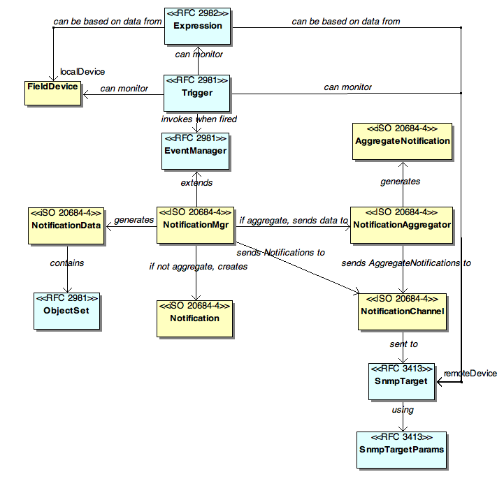
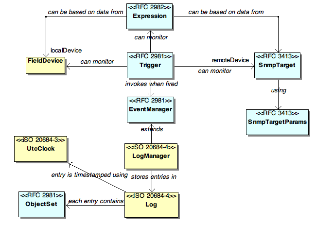
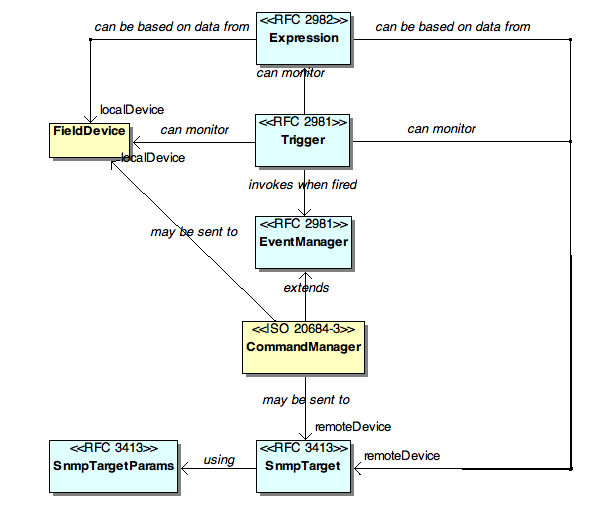
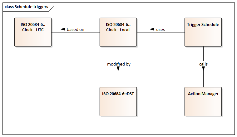
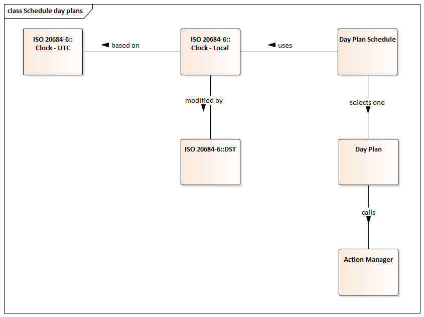
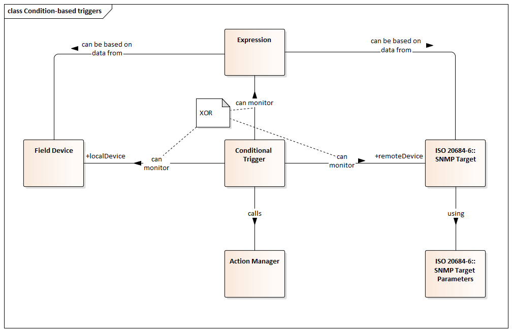
Get in touch
Phasellus convallis elit id ullamcorper pulvinar. Duis aliquam turpis mauris, eu ultricies erat malesuada quis. Aliquam dapibus, lacus eget hendrerit bibendum, urna est aliquam sem, sit amet imperdiet est velit quis lorem.
Should feature-specific parameters of the owner table be editable while the row is active or should changes require disabling the row. Based on unintended consequences of disabling a row along with perhaps a desire to allow some administrators to configure feature-specific details but not deleting an owner, the current draft has assumed that changes can be made while an owner is active.